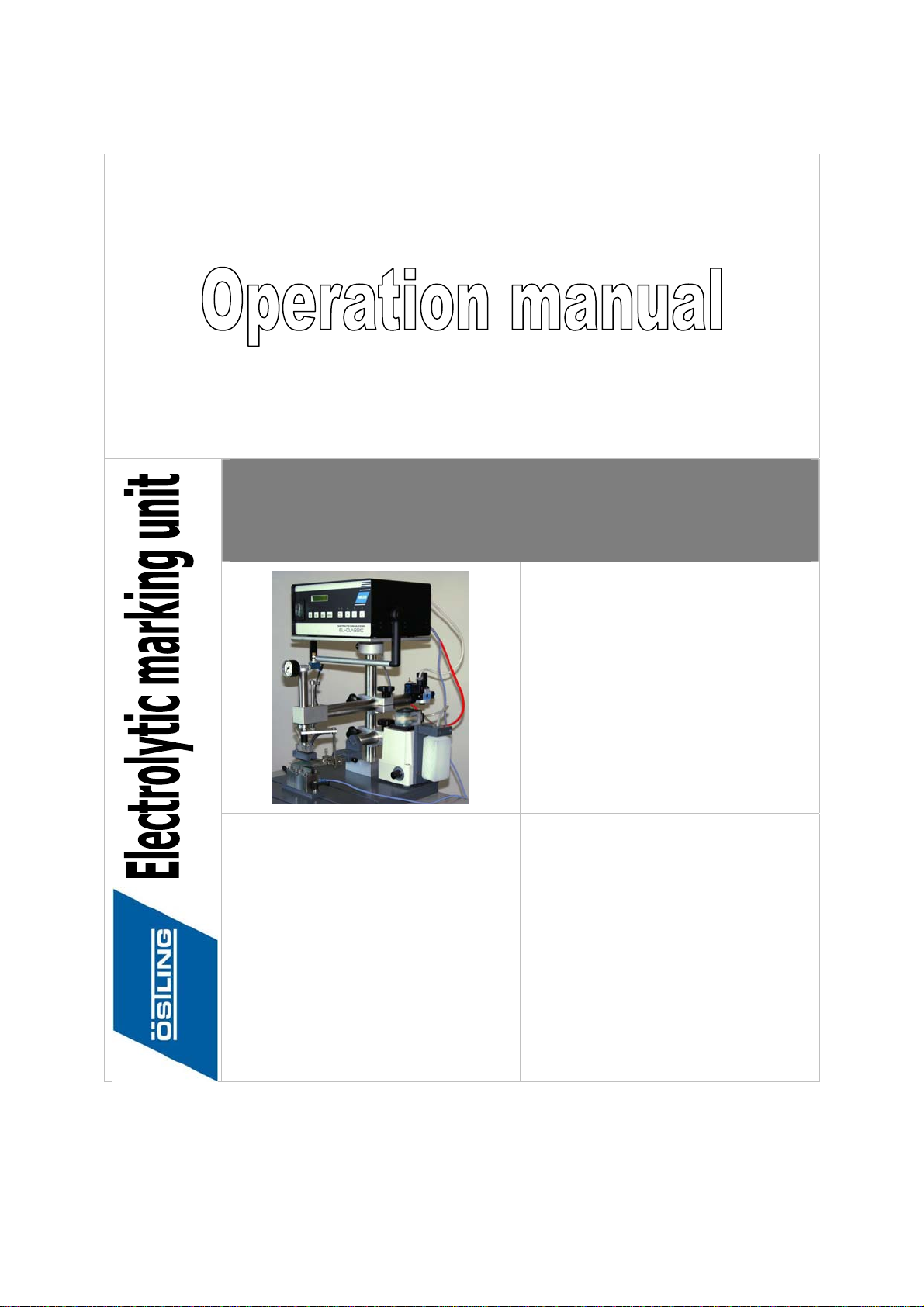
OSTLING EMP/MODULMAT User manual
E
EM
MP
P
/
/
M
MO
OD
DU
UL
LM
MA
AT
T
Ö S T L I N G
Markiersysteme GmbH
Broßhauser Str. 27
42697 Solingen - Deutschland
Tel.: +49 (0) 212 - 26 96 0
Fax.: +49 (0) 212 - 26 96 199
www.ostling.com
Edition: 01/2005

The document was written in the Technical documentation department of the company
ÖSTLING Markiersysteme GmbH.
All rights at this documentation, in particular the right of the duplication and spreading as well
as the translation are at ÖSTLING Markiersysteme GmbH, also for the case of patent right
registrations. No part of the documentation may be reproduced in any form without previous
written agreement of the company ÖSTLING Markiersysteme GmbH or processed, multiplied
or spread using electronic systems. Mistake and technical subject to change.
©
ÖSTLING Markiersysteme GmbH
ÖSTLING Markiersysteme GmbH is not responsible for any errors in this documentation. A
liability for indirect and direct damage, which develops in connection with the supply or the
use of this documentation, is impossible, as far as this is legally permissible.

B_EU_EMP_en.doc
ÖSTLING Markiersysteme GmbH Operation manual EMP 3
Table of contents
1Safety............................................................................................................ 4
1.1 Definitions................................................................................................... 4
1.2 Operational safety...................................................................................... 5
Intended use of the marking equipment.................................................. 5
1.3 Measures taken by the user/operator ........................................................ 6
Consider warning plates and references ................................................ 6
Personnel instruction............................................................................... 6
Duty to care in handling the equipment................................................... 7
Use of intended spare parts and operational funds................................ 7
Water protection...................................................................................... 8
1.4 Measures of the manufacturer................................................................... 9
1.5 Danger overview ........................................................................................ 9
2Product description .................................................................................. 10
2.1 Technical data of the control.................................................................... 10
2.2 Operating devices and components ........................................................ 11
2.3 Accessories.............................................................................................. 14
3Set-up ......................................................................................................... 14
3.1 Set the input voltage ................................................................................ 14
3.2 Setting up the EMP or MODULMAT ........................................................ 16
EMP....................................................................................................... 16
MODULMAT.......................................................................................... 18
3.3 Preparing the marking head..................................................................... 19
4Operation ................................................................................................... 21
4.1 Programming a marking with EU CLASSIC............................................. 22
Default settings...................................................................................... 24
4.2 Programming a marking with EU EXPERT.............................................. 24
Set the adjustments............................................................................... 25
Set the marking options for pulse marking............................................ 29
Working with files .................................................................................. 31
Set the language................................................................................... 32
Query of service data............................................................................ 33
Default settings...................................................................................... 33
4.3 Marking a product .................................................................................... 34
4.4 Choice of electrolytes............................................................................... 35
4.5 Trouble shooting ...................................................................................... 36
Problem: No mark at all......................................................................... 36
Problem: Mark is not clear .................................................................... 36
Problem: Black spots around the mark................................................. 36
Problem: Magnet valve does not operate ............................................. 37
5Maintenance............................................................................................... 37

B_EU_EMP_en.doc
ÖSTLING Markiersysteme GmbH Operation manual EMP 4
1 Safety
With the EMP/MODULMAT you have an electrolytic marking system, which is
on the newest state of the art concerning safety and which is reliable in service.
We confirm to you with the EEC conformity explanation and the CE-indication at
the equipment that the EMP/MODULMAT corresponds to the fundamental
safety and health requirements of the EEC machine guideline 98/37/EG.
The type plate is together with the CE-indication on the back of the equipment.
We as manufacturers of the marking equipment want to make you familiar as
operators by an extensive safety chapter with the safety concept of the
equipment and refer to possible dangers and measures.
Note
Consider the generally accepted safety and rules for the prevention of accidents
going beyond these references.
1.1 Definitions
... is the range in the periphery of the marking equipment, in which safety or the
health of a person is endangered by the stay in this range.
... is the person, in whose working area the marking equipment is set up and
operated.
... are the persons, who are responsible for transport, list, start-up, enterprise,
maintenance including cleaning and repair of the marking equipment.
Danger area
User
Operator/
Personnel

B_EU_EMP_en.doc
ÖSTLING Markiersysteme GmbH Operation manual EMP 5
1.2 Operational safety
The marking equipment is built according to the state of the art and reliable in
service.
From this marking equipment however dangers can proceed, if it is used by not
trained personnel inappropriately or to not intended use. Therefore threatens:
•Dangers for the safety of the operator.
•Impairment of the marking equipment and further real values of the user.
•Impairment of the efficient work of the equipment.
Intended use of the marking equipment
The EMP/MODULMAT is an electrolytic marking system for marking products
with electrically leading surface.
Intended use means in addition:
•The installation of the marking equipment and its operation must stand in
conformity with the valid national regulations of the user country. For their
observance the user is responsible.
Impermissible is:
•Arbitrary changing or changes of the marking equipment by the user or
operator.
•Each function, which could impair safety.
It is possible to interconnect the parts of the equipment so that a short-circuit is
manufactured. This is e.g. the case, if the marking head contacts the baseplate
during the marking or if the positive cable is connected directly with the negative
cable. Such functions are generally inadmissible!
Danger of a short-circuit!
High current flow. Safety device is destroyed.
¾The marking head may not come into contact with the baseplate.
No liability with not intended use!
Each use going beyond that is not considered as intended. For material
damage and personal injuries resulting from this the manufacturer is not
responsible; the risk for this carries alone the user.
B_EU_EMP_en.doc
ÖSTLING Markiersysteme GmbH Operation manual EMP 6
1.3 Measures taken by the user/operator
Consider warning plates and references
With the operation of the marking equipment also actions are to be
implemented, from which dangers can proceed. In this manual the instructions
for implementing such actions warning references are placed in front. At the
equipment are in addition appropriate warning plates.
Note
Mind the warning references!
Mind the commands and interdictions of the warning references. They serve
your protection.
These warning references include:
•A symbol.
•References to the source and kind of the danger.
•Instructions, how you can avoid the danger.
Example:
Electrolytes are oxidizing substances!
Danger of poisoning.
¾Do not swallow the electrolyte and do not bring it on the mucous mem-
branes or eyes.
Personnel instruction
The marking equipment may be served, waited and repaired only by authorized,
trained and instructed personnel.
Work on the electrical and pneumatic equipment may be implemented only by
particularly trained specialists.
In addition the following measures must be accomplished, before the personnel
takes up the work on the equipment:
•Instruct over arising dangers.
•The user must obligate, to the extent necessary, the personnel for carrying
protective clothing and gloves.
•Competencies for operation, maintenance and repair must be clearly
specified, so that under the aspect of safety no unclear authority arises.
•Read the technical documentation of the equipment. It is recommended to
the user to be confirmed in writing in each case that the personnel read and
understood the technical documentation.

B_EU_EMP_en.doc
ÖSTLING Markiersysteme GmbH Operation manual EMP 7
Duty to care in handling the equipment
Guarantee perfect condition of the equipment:
•The user and/or the circle of acquaintances assigned by him may operate
the equipment exclusively in the perfect condition.
•The user must ensure cleanliness and clarity of the work place at the
equipment by appropriate instructions and controls.
•The user must provide for sufficiently admission of fresh air in the work
spaces.
•The operator must announce occurring changes (including the operational
behaviour) at the equipment, which impair safety, immediately to the user.
In addition the equipment must be examined at least once per shift for
outwardly recognizable lack and damage.
With all work, that concern transport, installation, start-up, operation,
maintenance and repair, the prescribed switching off procedures must be kept:
•With all adjusting, maintenance and repairs the equipment must always be
switched off over the MAIN SWITCH. Exceptions of it, with which the
equipment must remain switched on with appropriate work, are noted in the
manual in each case.
•With work on pneumatics:
- Turn off and lock the compressed air supply.
- Wait at least 5 s after turning off the compressed air supply, until the
pressure diminished itself.
- Examine whether the operating pressure dropped on 0 bar. Read off
the current operating pressure from the appropriate manometer.
Use of intended spare parts and operational funds
Original parts and accessories are particularly conceived for the marking
equipment. Spare parts for original parts and accessories, which are not
supplied by the manufacturer of the marking equipment, are not examined and
approved of the manufacturer. The installation and/or the use of such products
can change therefore perhaps constructionally given characteristics of the
marking equipment and endanger safety.
Note
For damage, which results from the use of non-original parts and accessories
and/or not adequate installation or exchange of original parts and accessories,
each liability of the manufacturer is impossible.

B_EU_EMP_en.doc
ÖSTLING Markiersysteme GmbH Operation manual EMP 8
When using the intended operational funds the instructions for use must be
kept. As far as a safety data sheet (European guideline 91/155/EWG) of the
manufacturer for operational funds is prescribed, the references made there
must be considered obligatorily, like e. g.:
•Chemical characterization.
•Physical and safety-relevant data.
•Transport.
•Regulations.
•Safety measures, Storage and Handling.
•Measures to be taken in case of fire and accidents.
•Toxicological information.
•Ecological information.
This applies in particular to the adequate disposal of operational funds. For this
the safety data sheet indicates the prescribed kind of disposal and the waste
key. The safety data sheet can be requested with the manufacturer of the
operational funds.
Water protection
In the Federal Republic of Germany the concern principle applies to devices
with water-endangering materials. This means that by handling these materials
no impurities of waters may arise. This is the central statement § 19 of the water
conservation law (WHG). In plant regulations (VAwS) and administrative
regulations (VVAwS) of the states of the Federal Republic one concretizes, as
is to be followed this concern principle.
Substance hazardous to waters Electrolyte
Water pollution class WGK 1
Volume of the substances hazardous to
waters ≤100 l
Endangerment stage overall A
Water protection information Tab. 1

B_EU_EMP_en.doc
ÖSTLING Markiersysteme GmbH Operation manual EMP 9
1.4 Measures of the manufacturer
The marking equipment contains a transformer, which reduces the input voltage
(AC) to max. 24V output voltage alternating current (AC) or direct current (DC).
With intended use of the equipment therefore no voltage dangerous for humans
is delivered by the equipment.
Due to the building method of the hand marking equipment it is possible to
affect live parts during the marking. Due to the low voltage of max. 24V this is
harmless.
For persons with cardiac pacemaker also a voltage of max. 24V can become
lethal, since the cardiac pacemaker is impaired in its function. For this reason
the work with the marking equipment is forbidden for persons with cardiac
pacemakers.
Danger of life for persons with cardiac pacemaker!
¾Work with the marking equipment is forbidden for persons with cardiac
pacemaker.
The electrolytes used depending upon marking type are oxidizing substances.
In the case of their use the instructions for use must be kept (see page 8).
1.5 Danger overview
The following danger overview points out the substantial potential endanger-
ments of lives and health by the equipment. By conceiving and design as well
as the safety devices of the equipment according to the EEC machine guideline
98/37/EG an endangerment of the personnel is excluded. If the user of the
equipment can seize additional measures for the reduction of possible
remainder dangers, this is to be taken from the danger overview.
Type of endangerment Spot of endangerment Danger Additional measure
Mechanical endangerment
•By squeezing
•Contact pin
Risk of injury
-
Electrical endangerment
•By electrical contact
•Contact with parts that
are under voltage
during the marking
Danger of life for persons
with cardiac pacemaker
Persons with cardiac
pacemaker are not allowed
to work with the equipment.
Endangerment caused by
substances
•By contact along or
inhalation of poisonous
liquids, gases, nebulas,
steams and types of
dust
•Electrolyte
Risk of health
Do not swallow the electro-
lyte and do not bring it on
the mucous membranes or
eyes.
Wash hands before pausing
and after work.
Tab. 2
Cardiac
pacemaker

B_EU_EMP_en.doc
ÖSTLING Markiersysteme GmbH Operation manual EMP 10
2 Product description
The EMP or MODULMAT is a semiautomatic marking system, with which the
products are marked from above. The product to be marked lies on an
adjustment block, during the marking the marking head is pressed pneumati-
cally on the product to be marked. The marking takes place on the upper
surface of the product.
Products with electrically leading surface can be marked. The marking takes
place via a current pulse, which is led by the coinage of the stencil. Thus an
accurate image develops on the product to be marked. The surface form of the
product to be marked is arbitrary.
The EMP/MODULMAT consists of the following building groups:
•Marking control EU CLASSIC 300, EU CLASSIC 500, EU EXPERT 300 or
EU EXPERT 500.
•Mechanics (electrolyte basin and -storage vessel, stand, product admis-
sion).
•Pneumatics.
•Electrolyte pump.
The input voltage of the marking control amounts to 115 V or 230 V alternating
current (AC), the output voltage can be adjusted steplessly from 0 to 24 V
alternating current (AC) or direct current (DC). Power output amounts to 310 VA
or 510 VA.
2.1 Technical data of the control
EU CLASSIC 300
EU EXPERT 300 EU CLASSIC 500
EU EXPERT 500
Input voltage [V] 115 or 230, AC
(see type plate) 115 or 230, AC
(see type plate)
Output voltage [V] 0 - 24, AC or DC 0 - 24, AC or DC
Power [VA] 310 510
Dimensions Height [mm] 140 140
Width [mm] 380 380
Depth [mm] 220 220
EMV checked EN 50081-1, EN 50082-1
Tab. 3
B_EU_EMP_en.doc
ÖSTLING Markiersysteme GmbH Operation manual EMP 11
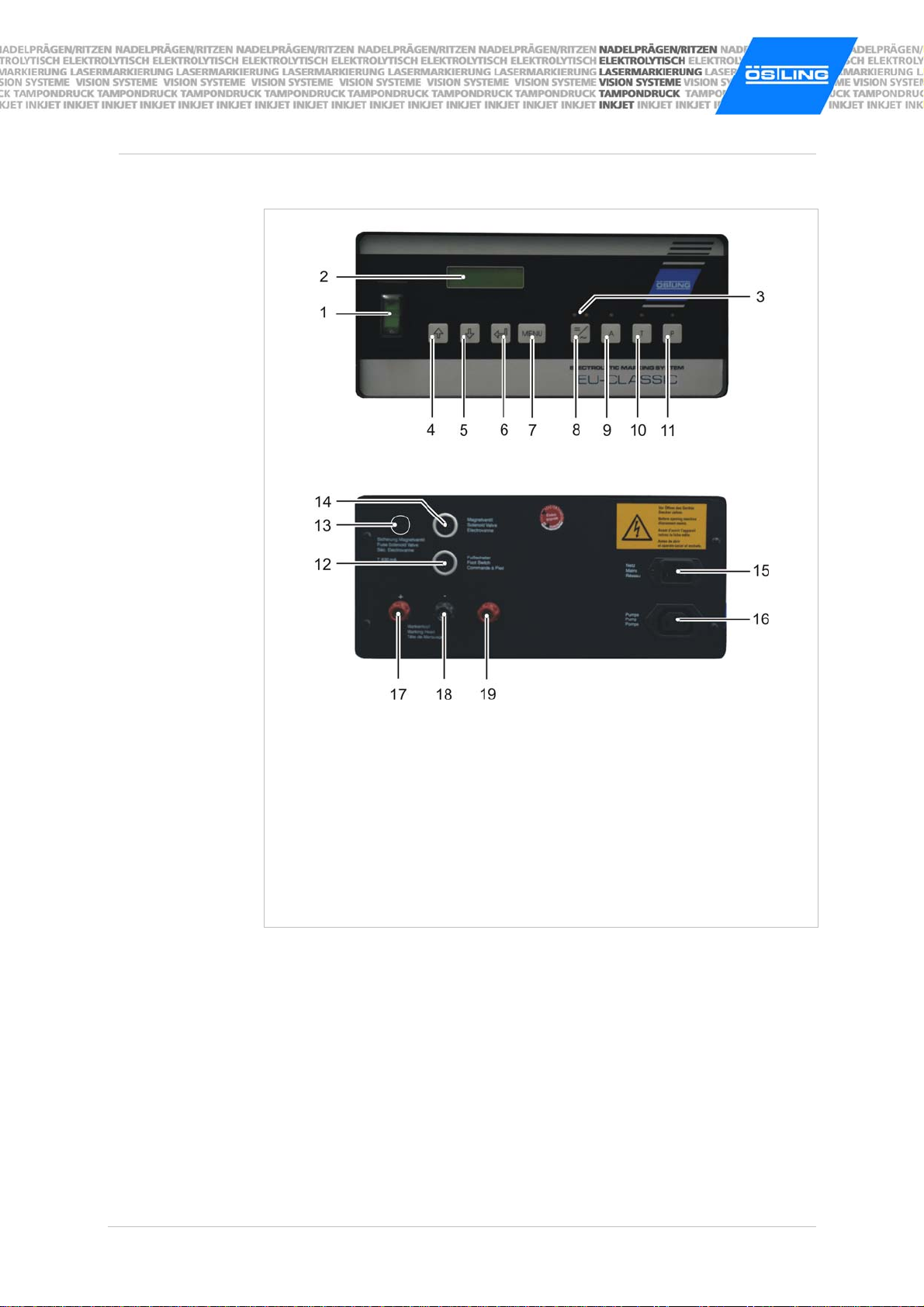
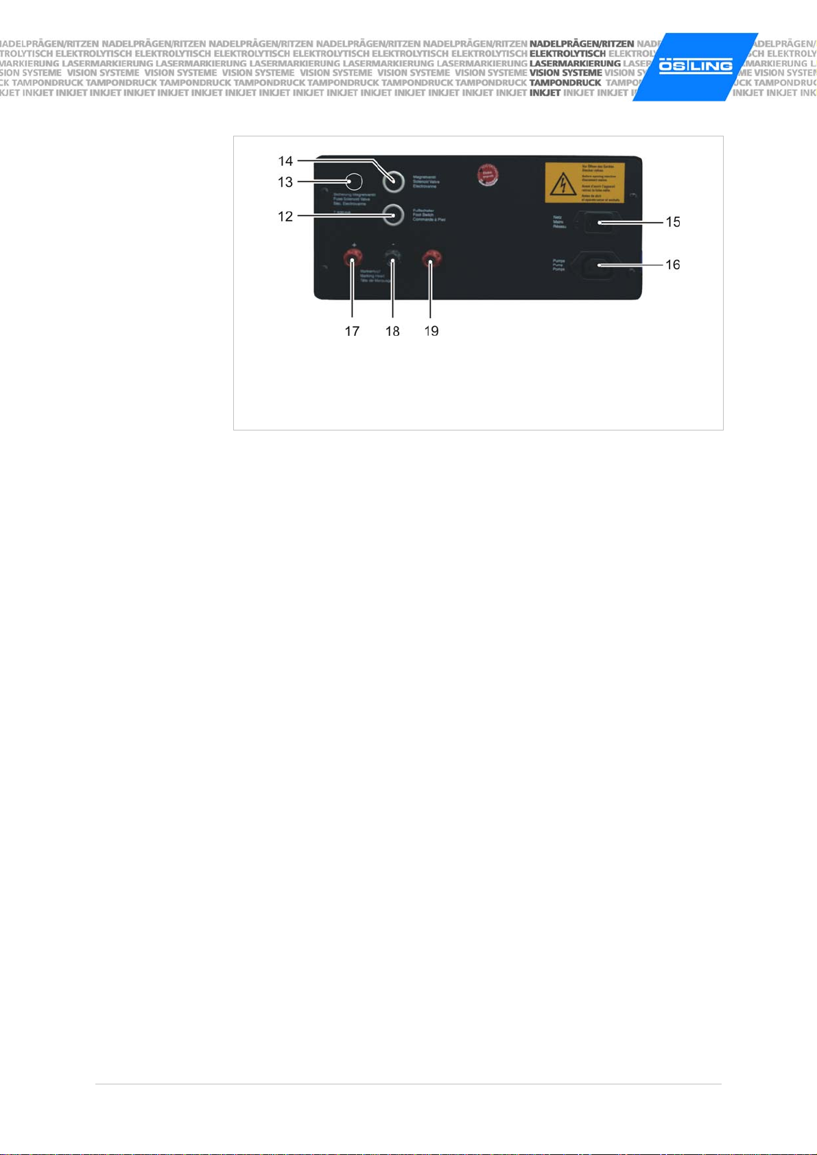
2.2 Operating devices and components
1 MAIN SWITCH
2 Display
3 LEDs AC and DC
4 Pushbutton ↑(increase values)
5 Pushbutton ↓(decrease values)
6 ENTER
7 MENU
8 Pushbutton AC/DC
9 AUTOMATIC
10 TIMER
11 PUMP
12 Connection foot switch
13 Fuse magnet valve
14 Output magnet valve
15 Connection line cord
16 Connection pump
17 Connection positive cable
18 Connection negative cable
19 Hard metal output (option)
Operating devices EU CLASSIC / EU EXPERT Fig. 10009
The grasp handle (not illustrated) serves for carrying and inclining/slanting the
equipment. With pressure on the two lateral pushbuttons the grasp handle can
be adjusted in 30°-steps.
B_EU_EMP_en.doc
ÖSTLING Markiersysteme GmbH Operation manual EMP 12
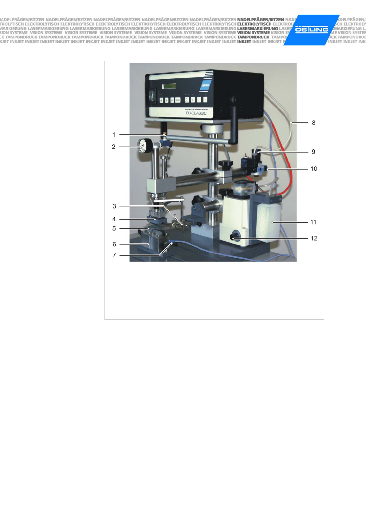
1 Throttle cylinder speed
2 Pressure gauge
3 Stencil holder X-Y-Z
4 Marking head
5 Stencil glued on stencil cover
6 Adjustment block
7 Connection negative cable
8 Cable and plug magnet valve
9 Pressure reducing valve
10 Compressed air connection
11 Electrolyte storage vessel
12 Electrolyte fine dosage
Components EMP Fig. 10102
B_EU_EMP_en.doc
ÖSTLING Markiersysteme GmbH Operation manual EMP 13
With MODULMAT, which is the compact design, control and mechanics are
integrated into a plastic housing. Most connections are already factory-installed
cabled. The connections at the back of the control are not accessible. The
connections, which you as a customer must reach, are shifted on the back of
the plastic housing:
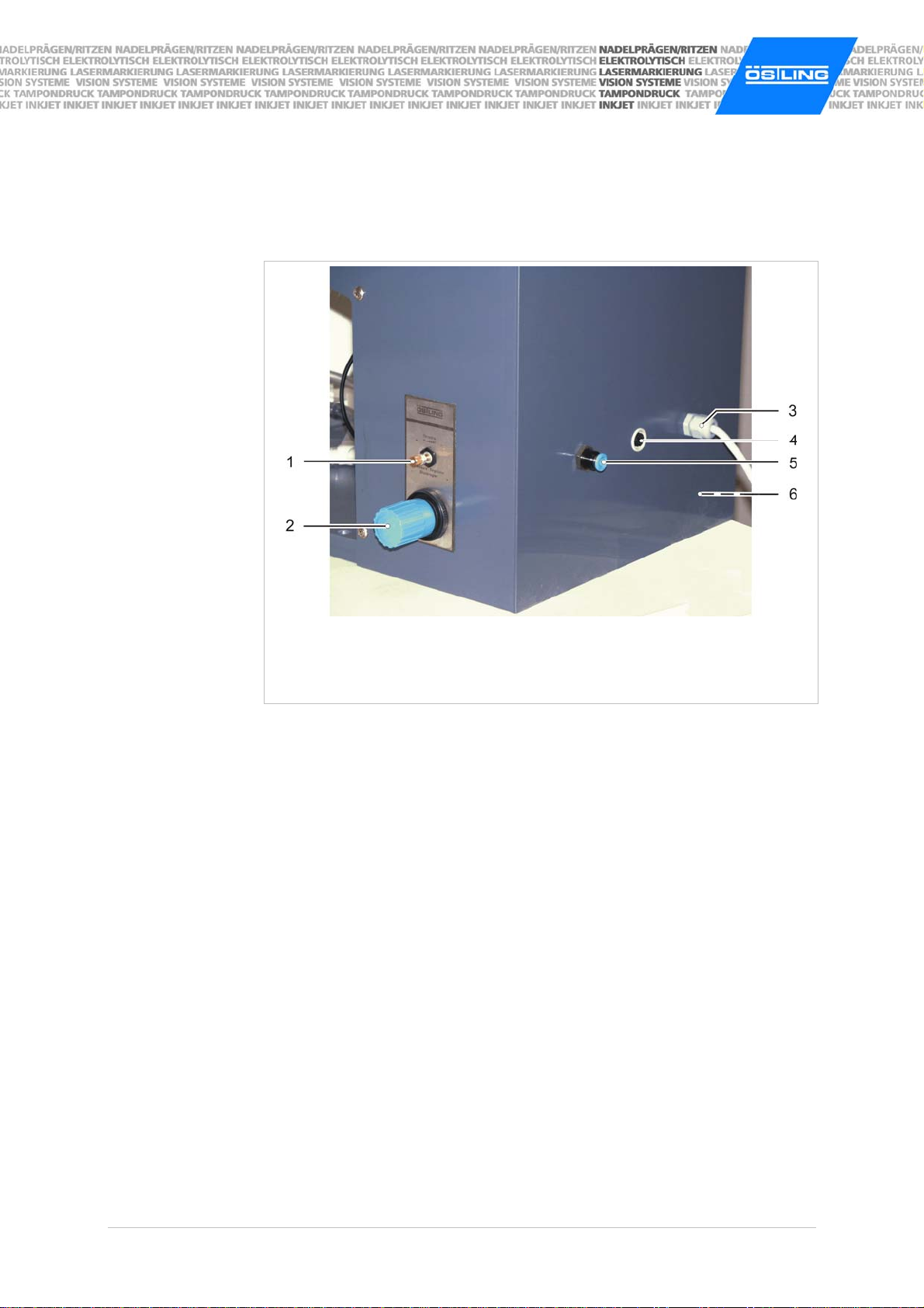
1 Throttle for cylinder speed
2 Pressure reducing valve
3 Line cord
4 Connection foot switch
5 Compressed air connection
6 Connection pump (at the side)
Deviant components MODULMAT Fig. 10123
Note
Depending upon ordered design the appearance of the EMP/MODULMAT can
deviate slightly from these illustrations.

B_EU_EMP_en.doc
ÖSTLING Markiersysteme GmbH Operation manual EMP 14
2.3 Accessories
The equipment can be supplied with an optional hard metal output. 10 V, AC
are impressed permanently on the hard metal output. This tension cannot be
adjusted.
A hard metal output is suitable for marking hardened materials e. g. tools. With
the use of the hard metal output better results can be obtained on such
materials as with the use of the standard connections.
Except an ÖSTLING long-term stencil also short-time stencils can be used
In order to make your own short-time stencils for frequently changing texts very
fast and flexibly, the following accessories are available:
•Stencil production system ÖSTLING PT (different versions).
•9-pin printer with Software Stencil Creator.
For further technical support please contact our technicians. They answer gladly
your questions about different marking heads and further accessories like e. g.
customized devices or installation of the equipment into your production line.
3 Set-up
3.1 Set the input voltage
The preset input voltage (115 V or 230 V) can be set finely for adjustment to
other electricity mains. The following input voltages are available:
•110 V.
•120 V.
•220 V.
•230 V.
•240 V.
The marking equipment must be opened for fine adjustment of the input
voltage!
Danger of electric shock.
¾Only an electrician is allowed to adjust the input voltage.
¾Before opening the equipment pull the line cord.
Hard metal
output
Types of stencils

B_EU_EMP_en.doc
ÖSTLING Markiersysteme GmbH Operation manual EMP 15
1. Loosen the 3 upper screws on both sides of the equipment.
2. Take off the cover of the equipment.
Transformer appears:
1 Fuse magnet valve
2 Sticker technical data 3 Preset input voltage (here: 230 V)
Transformer Fig. 10014
3. Set the desired input voltage with the jumpers as shown on the sticker (2).
The net frequency (50 or 60 Hz) is automatically detected by the equipment.
Note
The 24V, DC output (output magnet valve) is secured with a second fuse (1)
additionally to the magnet valve fuse on the back of the equipment. This fuse
prevents the destruction of the internal jumper rectifier with a overcurrent
(>1 A), which can be caused e.g. by a short-circuit. The rated current intensity
of the fuse stands on the sticker (2).

B_EU_EMP_en.doc
ÖSTLING Markiersysteme GmbH Operation manual EMP 16
3.2 Setting up the EMP or MODULMAT
EMP
Note
The connections for the cables on the back of the equipment are equipped with
an isolating head. Both cables with plug can be tucked in and cables with
suitable lugs can be tightened.
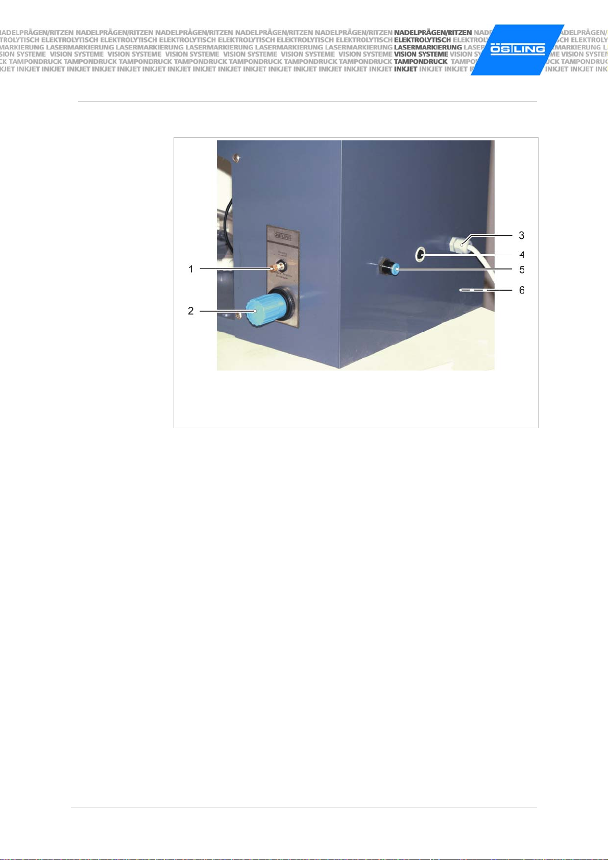
1 Throttle cylinder speed
2 Pressure gauge
3 Stencil holder X-Y-Z
4 Marking head
5 Stencil glued on stencil cover
6 Adjustment block
7 Connection negative cable
8 Cable and plug magnet valve
9 Pressure reducing valve
10 Compressed air connection
11 Electrolyte storage vessel
Connections EMP Fig. 10124
B_EU_EMP_en.doc
ÖSTLING Markiersysteme GmbH Operation manual EMP 17
12 Connection foot switch
13 Fuse magnet valve
14 Output magnet valve
15 Connection line cord
16 Connection pump
17 Connection positive cable
18 Connection negative cable
19 Hard metal output (option)
Connections EU CLASSIC / EU EXPERT Fig. 10005
1. Plug in the line cord (15).
2. Tuck the plug of the electrolyte pump into the connection pump (16).
3. Plug in the foot switch (12).
4. Tuck the plug magnet valve (8) into output magnet valve (14).
5. Tuck the plug of the red positive cable into the red connection (17) at the
control.
6. Connect the connection negative cable (7) at the adjustment block via blue
negative cable with the black connection (18) at the control.
7. To supply the EMP with compressed air: Lead tube PUN 8 from the internal
compressed air supply to the compressed air connection (10) of the EMP.
The pressure must amount to 4.5 to 5 bar. With the pressure reducing valve
(9) the pressure can be set finely.
8. Fill electrolyte into the electrolyte storage vessel (11, max. 250 ml).
B_EU_EMP_en.doc
ÖSTLING Markiersysteme GmbH Operation manual EMP 18
MODULMAT
1 Throttle for cylinder speed
2 Pressure reducing valve
3 Line cord
4 Connection foot switch
5 Compressed air connection
6 Connection pump (at the side)
Connections MODULMAT Fig. 10123
1. Plug in the line cord (3).
2. Tuck the plug of the electrolyte pump into the connection pump (6).
3. Plug in the foot switch (4).
4. To supply the MODULMAT with compressed air: Lead tube PUN 8 from the
internal compressed air supply to the compressed air connection (5) of the
MODULMAT.
The pressure must amount to 4.5 to 5 bar. With the pressure reducing valve
(2) the pressure can be set finely.
5. Fill electrolyte into the electrolyte storage vessel (max. 250 ml).

B_EU_EMP_en.doc
ÖSTLING Markiersysteme GmbH Operation manual EMP 19
3.3 Preparing the marking head
A black/white marking is possible on most of the metals, see page 35.
1 Marking head
2 Cartridge
3 Black felt
4 Conductive net
5 Stencil glued on stencil cover
Marking head for black/white markings Fig. 10103
1. Tailor black felt (3) to the size of the surface of the marking head (2).
2. Tailor conductive net (4) so that it gets over approx. 15 mm at all sides of
the marking head.
3. Place the felt onto the marking head.
4. Lay the conductive net over the felt.
5. Clamp the felt and conductive net with the cartridge (3).
6. Attach the marking head to the EMP/MODULMAT (4, Fig. 10102, page 12).
7. Attach the stencil glued on stencil (5) to the stencil holder (3, Fig. 10102,
page 12).
Black/white
marking

B_EU_EMP_en.doc
ÖSTLING Markiersysteme GmbH Operation manual EMP 20
A deep marking is possible on many metals, but a general statement cannot be
made. see page 35.
1 Marking head
2 O-ring seal 3 Green felt
5 Stencil glued on stencil cover
Marking head for deep markings Fig. 10104
Note
You don't need conductive net for deep marking.
1. Tailor green felt (3) so that it gets over approx. 15 mm at all sides of the
marking head (1).
2. Place the felt onto the marking head.
3. Bend the O-ring seal (2) over the felt.
4. Attach the marking head to the EMP/MODULMAT (4, Fig. 10102, page 12).
5. Attach the stencil glued on stencil (5) to the stencil holder (3, Fig. 10102,
page 12).
Deep marking
Table of contents


