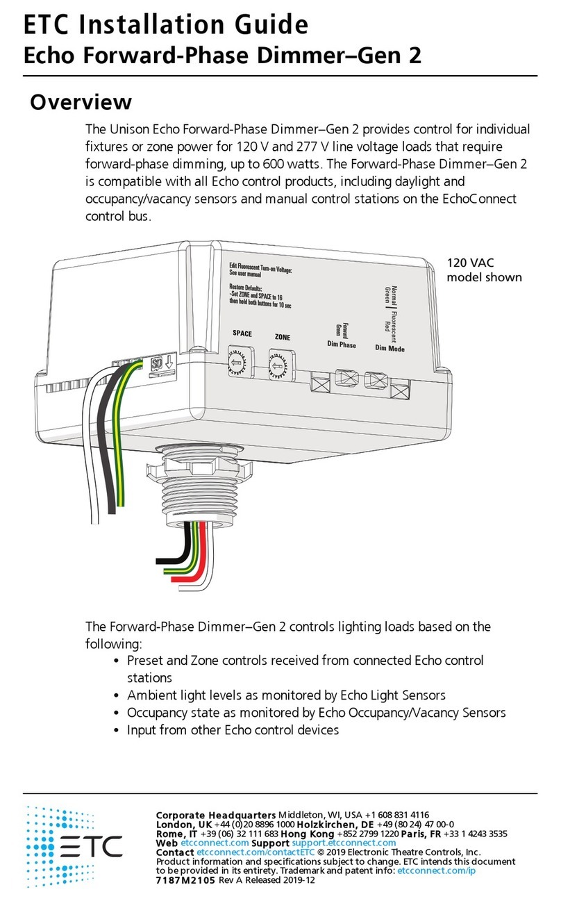
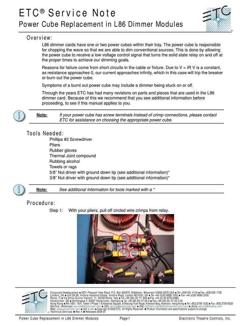
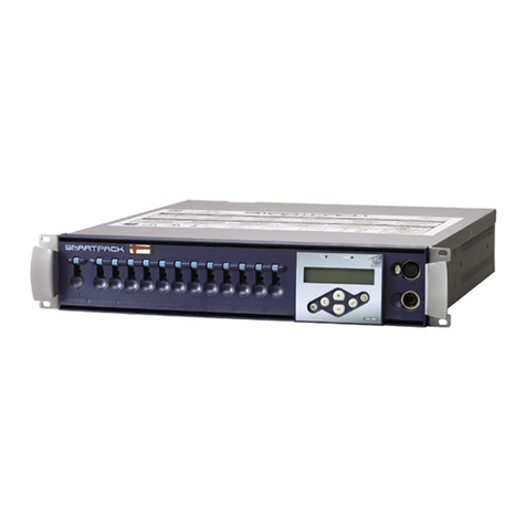
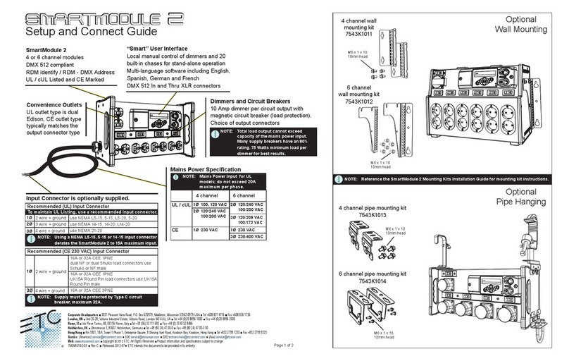
ETC SMARTRACK User manual

smartrack
USER MANUAL
Electronic Theatre Controls Ltd.
5 Victoria Industrial Estate, Victoria Road
London W3 6UU, England
(+44) 181 896 1000 FAX (+44) 181 896 2000
Copyright 1995 Electronic Theatre Controls Ltd.
Specifications subject to change. Revised 8/95
2000M1001

smartrack
User Manual
page i
Introduction – Please read this first
Thank you for choosing ETC Smartrack digital dimmers. We are
sure that you will be pleased with Smartrack, and wish you a
long and happy association with our company and its products.
We at ETC have done everything we can to ensure that your
new dimming system will function perfectly, will be easy to
install, and will give you many years of reliable service.
This manual contains detailed instructions for installing, using
and maintaining ETC Smartrack dimmers. Please follow them
carefully, to guarantee best results. Neither ETC Ltd nor its
distributors can accept any liability whatsoever arising from the
guidelines in this manual not being followed.

Table of contents
1. Digital dimming explained ...................................................1
2. About Smartrack..................................................................2
2.1 Mechanical............................................................................2
2.2 Electrical................................................................................4
2.3 Filtering.................................................................................4
2.3.1 Standard risetime choke ..........................................................4
2.3.2 High risetime choke ................................................................5
2.4 Rack control...........................................................................5
2.4.1 Dimmer profile .......................................................................5
2.4.2 Response speed......................................................................5
2.4.3 Dimmer test............................................................................6
2.4.4 Reference voltage ...................................................................6
2.5 Thermal management..............................................................6
3. Getting Started – What’s in the box......................................8
3.1. Smartrack ..............................................................................8
3.1.1 Rack .....................................................................................8
3.1.2 Power assemblies ...................................................................9
4. Installation.........................................................................10
4.1. Environmental considerations .................................................10
4.2. Planning and marking out......................................................10
4.2.1 Marking out a wall ...............................................................11
4.2.2 Planning an island installation ................................................12
4.3. Wall fixings .........................................................................12
4.4. Assembly and mounting.........................................................12
4.5. Power wiring........................................................................14
4.5.1 Standard Smartrack ..............................................................16
4.5.2 Connecting single and bi-phase systems ..................................17
4.5.3 Connecting Delta systems ......................................................17
page ii
Smartrack User Manual ETC Ltd

4.5.4 Cascading a stack of Smartracks ...........................................17
4.6. Load wiring..........................................................................19
4.6.1 Installing load wires ..............................................................19
4.7. Identifying and testing power and load wiring..........................19
4.8. Signal wiring .......................................................................20
4.9. Power assemblies .................................................................21
4.9.1 Installation ...........................................................................21
4.9.2 Connecting load wiring.........................................................21
4.9.3 Connecting power wiring – RCD option fitted...........................23
4.9.4 Connecting power wiring – without RCD option .......................25
4.9.5 The power assembly signal looms...........................................25
4.10 Smartrack door ....................................................................27
4.10.1 Mounting the door ................................................................27
4.10.2 Connecting earth and power wiring........................................27
4.10.3 Smartrack CPU jumper settings...............................................27
4.10.4 Connecting power assembly signal looms................................28
4.10.5 Connecting DMX input/output wiring......................................29
4.10.6 Fitting blanking plates ...........................................................29
4.10.7 Closing the door...................................................................29
4.10.8 Fitting dimmer number strips ..................................................30
5. Commissioning and configuration.......................................31
5.1. Switching on........................................................................31
5.2. Power and signal indicators...................................................31
5.3. Modular Smartrack dimmer level indicators..............................32
5.4. Battery supported memory .....................................................33
5.5. Using offline mode................................................................33
5.5.1 Verifying rms line voltage in offline mode ................................34
5.5.2 Setting the output voltage range in offline mode .......................34
5.6. Testing dimmer circuits with the rotary potentiometer.................35
5.7. DMX control.........................................................................35
5.7.1 Terminating the DMX line.......................................................36
page iii
Smartrack User ManualVersion 1.2

5.7.2 Good/bad data ...................................................................36
5.7.3 Setting the rack address ........................................................36
5.7.4 Large installations .................................................................37
5.7.5 Testing dimmers with DMX.....................................................37
5.8. Dimmer profiles ....................................................................37
5.8.1 What is a profile?.................................................................37
5.8.2 Smartrack standard profiles ...................................................38
5.8.3 Dimmer and console set profiles .............................................39
5.8.4 Setting profiles .....................................................................39
5.9. Response speed....................................................................40
5.9.1 Setting response speed..........................................................41
5.10 Important note – Exiting from user interface mode.....................41
6. Smartrack operational summary........................................42
6.1. Accessing the control panel....................................................42
6.2. Address setting.....................................................................43
6.3. Dimmer mode ......................................................................43
6.3.1 Testing dimmers at levels .......................................................43
6.3.2 Profile mode.........................................................................44
6.3.3 Speed mode ........................................................................44
6.4. Offline mode........................................................................45
6.4.1 Checking line voltage............................................................46
6.4.2 Setting the output voltage scale ..............................................46
6.4.3 Clearing configuration settings ...............................................46
7. Routine maintenance..........................................................47
7.1. Torque settings .....................................................................47 ...
7.2. Cleaning .............................................................................47
7.3. Inspecting dimmer module connectors .....................................48
7.4. Control fuse ratings...............................................................48
7.5. Battery replacement ..............................................................48
page iv
Smartrack User Manual ETC Ltd

8. Technical support ...............................................................49
8.1. Who to call..........................................................................49
8.2. What to tell them ..................................................................49
9. Accessories and options .....................................................50
9.1 RCD protection.....................................................................50
9.2 Single phase adapter kit........................................................50
9.3 Spare numbering sheets ........................................................51
9.4 Load terminal extender kits.....................................................51
10. Spare parts ........................................................................52
page v
Smartrack User ManualVersion 1.2

Notes:
page vi
Smartrack User Manual ETC Ltd

smartrack
USER MANUAL
1. Digital dimming explained
There are good reasons why users of professional dimming equipment are now only
willing to accept true digital dimming equipment, such as ETC Smartrack and
Smartpack. They are:
●Accuracy – digital dimmers are able to regulate output levels to reproduce precisely
recorded intensities, even when mains power is fluctuating.
●Reliability – with fewer electronic components, digital dimmers literally have less
things to go wrong.
●Smarts – with processing power on board, digital dimmers can perform tasks previ-
ously impossible with analogue techniques. These include diagnostic functions, indi-
vidual dimmer profile and response speed settings, and more.
●Cost – a well designed digital dimmer typically uses fewer electronic components
and is therefore cheaper to manufacture.
The key to the accuracy of digital dimmers is regulation. This means that the dimmer is
constantly measuring the rms voltage of each supply phase (a total of 12,800 times per
second in the case of ETC Smartrack) to build up an accurate picture of the condition of
the mains supply to each dimmer. Using this information, the power devices are pre-
cisely controlled, to compensate for any mains voltage fluctuations and produce a con-
stant voltage output for any given control level.
Of course, in an age where virtually all lighting control consoles output the same inter-
nationally accepted digital control signal (USITT DMX512), another plus with digital
dimmers is that no expensive demultiplexer stage is required. The digital signals from
the lighting console are simply connected directly to the dimmers.
page 1

2. About Smartrack
Smartrack is a revolutionary concept in professional digital dimming equipment, offer-
ing a very wide range of system options in an extremely compact package, with many
significant advantages over its competitors:
●Compact size
●Competitive price
●Easy and economical installation
●Highly flexible configuration options
●Basic or modular variants
●All-digital – high reliability, high accuracy
Smartrack is unique in that it offers competitive system solutions at all levels of the market,
and versions exist to cover all requirements, right up to top level broadcast applications.
2.1 Mechanical
Each Smartrack is a proprietary wall mounting steel cabinet, measuring 85cm
wide, 65cm high and 30cm deep, designed to house up to three power assem-
blies (supplied separately), each of which comprises 30kW of dimming, as either
12 x 2.5kW, 6 x 5kW or 3 x 10kW. A hinged steel front door supports all the
system electronics, and the rack is available in two versions, to accept either
basic (hard-wired) or plug-in modular power assemblies.
Smartrack is primarily intended for wall-mounting, and may be installed up to
three high, side by side, or back to back. Smartrack may also be fitted into flight-
cases with custom rear connector panels, for highly cost-effective mobile dimming
systems.
All power, load and signal cables may enter from top, bottom, or through rear
panels and sufficient space is provided for through wiring in a stack of three
Smartracks. Front access only is required for installation and maintenance, and
all terminal screwheads face forward, for easy re-tensioning in service.
page 2
Smartrack User Manual ETC Ltd

Power Assemblies are available either with plug-in modules containing power
devices and LED level indicators, or with power devices mounted on a perma-
nent heatsink. Power assemblies of different ratings may be mixed in a rack, but
basic and modular power assemblies may not be mounted in the same rack.
All controls for rack configuration are mounted on the front panel, and the start
address of the rack is normally displayed, along with power, DMX and thermal
status indicators.
page 3
Smartrack User ManualVersion 1.2
DIGITAL
SmartRack
2.5 2.5 2.5
2.5 2.5 2.5
2.5 2.5 2.5
0205 490 850
0
84
290
496
650
mcb centre
mcb centre
mcb centre
Front view of a modular
Smartrack, showing key
dimensions.
Note that Smartrack is
300mm deep, plus 30mm
for dimmer module handles
on the modular version only.
smartrack
215 630 990
Table of contents
Other ETC Dimmer manuals
