ETC F-Drive FD-RPS-48-1000 User manual

ETC Installation Guide
F-Drive Power Supply
Corporate Headquarters nMiddleton, WI, USA|+1 608 831 4116
Global Offices nLondon, UK|Rome, IT|Holzkirchen, DE|Paris, FR|Hong Kong|Dubai, UAE|Singapore
New York, NY|Orlando, FL|Los Angeles, CA|Austin, TX|©2023 Electronic Theatre Controls, Inc.
Web etcconnect.com |Support support.etcconnect.com |Contact etcconnect.com/contactETC
Trademark and patent info: etcconnect.com/ip |Third-party license agreement info:etcconnect.com/licenses
Product information and specifications subject to change.ETCintends this document to be provided in its entirety.
7148M2140RevAReleased 2023-06
Introduction
Congratulations on your purchase of the ETC F-Drive Power Supply. The F-Drive Power Supply
houses a single power supply and is compatible with an F-Drive R12 LEDdriver.
F-Drive System Design Tool
Visit the F-Drive System Design Tool (etcconnect.com/FDriveSysDesignTool) to design an F-Drive
R12 system with different luminaires, breakout boxes, cable lengths, and other system
components.
Compatible Products
F-Drive Power Supply is compatible with the F-Drive R12 enclosure with up to 12 output cards.
Documentation for Compatible Products
The following documents are available at etcconnect.com/Products/Power-Controls/LED-Drivers/F-
Drive/Documentation.aspx:
•
F-Drive Power Supply Datasheet
•
F-Drive R12 Datasheet
•
F-Drive Series R12 Installation Manual
•
F-Drive R12 and W1 Wiring Reference Guide
Safety
The F-Drive Power Supply is intended for professional use only. Read the entire manual before
using this equipment.
This equipment is not suitable for use in locations where children are likely to be present.
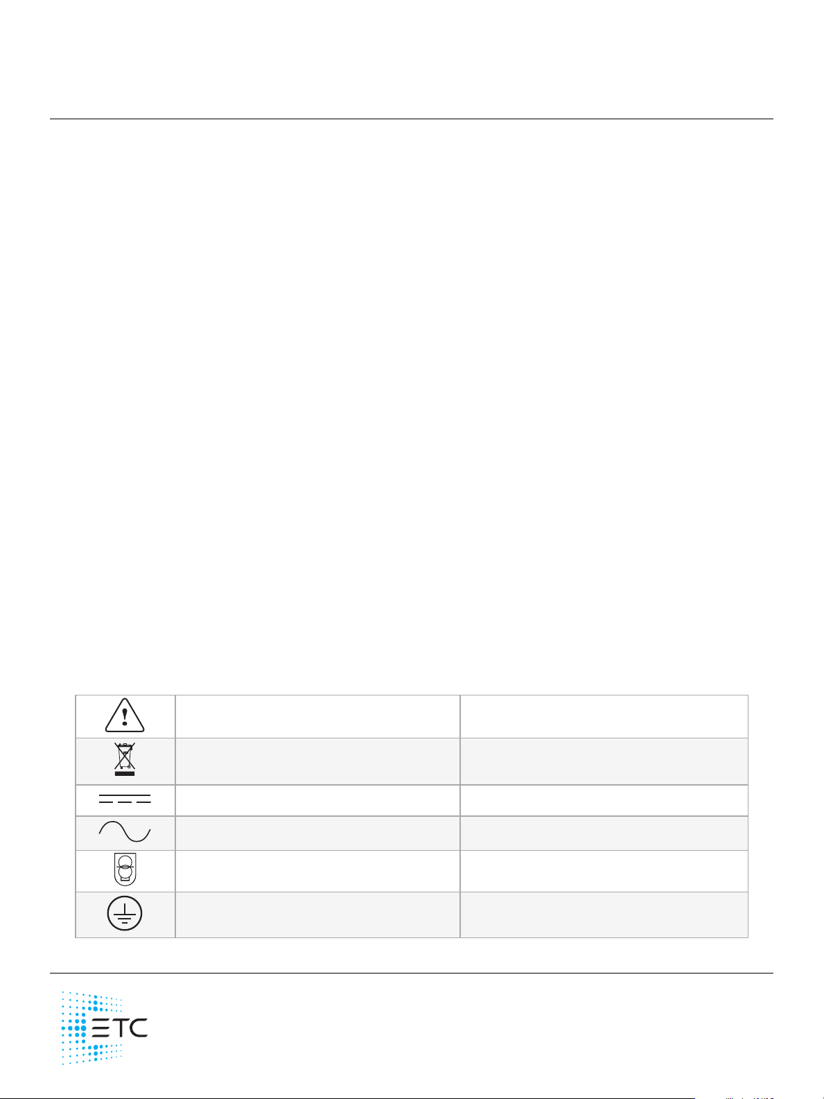
Label Symbols
Power Supply Drivers are conveniently labeled with relevant symbols for your safety. Refer to the
product label to see which symbols apply to your product.
General warning Avertissement général
This product should not be discarded as unsorted
waste but must be sent to separate collection facilities
for recovery and recycling.
Ce produit ne doit pas être jeté avec les déchets
ménagers mais doit être déposé dans une collecte de
déchets électroniques ou dans un point de collecte.
The product input or output is suitable for direct
current only.
L’entrée et la sortie de ce produit convient uniquement
au courant continu.
The product input or output is suitable for alternating
current only.
L’entrée et la sortie de ce produit convient uniquement
au courant alternatif.
Safety extra low voltage device Dispositif de sécurité à très basse tension
Protective earth (ground) Protection Classe I Mise à la terre

ETC Installation Guide
F-Drive Power Supply
F-Drive Power Supply Page 2 of 7 ETC
IMPORTANTSAFEGUARDS
When using electrical equipment, basic safety precautions should always be followed
including the following:
READ AND FOLLOW ALL SAFETY
INSTRUCTIONS.
• Do not use outdoors.
• Do not let power supply cords touch hot surfaces.
• Do not mount near gas or electric heaters.
• Equipment should be mounted in locations and at heights where it will not
readily be subjected to tampering by unauthorized personnel.
• The use of accessory equipment not recommended by the manufacturer may
cause an unsafe condition.
• Do not use this equipment for other than intended use.
• To reduce the risk of fire and overheating, make sure all connections are tight.
• Turn off electrical power before modifying the lighting system in any way.
SAVE THESE INSTRUCTIONS

ETC Installation Guide
F-Drive Power Supply
F-Drive Power Supply Page 3 of 7 ETC
Overview
F-Drive Power Supply
Features
• Compact size:fits19-inch rack, 1U height, 33.1cm (13-1/2 in)depth (not including front
handles)
• Front-panel LEDpower indicator
• Rear On/Off switch
• 100–240VAC input. See
Electrical Specifications on page5
for power ratings.
• Multiple power supply cord options:
‐14/3 NEMA 5-15P to Locking C19 IEC connector (Model FD-RPS-IC-E15)
‐12/3 NEMA 5-20P to Locking C19 IEC Connector (Model FD-RPS-IC-E20)
‐14/3 (2.5mm2) Euro Schuko Plug to Locking C19 IEC Connector (Model FD-RPS-IC-S16)
‐14/3 (2.5 mm2) Euro Ceeform Plug to Locking C19 IEC Connector (Model FD-RPS-IC-C16)
‐14/3 (2.5 mm2)Bare Ends (Euro coloring)to Locking C19 IECconnector
(Model FDR-PS-IC-EUBE16)
Before You Begin Installation
Review the following information before installing the F-Drive Power Supply.
Installation Requirements
• Ambient operating temperature 0°C–40°C (32°F–104°F), 20%–90% non-condensing
humidity.
• Dry locations only.
• The F-Drive Power Supply requires a 19-inch equipment rack that must support the weight of
the F-Drive Power Supply plus the connected F-Drive LEDdriver and any output cards and
accessories. Consult the product datasheets for weight specifications.
Clearance Requirements
CAUTION: To reduce risk of fire, do not install closer than 3 inches to cabinet
wall.
ATTENTION : Pour reduire les risques d'incendie, n'installez pas plus de
3pouces au mur de l'armoir.

ETC Installation Guide
F-Drive Power Supply
F-Drive Power Supply Page 4 of 7 ETC
Prepare to Install the Power Supply
Inspect the Shipment
Before you begin installation, check your shipment and confirm that it arrived complete and
undamaged.
1. Check the shipping container for physical damage.
• If you find damage, document it to help with a claim against the shipper.
2. Inspect the order for completeness.
• Check the box contents received against the packing list to ensure that your order is
complete.
• If you discover a problem with the contents of the shipment, contact ETC at the office
nearest you, listed on the bottom of the first page of this document.
Parts and Tools
The following supplies are required, but not provided:
• #1 Phillips screwdriver
• #2 Phillips screwdriver
• Wire stripping and cutting tool
• Wire ties
The following parts are included:
ETCModel or Part
Number Description Notes
FD-RPS-48-1000
or
FD-RPS-48-1800
Rack-mount F-Drive Power
Supply
J30252 DCoutput plug Taped to the back of the F-Drive Power
Supply

ETC Installation Guide
F-Drive Power Supply
F-Drive Power Supply Page 5 of 7 ETC
Electrical Specifications
Power Ratings
CAUTION: Each F-Drive Power Supply may require a dedicated power circuit.
For estimated power consumption and BTUs, see the F-Drive System Design Tool
at etcconnect.com/FDriveSysDesignTool.
The rated power of the F-Drive Power Supply depends on the input voltage.
The output power required depends on the system load. Visit the F-Drive System Design Tool at
etcconnect.com/FDriveSysDesignTool for more information.
F-Drive 1U Power Supply Shelf Model Input Voltage Rated Power Output Voltage
FD-RPS-48-1000 100–240VAC 1000W 48VDC
FD-RPS-48-1800
200–240VAC 1800 W 48VDC
110–199VAC 1500 W 48VDC
100–109 VAC 1300 W 48VDC
Wire and Terminal Specifications
Terminal/Connector Wire Range/Specifications Strip Length and Torque
ACPower Input Use the ACpower cord you ordered for
your F-Drive Power Supply. None
DCPower Output
Use the DCpower harness provided with
your F-Drive LEDdriver and the plug
provided with the F-Drive Power Supply.
10 mm (3/8 in)
0.5–0.8Nm (4.4–7in-lb)
Ground/Earth M5-threaded stud
Rack-Mount Safety
•Elevated Operating Ambient Temperature: If the Power Supply is installed in a closed or
multi-unit rack assembly, the operating ambient temperature of the rack environment may
elevate above the room ambient temperature. Do not operate the device in an enclosed
environment above 40°C (104°F).
•Reduced Air Flow: When installing the Power Supply in an equipment rack, the rack must be
vented and have adequate airflow to maintain an operating temperature below 40°C
(104°F).
•Mechanical Loading: The Power Supply must be installed in a rack in a horizontal flat
orientation to ensure even mechanical loading in the rack, avoiding hazardous or dangerous
loading conditions.
•Circuit Overloading: When installing the Power Supply in an equipment rack, consider the
connection of the equipment to the rack or power source to avoid overloading the rack
circuit or supply wiring. Consider the rack or power distribution in the equipment rack during
installation.
•Reliable Grounding: Maintain reliable grounding of the rack-mounted equipment. Give
particular attention to any supply connections other than direct connections to the branch
circuit (for example, the use of power strips).

ETC Installation Guide
F-Drive Power Supply
F-Drive Power Supply Page 6 of 7 ETC
Install the Power Supply
ABCD
F-Drive Power Supply Rear View
AOn/Off switch
BAC input
CGround/Earth stud
DDCoutput
Install the 1UPower Supply in the Rack
Before installing equipment in the rack, review the
Electrical Specifications on the previous page
and
Rack-Mount Safety on the previous page
.
1. Ensure power to the rack is off.
2. Mount all rack-mountunits in a 19-inch equipment rack.
Connect Ground/Earth
The F-Drive Power Supply has an M5-threaded ground/earth stud (C in the illustration above) for
connection to ground/earth. Follow all local and national codes.
Wire the DC Power Output
The box for the F-Drive R12 LEDdriver includes a red-and-black DCpower wiring harness with an
F-Drive R12 power input plug on one end and bare ends on the other. Follow the instructions
below to wire the bare end to the DCoutput plug provided with the F-Drive Power Supply.
1. Ensure power to the rack is off.
2. Strip the free end of the wires on the DCpower harness to 10 mm (3/8 in).
3. Insert each wire from the DCpower harness into the correct terminal on the DCoutput plug.
Refer to the "+" and "-" label above the DC output receptacle (D in the illustration above).
• Use the #1 Phillips screwdriver to secure the wire in the terminal.
Finish Installation
1. Connect the provided ACpower cable between equipment rack power and the F-Drive
Power Supply ACinput.
2. Apply power to the equipment rack.
3. Toggle the switch on the rear panel of the F-Drive Power Supply to "On." The front panel
LED illuminates.

ETC Installation Guide
F-Drive Power Supply
F-Drive Power Supply Page 7 of 7 ETC
Maintenance
WARNING: RISK OF DEATH BY ELECTRIC SHOCK! Failure to disconnect all
power to the system before installation, maintenance, cleaning, or any other
system modification could result in serious injury or death.
AVERTISSEMENT : RISQUE DE MORT PAR DÉCHARGE ÉLECTRIQUE! Négliger de
débrancher toutes les sources d’alimentation du système avant l’installation,
l’entretien, le nettoyage ou toute autre modification du système peut causer des
blessures graves ou la mort.
De-energize main feed to F-Drive Power Control products and follow
appropriate Lockout/Tagout procedures as mandated by NFPA 70E. It is
important to note that electrical equipment such as breaker panels can present
an arc flash hazard if improperly serviced. This is due to the high amounts of
short-circuit current available on the electrical supply to this equipment. Any
work must comply with OSHA Safe Working Practices.
CAUTION: RISKOFELECTRICSHOCK!Disconnect power before servicing.
ATTENTION : RISQUE DE CHOC ÉLECTRIQUE!Couper l'alimentation avant
l'entretien.
You can remove the F-Drive Power Supply from the equipment rack using the two aluminum 'U'
handles. The F-Drive Power Supply contains no user-serviceable parts. Contact ETCTechnical
Services with any service questions.
Compliance
For complete product documentation, including compliance documentation, visit etcconnect.com.
This manual suits for next models
1
Table of contents
Other ETC Power Supply manuals

ETC
ETC 99070017EF User manual

ETC
ETC Unison Echo User manual

ETC
ETC P-NSPS-D User manual

ETC
ETC Unison Echo E-SPM-WM User manual

ETC
ETC E-SPM-A User manual

ETC
ETC Echo E-SPM-RM User manual

ETC
ETC Congo Quick start guide

ETC
ETC Unison Echo User manual

ETC
ETC EchoConnect DIN Rail Station Power Supply User manual
Popular Power Supply manuals by other brands

Honeywell
Honeywell PS1202A installation instructions

Rohde & Schwarz
Rohde & Schwarz HMC8043-G user manual

Elektro-Automatik
Elektro-Automatik EA-PU 10000 4U manual

American Magnetics
American Magnetics 05120PS-430-601 Installation, operation and maintenance instructions

Kikusui
Kikusui PMX35-3A quick reference

Pulsar
Pulsar PSAC 08246 Instruction