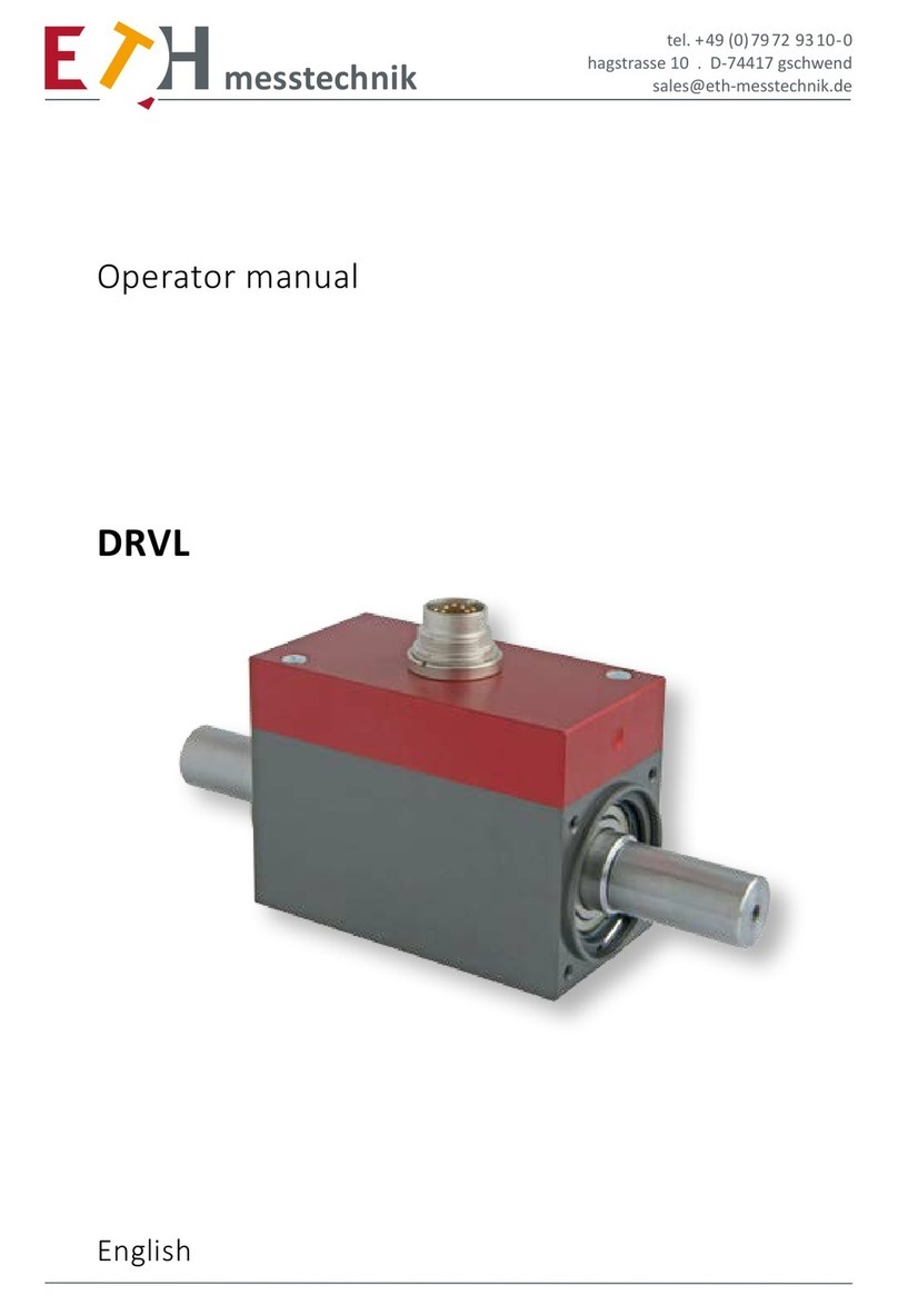
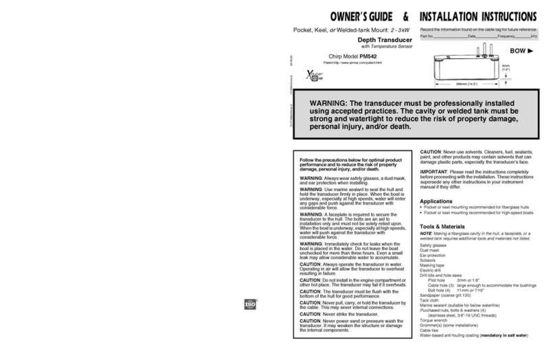
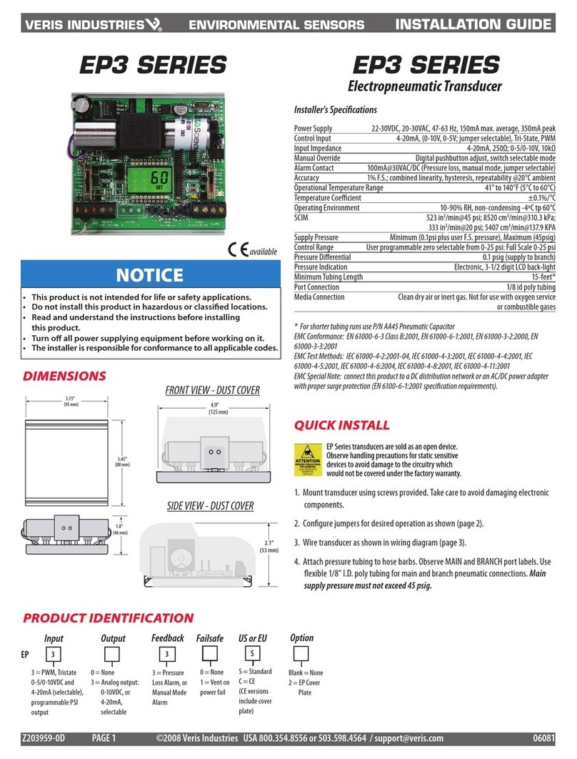
ETH-messtechnik DRVL User manual

tel. +49 (0)79 72 93 10-0
hagstrasse 10 . D-74417 gschwend
Operator manual
English
messtechnik
DRVL
Option „F“
with base/foot

messtechnik gmbh
2
©ETH messtechnik gmbh
This operator manual is not a quality agree-
ment or durability guarantee as set out in
Section 443 of the German Civil Code.
Specification changes, typing and printing
errors reserved.

messtechnik gmbh
3
Inhalt
Important instructions: ...................................................................................................4
1. Preliminaries ...............................................................................................................5
2. Applicability and instructions for use ..........................................................................5
3. Description and functionality of the device ...............................................................6
3.1 Torsional shaft .....................................................................................................6
3.2 Enclosure .............................................................................................................6
3.3 Principle of operation .........................................................................................6
3.4 Disturbances and their compensation.................................................................7
4. Conditions on location ................................................................................................ 8
4.1 Ambient temperature..........................................................................................8
4.2 Moisture and dust................................................................................................8
4.3 Chemical effects...................................................................................................8
4.4 Deposits ..............................................................................................................8
5. Mechanical installation................................................................................................9
5.1 Precautions to be taken when assembling the transducer..................................9
5.2 General assembly guidelines ...............................................................................9
5.3 Additional parts and suggested values for the installation .....................................10
6. The measurement-chain setup..................................................................................11
7. Electrical connection .................................................................................................12
7.1 Wiring instructions.............................................................................................13
7.2 Connectors.........................................................................................................13
7.3 Pin assignment for the connectors ....................................................................14
7.4 Control activation ..............................................................................................14
7.5 Extension cables ................................................................................................14
7.6 The power supply ..............................................................................................14
8. Pin assignment .........................................................................................................15
8.1 DRVL standard cable ..........................................................................................15
8.2 DRVL robot cable ...............................................................................................16
9. Measurement outputs ..............................................................................................17
10. Recalibration............................................................................................................17
11. Disposal ...................................................................................................................17
12. Datasheet DRVL.......................................................................................................18
12.1 Electrical Specifications....................................................................................18
12.2 Mechanical Dimensions DRVL-F.......................................................................19
12.3 Technical Specifications DRVL ..........................................................................20

messtechnik gmbh
4
Important instructions:
The model DRVL torque transducer can be deployed as a component in a test
bench, for example.
The installation position of the drive and transducer sides should be taken into
account in applications where mass is critical.
Please note that in order to achieve greater sensitivity the transducer
has not been designed with the safety factors 2 to 20 that are common in me-
chanical engineering.
Please pay special attention to the specified overload factors.
Where there is a risk of personal injury or damage to equipment due to mechani-
cal failure leading to breakage, the user of the device must put in place adequate
safety measures (e.g., covers and guards, and overload protections). All applicab-
le accident prevention regulations must be followed.
The torque transducer is not approved for use in hazardous areas.
Opening or disassembling the transducer during the warranty period
will void the warranty.

messtechnik gmbh
5
1. Preliminaries
The torque transducers are made of different shaft materials to suit the loads.
Torque transducers measure torque in the unit Nm.
Please refer to the relevant data sheet for the current technical specifications.
www.eth-messtechnik.de
2. Applicability and instructions for use
The torque transducers measure clockwise and counterclockwise loads. In case
of clockwise load, the output signal is positive.
The full-scale value is printed on the device label.
The torque transducers can measure both static and dynamic torques. The low
masses and high torsional stiffness are particularly beneficial in this context.
Please refer to the data sheet for the specified signal rise for the transducer.
The torque transducers need no maintenance as they are fitted with contactless
outputs. Their electrical outputs can be transmitted to remote test benches,
where they can be displayed, recorded, processed and used for control opera-
tions.
The torque transducers are precision devices and should be handled carefully
when transported and when being installed to prevent them being damaged by
shocks or if they fall to the ground. Torque peaks above the rated overload can
severely damage the torsional shaft. These peaks must be intercepted and absor-
bed if they cannot be avoided.
The limits for the permissible mechanical, thermal and electrical stresses are
detailed in the data sheet. They must be strictly observed. Please consider these
limits when designing, installing and operating the measurement setup.

messtechnik gmbh
6
3. Description and functionality of the device
3.1 Torsional shaft
The torsional shaft is constructed with special aluminum or hardened carbon
steel to suit the full-scale value.
Strain gauges attached to the torsional shaft sense the shaft torsion, which is
proportional to the torque and is within its elastic range. The strain gauges are
arranged as a Wheatstone bridge circuit. The force is transmitted via cylindrical
shaft extensions with smooth shaft extensions or a featherkey as per DIN 6885.
A pulse disk for speed or rotation angle measurement can be fitted to the torsio-
nal shaft if needed. Please refer to the data sheet for more details.
3.2 Enclosure
The enclosure for the torque transducer is made of high-strength aluminum; the
enclosure surface is hard-anodized to protect it. The torsional shaft is supported
in the enclosure with two deep-grooved ball bearings. The transducer can either
be base mounted or flange mounted. An electronics module for conditioning
and analyzing the signal for torque, speed or angle of rotation is installed in the
enclosure.
3.3 Principle of operation
The torsional shaft, and thus the strain gauges, are elastically deformed by the
torsional force. The ohmic resistances of the strain gauges change proportional
to their change in length. The electronics module is connected in series and it
transfers the measurements by means of optical frequency modulation to the
enclosure.
The signal is then converted by the external electronics unit to an analog voltage
that is proportional to the change in frequency. Those signals and frequency
output are available as an electrically isolated signal for further processing.
The pulse disk on the torsional shaft is sampled with an encoder in the enclosure.
Two waveforms are available for analysis: (1) a square wave with 60 pulses/turn
for the speed option, and (2) two square waves offset by 90° with 360 pulses/
turn for the angle of rotation option.The direction of rotation can be detected
with the angle of rotation option. Channel A leads channel B by 90° for clockwise
rotation.

messtechnik gmbh
7
3.4 Disturbances and their compensation
Flexural, axial and radial forces are disturbances and, hence, should be avoided.
We recommend the use of clamping hub couplings. They must be selected to
suit the operating conditions.
Shielded cables should be used for the electrical connections. The electroma-
gnetic compatibility (EMC)of the torque transducers are tested for compliance
with EN 55011:2011.
The immunity of the torque transducers to noise is tested to the following stan-
dards:
• 61000-4-2:2009
• 61000-4-3:2009
• 61000-4-4:2009
• 61000-4-5:2009
• 61000-4-6:2009
• 61000-4-8:2009

messtechnik gmbh
8
4. Conditions on location
4.1 Ambient temperature
For best results, the device must be operated within the nominal temperature
range. The best operating conditions are constant and, if necessary, slowly
changing temperatures. The specified temperature errors apply if the tempera-
ture does not change faster than 5K/h. One-sided thermal radiation or cooling
should be avoided and appropriate technical preventive measures taken, if
necessary.
4.2 Moisture and dust
The torque transducers comply with protection type rating IP40 as per DIN
40050.
Note: There should be no moisture inside the transducer connector
4.3 Chemical effects
The torque transducers are not protected against chemical effects. They must
not be used in caustic or corrosive environments.
4.4 Deposits
Dirt, dust or other foreign substances should not accumulate so that they can
enter the bearing or the connectors.

messtechnik gmbh
9
5. Mechanical installation
5.1 Precautions to be taken when assembling the transducer
• Handle the transducer carefully.
• IMPORTANT!
While assembling the couplings, don’t overload the transducer, even
temporarily. It is highly suggested to connect the transducer electri
cally first and monitor the torque signal in order to prevent exceeding
the torque range!
• Axial and radial misalignments must be avoided.
• Make sure the enclosure is correctly connected electrically to
the grounded parts.
5.2 General assembly guidelines
The drive and transducer sides should not be swapped, otherwise measurements
(readings) will be invalidated during accelerations, for example.
When reading the device label, the drive side is on the right and the transducer
side on the left of the transducer. There is a small cavity in the cover on the mea-
surement side.
Flexural, axial and radial forces are disturbances that cause incorrect measure-
ments
Be careful with the thermal expansion of the assembly.
Measuring side mark
Direction of rotation for positive indication

messtechnik gmbh
10
5.3 Additional parts and suggested values for the installation
Model DRVL-F DRVL-I-F DRVL-Ib-F DRVL-II-F DRVL-III-F DRVL-IV-F DRVL-V-F DRVL-VI-F
Addional parts:
1. Hexagon socket
head cap screw
(DIN912-8.8-Zn)
M5x25 M5x25 M6x30 M6x30 M8x35 M10x45 M12x55 M16x80
2. Fan washer
(DIN6798 A-Zn) 5,3 5,3 6,4 6,4 8,4 10,5 13 17
3. Plain washer
(DIN433-4.8-Zn) 5,3 5,3 6,4 6,4 8,4 10,5 13 17
4. Straight pin
(DIN6325) 4m6x8 4m6x8 5m6x10 5m6x10 6m6x12 8m6x16 10m6x20 12m6x24
5. Parallel key
(DIN6885 A) 6x6x50 6x6x50 8x7x60 8x7x60 10x8x60 10x8x60 10x8x80 10x8x100
Suggested
values for the
installaon:
Maximum fastening torque of the screws at the base onto steel (Nm)
5,0 5,0 8,6 8,6 21,0 40,8 71,4 190,0
Maximum fastening torque of the screws at the base onto aluminum (Nm)
5,8 5,8 9,9 9,9 24,1 40,8 82,3 164,5
Maximum fastening torque of the screws onto the ange (Nm)
0,6 1,0 1,0 1,0 2,6 8,6 -- --
Minimum installaon depth of the straight pins into the sensor (mm)
4 4 5 5 6 8 10 12

messtechnik gmbh
11
6. The measurement-chain setup
A measurement chain is required for the transducer to take measurements.
The measurement chain consists of:
• a torque transducer
• a connection cable
• a power supply and display unit
A power supply is required to supply the transducer with the necessary opera-
ting voltage. The transducer is fitted with a measurement amplifier (hence, no
other amplifier is needed). The measurement data can be transmitted to a lap-
top, for example, or displayed and analyzed with power supply and display units.

messtechnik gmbh
12
7. Electrical connection
The electrical connection of a torque transducer with a 12-pin connector

messtechnik gmbh
13
7.1 Wiring instructions
Electrical and magnetic fields often disturb the measurement circuit. These dis-
turbances typically emanate from power lines running parallel to the test cables,
but they can also come from nearby contactors or electric motors. Interference
or noise voltages can be injected into the circuit as well electrically, especially if
the measurement chain is grounded at many points. This can give rise to potenti-
al differences.
Please note the following instructions.
• Use only shielded, and low-capacitance cables.
• Connect the supply voltage correctly
• Do not lay the device cable parallel to heavy-duty or control lines.
• Avoid leakage fields from transformers, motors and contactors.
• Do not ground the transducer, analyzer and indicating unit
at multiple points.
Connect all devices in the measurement chain to the same
protective conductor.
7.2 Connectors
The transducers are fitted with a 12-pin integrated connector Binder model 680.

messtechnik gmbh
14
7.3 Pin assignment for the connectors
The pin assignments for the connectors are detailed on the following pages.
The transducer outputs the measurements as an electrically isolated signal. The
ground potentials should not be directly bridged at the transducer, as this could
lead to incorrect measurements, depending on the length of the cable to the
power supply and display unit. Instead, they can be bridged at the power supply
and display unit, if necessary.
7.4 Control activation
The “control activation” is used to test the transducer. This emits its maximum
signal of e.g. 10 V and 15 kHz (with right-hand load). The control level is 4.5 V up
to the supply voltage; the reference ground point is the supply ground.
Attention: Note the tare!
7.5 Extension cables
Extension cables must be shielded and have low capacitance. We recommend
you use our cable, as it meets these requirements. Pay particular attention to the
connectors and ensure good insulation when using cable extensions. The cable
cross-section should be sufficiently large to ensure adequate power reaches the
transducer. There is no need to recalibrate the transducer when extending the
cable.
7.6 The power supply
The torque transducer is fitted with a universal voltage input for the voltage ran-
ge 10 V - 28.8 V. If the voltage goes above 28.8 V, the internal suppressor circuit
is activated and the power supply is shorted.

messtechnik gmbh
15
8. Pin assignment
8.1 DRVL standard cable
AK12.4 for active sensors
12-pin connector
(Top view of transducer connector)
External EMC circuit
A 100 nF / 50 V ceramic capacitor can be soldered between pins C - D at the
analyzer to suppress conductor-borne disturbances.
PIN D (torque ground) and PIN E (power supply ground) are electrically isolated
internally, short at the power source if required (not at the transducer).
Pin Colour Occupancy DRVL
A Green Frequency output
B Red / Blue Angle exit track B = 90 °
C Yellow Moment exit
D White Moment mass
EGrey Supply + angle / speed ground
F Pink Supply + 9… 28V
G Grey / Pink Speed / angle output track A = 0 °
H Purple Memory chip
J Black Message ready for operation
KRed Control entrance
L Brown Inverted frequency output
M Blue Voltage reference angle signal

messtechnik gmbh
16
8.2 DRVL robot cable
AK12.5 for active sensors
12-pin connector
(Top view of transducer connector)
External EMC circuit
A 100 nF / 50 V ceramic capacitor can be soldered between pins C - D at the
analyzer to suppress conductor-borne disturbances.
PIN D (torque ground) and PIN E (power supply ground) are electrically isolated
internally, short at the power source if required (not at the transducer).
Pin Colour Occupancy DRVL
A Black Frequency output
BRed Angle exit track B = 90 °
C Brown Moment exit
D White Moment mass
E Yellow Supply + angle / speed ground
F Purple Supply + 9… 28V
G Green Speed / angle output track A = 0 °
H Pink Memory chip
JGrey Message ready for operation
K Grey/Pink Control entrance
L Blue/Red Inverted frequency output
M Blue Voltage reference angle signal

messtechnik gmbh
17
9. Measurement outputs
The transducer outputs a 0 – 10 V DC voltage that is proportional to the tor-
que. The output voltage is positive for clockwise torque, and negative for
counterclockwise torque. The transducer outputs a 10 kHz ± 5 kHz differential
frequency signal (RS422), as well.
The torque sensor has a permitted zero point deviation of ± 50 mV / ± 50 Hz. A
taring option must be provided for precise measurements.
Each of the speed and angle-of-rotation outputs has an active driver in the
system. The speed, angle and ready outputs deliver a TTL signal in the absence of
an external voltage reference.
The device also outputs a ready signal (Pin J): logic HIGH means the device is
ready, LOW means there is a fault in the device.
If a higher voltage output is needed, for PLC inputs, for example, a voltage
reference can be set through pin M. The voltage reference tolerates a 5 V - 24 V
voltage range.
10. Recalibration
We recommend, regardless of use, a recalibration (deadline see certificate) in
the house of ETH.
11. Disposal
The transducer along with the measuring cable can be returned free of charge to
us for disposal. As soon as you have packaged the transducer, send us an e-mail
at sales@eth-messtechnik.de. We will then instruct our parcel service to pick it
up.
We are sorry, but we cannot accept any goods sent to us unannounced and
freight-collect.

messtechnik gmbh
18
Supply voltage: 10 - 28,8 V DC
Power consumption: at Ub 12 V approx. 180 mA (switching converter 2.2 W)
Rise time 10-90 %: 2 ms (optional 400 μs)
Limit frequency -3 dB: 200 Hz (optional 1 kHz)
Voltage output: Output frequency:
Voltage output: 0 ± 10 V 10 kHz ± 5 kHz (RS422)
Resolution: 16 bit ≙0,38 mV 16 bit ≙0,19 mHz
Max. output range: ± 11 V ± 6,3 KHz
Internal resistance: 100 Ω _
Ripple: < 100 mVss _
Nonlinearity/max. measurement error (of full scale)
DRVL: 0,15 % (optional 0,1 % )
DRVL-
I
to DRVL-
VI
: 0,1 % (optional 0,05%)
0,15 % (optional 0,1 % )
0,1 % (optional 0,05 % )
Hysteresis 0,1 % 0,1 %
Deviation at zero point: ≤ 50 mV ≤ 50 Hz
Operating temperature: 0 - 60 °C
Compensated temperature range: 5 - 45 °C
Temperature error
Zero point:
Sensitivity:
0,02 % / K
0,01 % / K
Mechanical overload: 100 %
Internal protection: IP 40 (DIN 40050)
Connection: 12pin-connector
Interference emission
Basic standard
EN55011 Limit class B
Frequency range
150 kHz - 6 GHz
Immunity to interference
Basic standard
EN61000-4-2:2009 Electrostatic discharge (ESD)
EN61000-4-2:2009 Electrostatic discharge (ESD)
EN61000-4-3:2009 Electromagnetic fields
EN61000-4-4:2009 Bursts
EN61000-4-5:2005 Surge voltages
EN61000-4-6:2009 Conductor-borne RF disturbances
EN61000-4-8:2005 Power frequency magnetic fields
A: Deviation of outputs during the test < 0.3 % of full scale
B: Deviation of outputs during the test > 0.3 % of full scale
Speed Option (n) Angle Option (w)
max rev.: ≤ 37.000 1/min* ≤ 20.000 1/min*
Output: TTL or over voltage on pin 5 V - 24 V
Impedance: 22 Ω 22 Ω
Imax: 20 mA 20 mA
Pulses/rev.: 60 2 x 360
Resolution: -- 1°
Phase shift: -- Channel A 90° at right spin of propulsion side
* The values are valid for ETH test cables ≤ 10 m, the maximum permissible speed of the sensor must be observed.
Testing accuracy coupling Result
4 kV
4 kV
10 V/m
2 kV
1 kV
10 V/m
30 A/m
direct
indirect
indirect
indirect
direct
indirect
indirect
A
A
A
A
B
A
A
12. Datasheet DRVL
12.1 Electrical Specifications

messtechnik gmbh
19
12.2 Mechanical Dimensions DRVL-F
Typ DRVL DRVL-IDRVL-IbDRVL-II DRVL-III DRVL-IV DRVL-VDRVL-VI
Mess-
bereiche:
(± 0 - ... Nm)
0,02
0,05
0,10
0,05
0,1
0,2
0,5
1
2 1
2
5
10
5
10
20
30
50
50
100
150
200
300
500
1000
1300
1500
2000
3000
4000
5000
10.000
15.000
20.000
Abmessungen: (andere Messbereiche auf Anfrage; Allgemeintoleranzen nach DIN 2768-m)
L (mm) 82 89 95 110 145 170 270 320 355
B (mm) 56 60 78 78 98 158 208 298
B1 (mm) 32 28 36 42 56 88 105 168
B2 (mm) 24 (→ LK) (→ LK) (→ LK) (→ LK) (→ LK) -- --
H (mm) 78 85 85 82 90 172 228,5 316
H1 (mm) 45 45 45 45 45 112 160 215
H2 (mm) 12 12 15 15 15 20 30 40
Ø D1 g6 (mm) 3 8 8 10 15 26 45 70 110
Ø D2 g6 (mm) 3 5 6 10 15 26 45 70 110
Ø D3-0,1 (mm)
15 27 32 38 54 80 -- --
Ø LK ± 0,1 (mm)
(→ B2/H3) 32 38 45 65 98 -- --
L1 63 62 68 79 72 84 95 121
L2 7,5 11 14 18 30 45 85 110 115
L3 7,5 10 14 18 30 45 85 110 115
L4 67 66 72 83 78 90 -- --
N1H8 (mm) 6 6 8 8 10 10 10 10
N2 (mm) 2,8 2,8 3,3 3,3 3,3 3,3 3,3 3,3
N3 (mm) 50 50 60 60 60 60 80 100
S1 5,5 5,5 6,6 6,6 911 13 17
S2 50 50 50 65 55 65 70 90
S3 44 44 58 58 76 124 156 233
Ø Z E8
4
4 5 5 6
810
12
M
M2,5 x 5M3 x 6 M3 x 6 M3 x 6 M4 x 8 M6 x 12 -- --
P (DIN 6885)
optional -- -- 2x
A3x3x14
2x
A5x5x25
2x
A8x7x40
4x
A14x9x80
4x
A20x12x100
--
Gewicht ca. (g)
400 400 600 900 1600 6600 15.000 43.000
n max (
min-1
)
20.000 37.000 26.000 19.000 13.500 7900 6300 4000

messtechnik gmbh
20
Model Torque range
(Nm)
Spring constant C
(Nm/rad)
Mass moment of
inertia J (g x cm²)
Rated axial load
(N) *
Rated radial load
(N) *
DRVL
0,02 16 7 35 30
0,05 16 7 35 30
0,1 16 7 35 30
DRVL-I
0,05 20 10 105 2
0,1 35 10 140 3
0,2 35 10 140 3
0,5 45 10 160 4
1 90 10 210 7
2 135 10 210 13
DRVL-Ib
1 255 30 630 10
2 255 30 630 10
5 715 30 725 25
10 1320 30 725 50
DRVL-II
5 960 100 1200 15
10 2115 100 1300 30
20 3955 100 1300 60
30 5340 105 1300 100
50 6700 105 1300 155
DRVL-III
50 17 x 103775 1800 125
100 30 x 103785 1800 215
150 45 x 103800 1800 340
200 54 x 103810 1800 450
300 67 x 103840 1800 650
DRVL-IV
500 260 x 1039935 4150 650
1000 387 x 10310.140 4150 1275
1300 429 x 10310.285 4150 1650
1500 449 x 10310.380 4150 1700
DRVL-V
2000 1,45 x 10663 x 1034800 1950
3000 1,85 x 10664 x 1034800 2930
4000 2,10 x 10664 x 1034800 3880
5000 2,30 x 10665 x 1034800 4000
DRVL-VI
10.000 8,20 x 106440 x 10311.800 8895
15.000 10,45 x 106448 x 10311.800 9830
20.000 11,80 x 106546 x 10311.800 9830
12.3 Technical Specifications DRVL
Ordering code system
Available Accessories
Supply and display unit: GMV2
ValueMasterBase
Cables
Couplings
A Standard
n Speed op�on
w Angle op�on
- - --
0
Standard accuray
1
Op�on higher accuray
K Op�on keyway
Model/size
Torque range (Nm)
DRVL
F Op�on base
--
071 Op�on limit frequency 1kHz
* The values for axial and radial load apply to the non-fixed case
Other manuals for DRVL
1
This manual suits for next models
8
Table of contents
Other ETH-messtechnik Transducer manuals
Popular Transducer manuals by other brands
Balluff
Balluff BTL6-V5 V-M PF-S115 Series user guide
S&P
S&P TDP-D quick start guide
MKS
MKS 905 MicroPirani Design guide
S+S Regeltechnik
S+S Regeltechnik PREMASGARD 711x Series Operating Instructions, Mounting & Installation
Endress+Hauser
Endress+Hauser Cerabar PMP23 operating instructions

Petroline-A
Petroline-A TP-140D Operation manual
