manuals.online logo
Brands
  1. Home
  2. •
  3. Brands
  4. •
  5. M-system
  6. •
  7. Transducer
  8. •
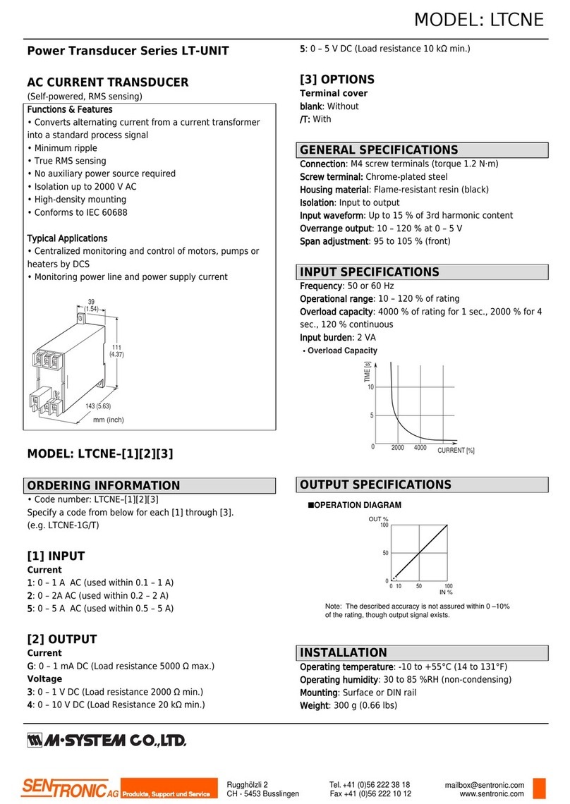
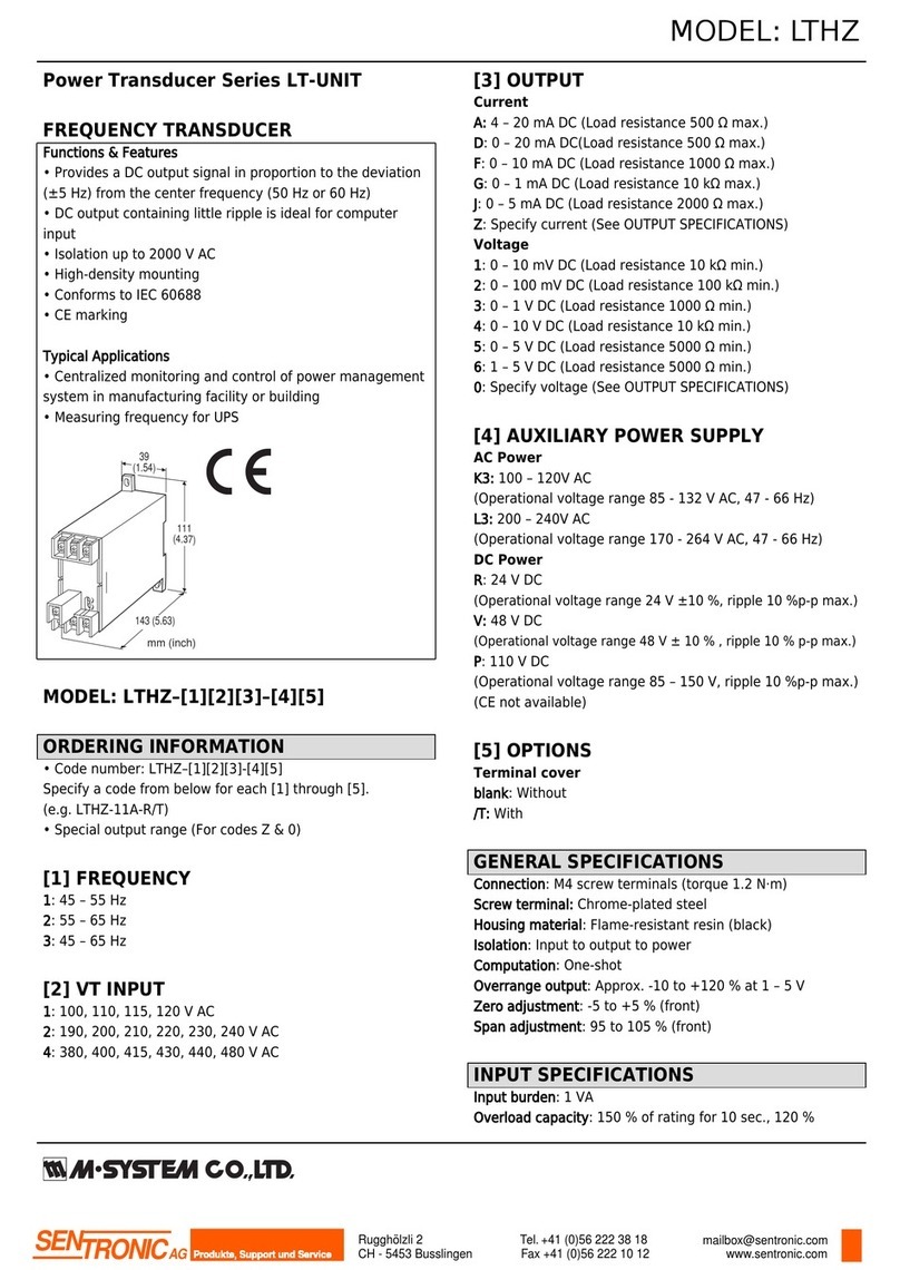
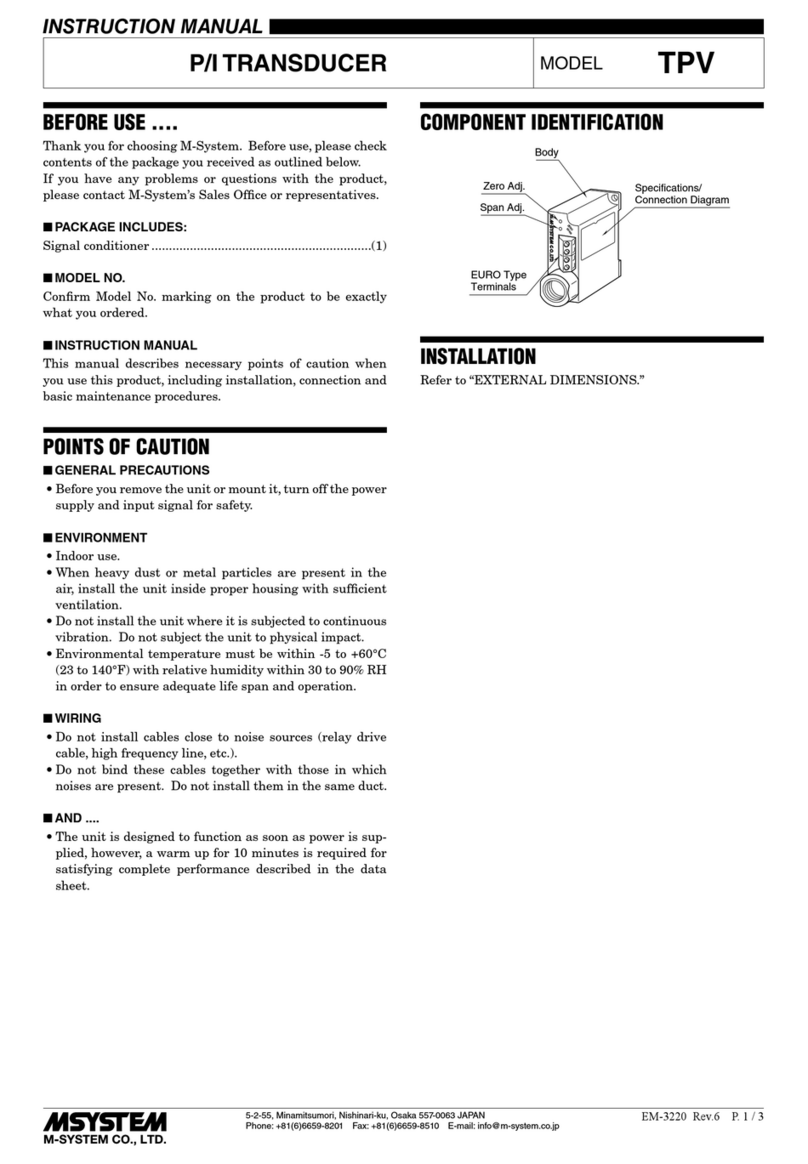
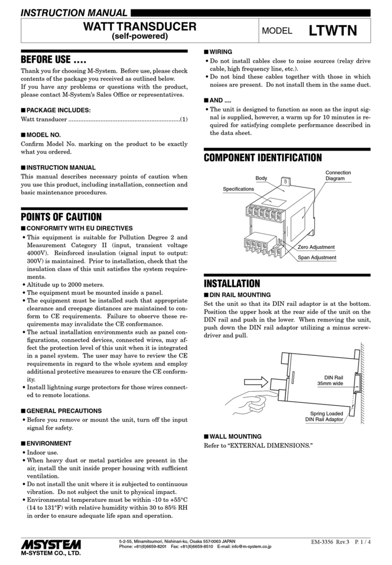
  9. M-system 18RP User manual

M-system 18RP User manual

5-2-55, Minamitsumori, Nishinari-ku, Osaka 557-0063 JAPAN
Phone: +81(6)6659-8201 Fax: +81(6)6659-8510 E-mail: info@m-system.co.jp
EM-1867 P. 1 / 3
INSTRUCTION MANUAL
BEFORE USE ....
Thank you for choosing M-System. Before use, please check
contents of the package you received as outlined below.
If you have any problems or questions with the product,
please contact M-System’s Sales Office or representatives.
■PACKAGE INCLUDES:
Signal conditioner ...............................................................(1)
■MODEL NO.
Confirm Model No. marking on the product to be exactly
what you ordered.
■INSTRUCTION MANUAL
This manual describes necessary points of caution when
you use this product, including installation, connection and
basic maintenance procedures.
POINTS OF CAUTION
■POWER INPUT RATING & OPERATIONAL RANGE
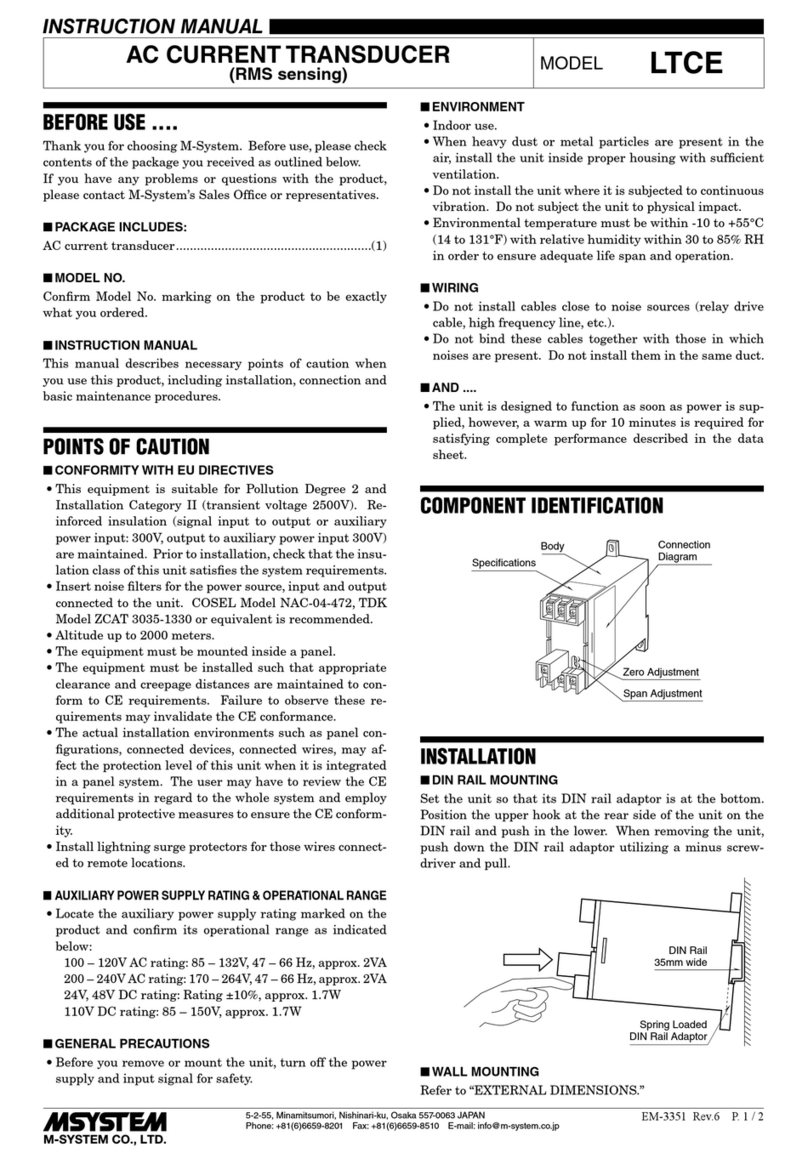
• Locate the power input rating marked on the product and
confirm its operational range as indicated below:
24V DC rating: 24V ±10%, approx. 80mA
■GENERAL PRECAUTIONS
• Before you remove the unit or mount it, turn off the power
supply and input signal for safety.
■ENVIRONMENT
• Indoor use.
• When heavy dust or metal particles are present in the
air, install the unit inside proper housing with sufficient
ventilation.
• Do not install the unit where it is subjected to continuous
vibration. Do not subject the unit to physical impact.
• Environmental temperature must be within -5 to +55°C
(23 to 131°F) with relative humidity within 30 to 90% RH
in order to ensure adequate life span and operation.
■WIRING
• Do not install cables close to noise sources (relay drive
cable, high frequency line, etc.).
• Do not bind these cables together with those in which
noises are present. Do not install them in the same duct.
■AND ....
• The unit is designed to function as soon as power is sup-
plied, however, a warm up for 10 minutes is required for
satisfying complete performance described in the data
sheet.
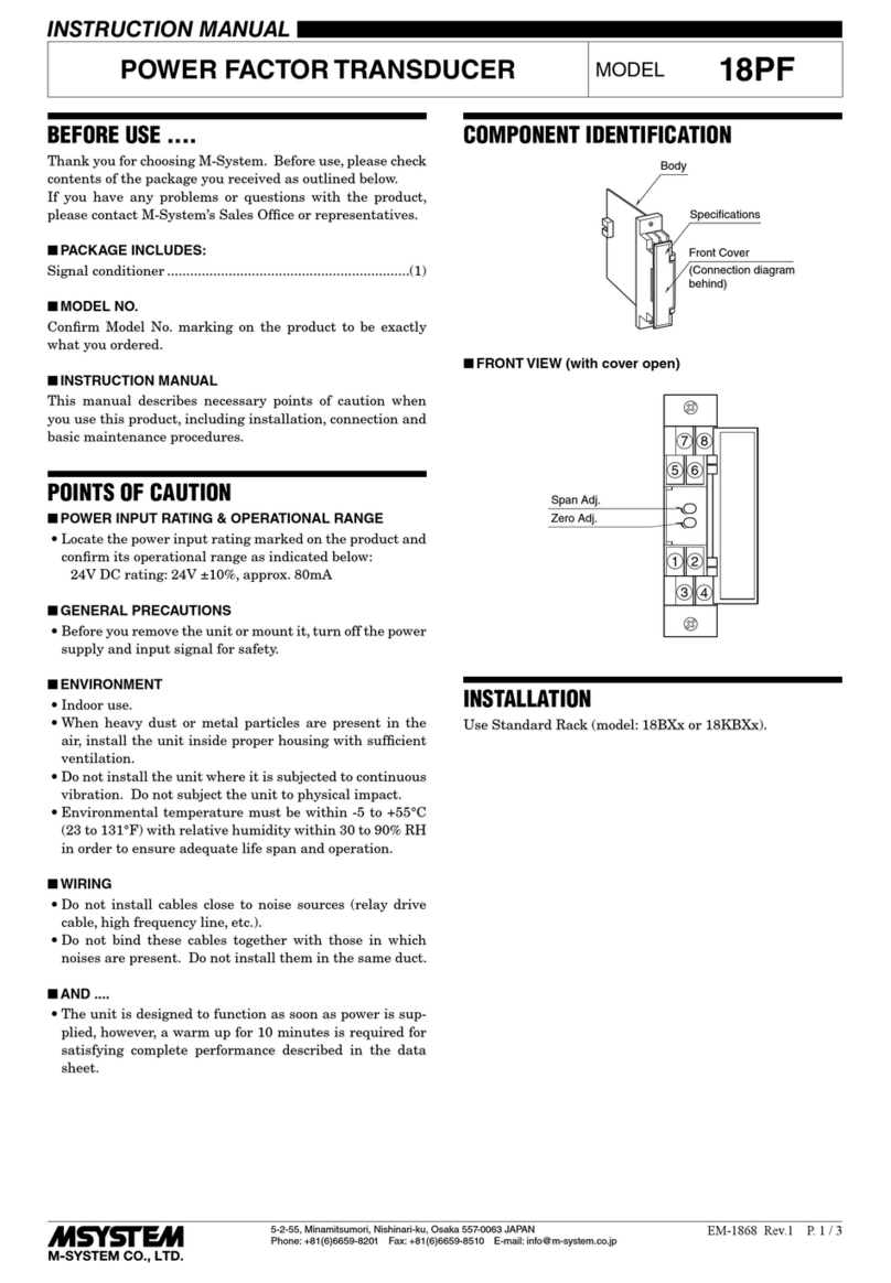
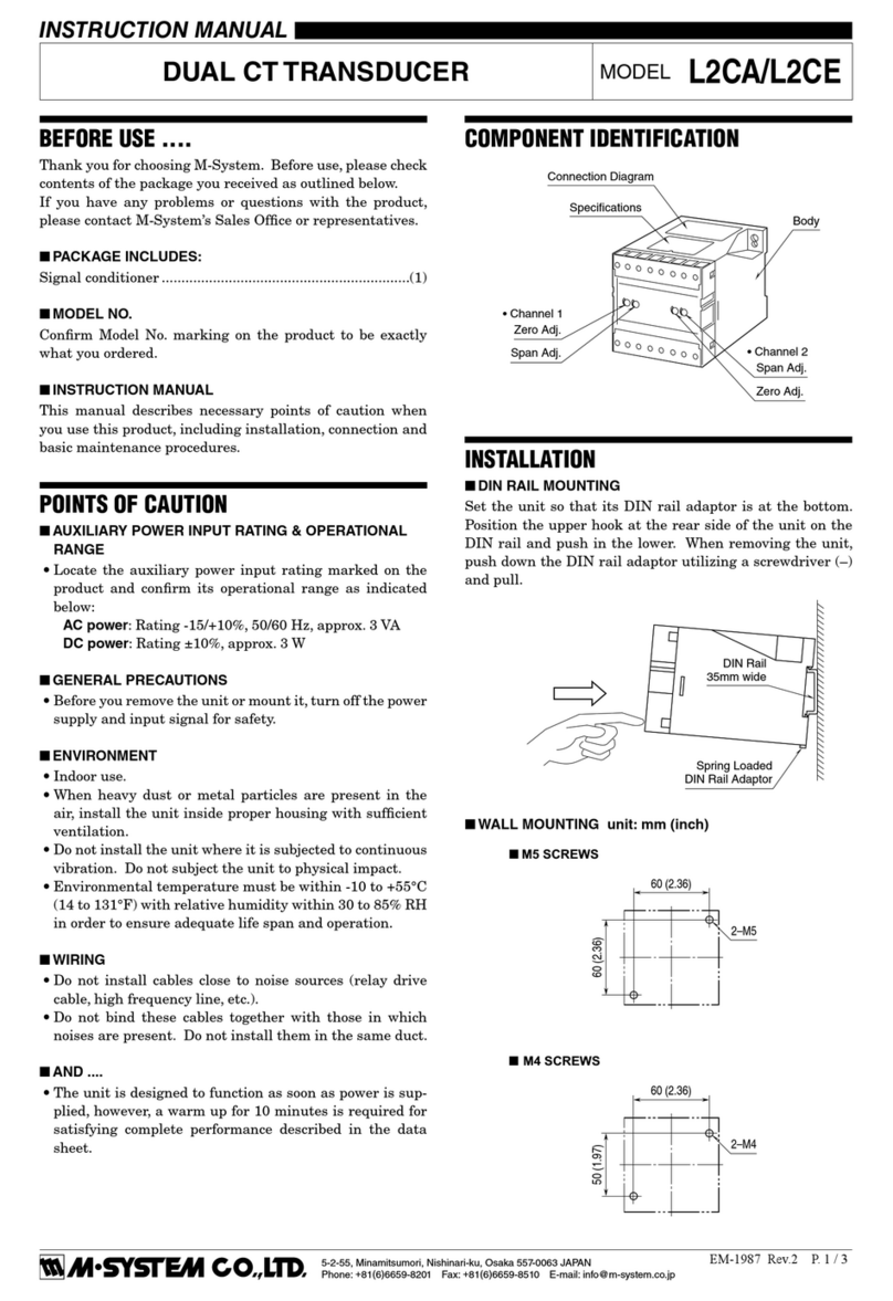
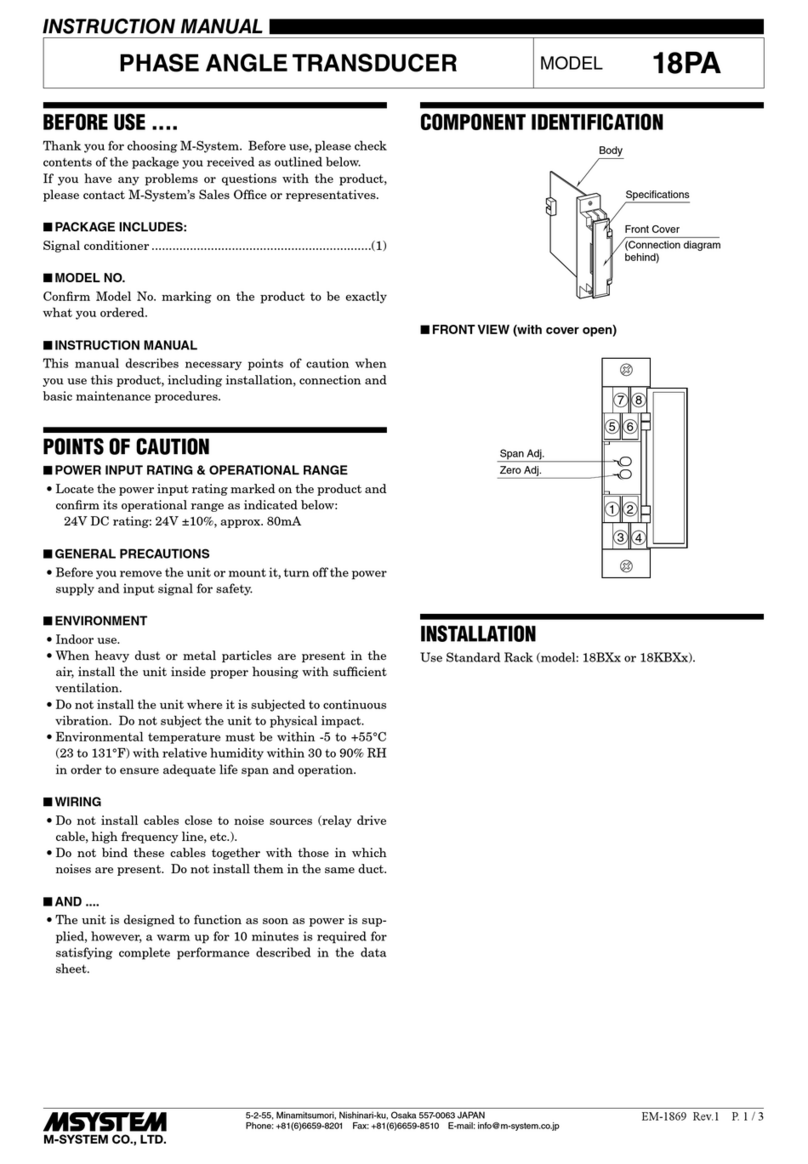
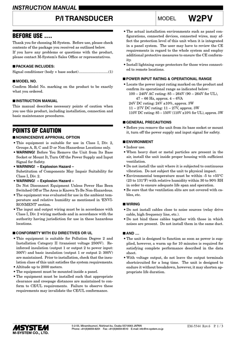
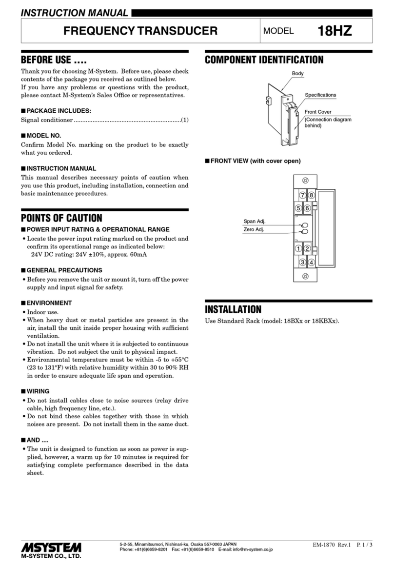
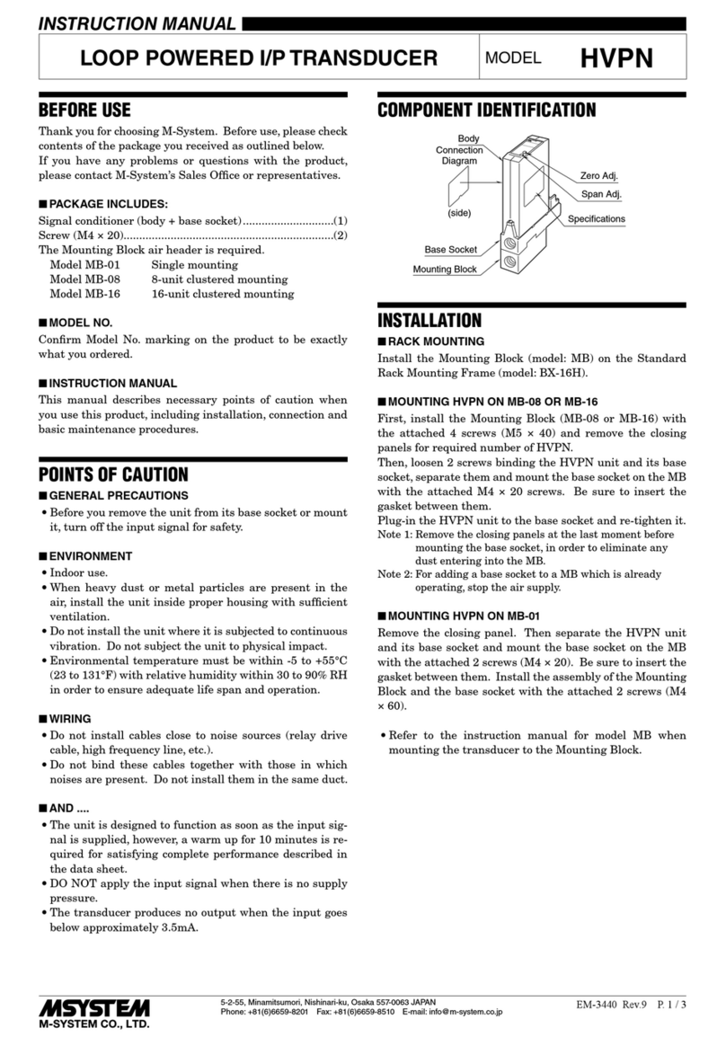
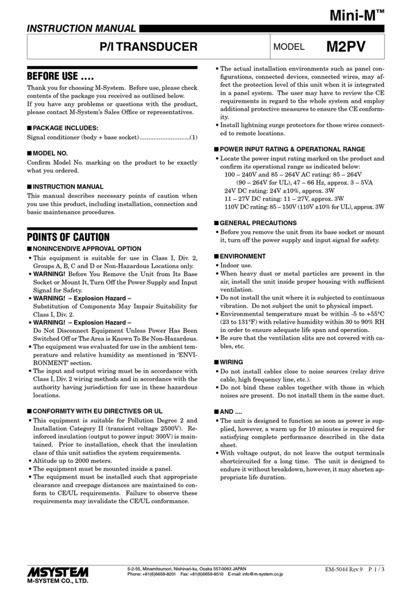
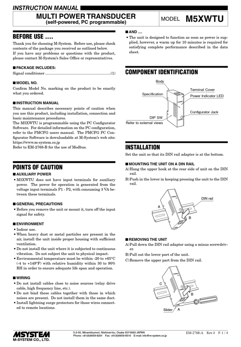
COMPONENT IDENTIFICATION
Body
Specifications
Front Cover
(Connection diagram
behind)
■FRONT VIEW (with cover open)
Span Adj.
Zero Adj.
1
78
56
2
34
INSTALLATION
Use Standard Rack (model: 18BXx or 18KBXx).
VAR TRANSDUCER MODEL 18RP
18RP
5-2-55, Minamitsumori, Nishinari-ku, Osaka 557-0063 JAPAN
Phone: +81(6)6659-8201 Fax: +81(6)6659-8510 E-mail: info@m-system.co.jp
EM-1867 P. 2 / 3
TERMINAL CONNECTIONS
Connect the unit as in the diagram below or refer to the connection diagram behind the front cover.
■EXTERNAL DIMENSIONS unit: mm (inch)
110 (4.33 )
93 (3.66)
24 (.94)
7 (.28)
78 (3.07)32 (1.26)
8–M3.5
SCREW
7 (.28)
2–M3
SCREW
■CONNECTION DIAGRAM
P2V
P1U
v
u
VT
P3
1L
1S
3L
3S
5
7
6
1
3
4
2
CONNECTOR
OUTPUT 1
OUTPUT 2
POWER
ll
LOAD
123
SOURCE
FUSE
k
CT
L
K
k
L
K
3-PHASE/3-WIRE
■
Vv
Uu
■TERMINAL ASSIGNMENTS
12
34
78
56
18RP
5-2-55, Minamitsumori, Nishinari-ku, Osaka 557-0063 JAPAN
Phone: +81(6)6659-8201 Fax: +81(6)6659-8510 E-mail: info@m-system.co.jp
EM-1867 P. 3 / 3
WIRING INSTRUCTIONS
■SCREW TERMINAL
Torque: 0.8 N·m
CHECKING
1) Terminal wiring: Check that all cables are correctly con-
nected according to the connection diagram.
2) Power input voltage: Check voltage supplied to the rack
(model: 18BXx or 18KBXx). For the DC power source, be
sure that the ripple level is within 10% p-p.
3) Input: Calculate the calibration range and check that the
result is within the usable range.
Calibration Range [var] = Measuring Range
(VT Ratio) × (CT Ratio)
4) Output: Check that the load resistance meets the de-
scribed specifications.
ADJUSTMENT PROCEDURE
This unit is calibrated at the factory to meet the ordered
specifications, therefore you usually do not need any cali-
bration.
For matching the signal to a receiving instrument or in case
of regular calibration, adjust the output as explained in the
following.
■HOW TO CALIBRATE THE OUTPUT 1
Use a signal source and measuring instruments of sufficient
accuracy level. Turn the power supply on and warm up for
more than 10 minutes.
1) ZERO: Apply 0% input and adjust output to 0%.
2) SPAN: Apply 100% input and adjust output to 100%.
3) Check ZERO adjustment again with 0% input.
4) When ZERO value is changed, repeat the above proce-
dure 1) – 3).
5) No need of adjustments for the Output 2.
MAINTENANCE
Regular calibration procedure is explained below:
■CALIBRATION
Warm up the unit for at least 10 minutes. Apply 0%, 25%,
50%, 75% and 100% input signal. Check that the output
signal for the respective input signal remains within accu-
racy described in the data sheet. When the output is out of
tolerance, recalibrate the unit according to the “ADJUST-
MENT PROCEDURE” explained earlier.
LIGHTNING SURGE PROTECTION
M-System offers a series of lightning surge protector for
protection against induced lightning surges. Please contact
M-System to choose appropriate models.

Other M-system Transducer manuals

M-system Mini-M M2PV User manual

M-system

M-system Mini-M M2PV User manual

M-system TPV User manual

M-system

M-system TPV User manual

M-system LT-UNIT Series User manual

M-system

M-system LT-UNIT Series User manual

M-system L3PK User manual

M-system

M-system L3PK User manual

M-system HVPN User manual

M-system

M-system HVPN User manual

M-system M5XWTU User manual

M-system

M-system M5XWTU User manual

M-system 18PV User manual

M-system

M-system 18PV User manual

M-system PV User manual

M-system

M-system PV User manual

M-system 18HZ User manual

M-system

M-system 18HZ User manual

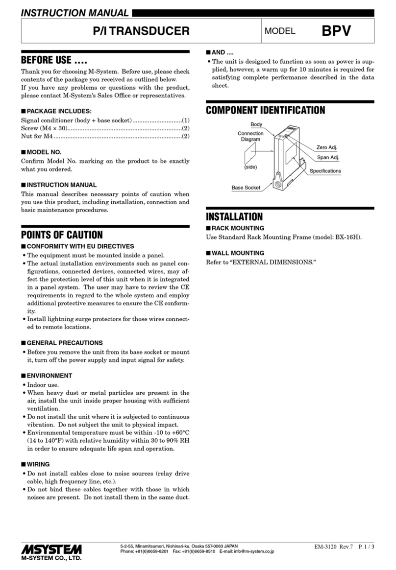
M-system BPV User manual

M-system

M-system BPV User manual

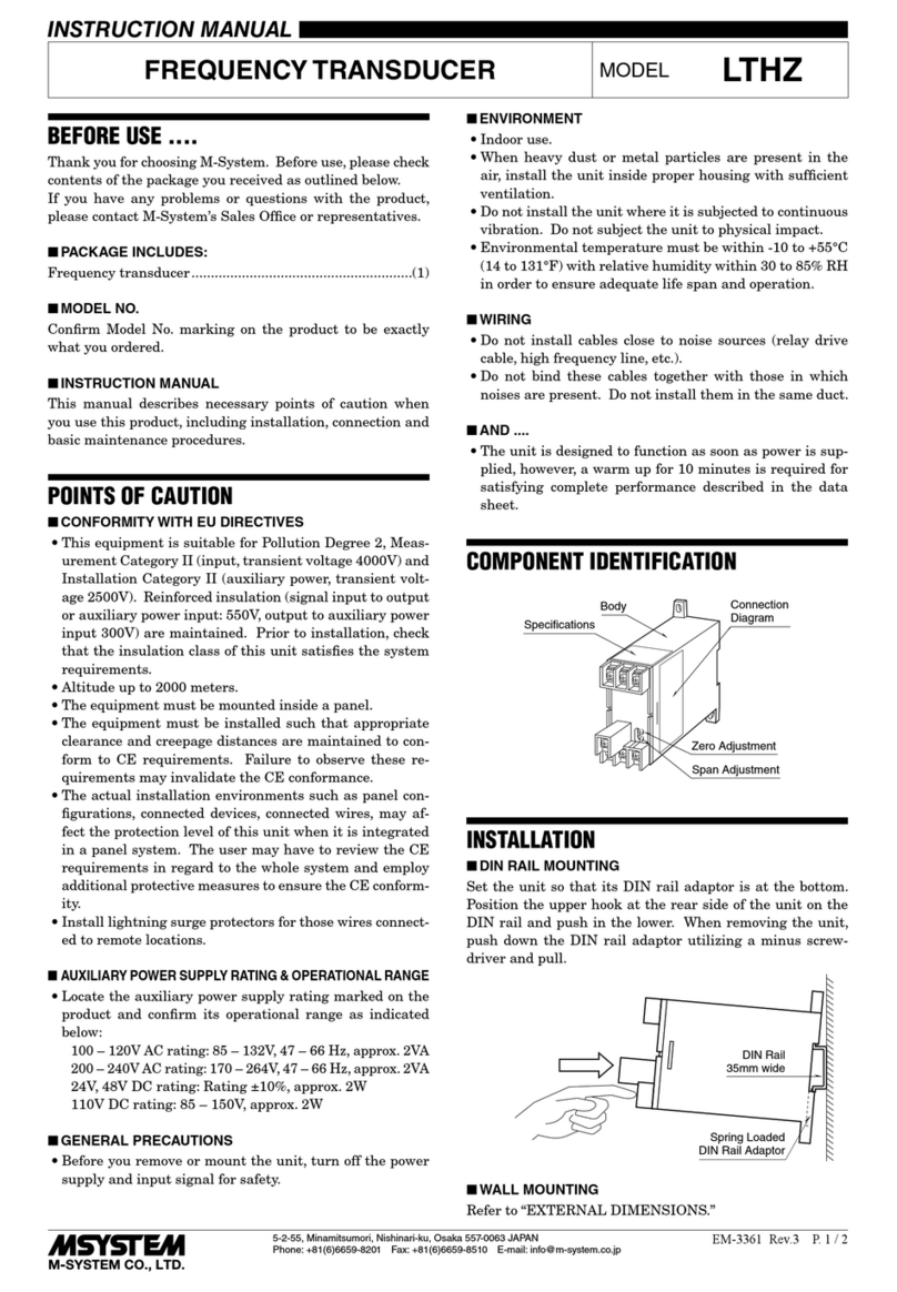
M-system LTHZ User manual

M-system

M-system LTHZ User manual

M-system 18PF User manual

M-system

M-system 18PF User manual

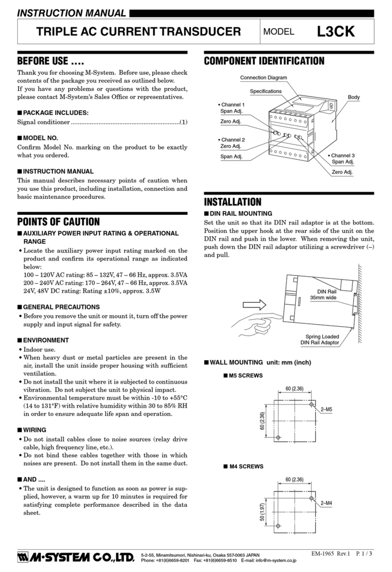
M-system L3CK User manual

M-system

M-system L3CK User manual

M-system L2CA User manual

M-system

M-system L2CA User manual

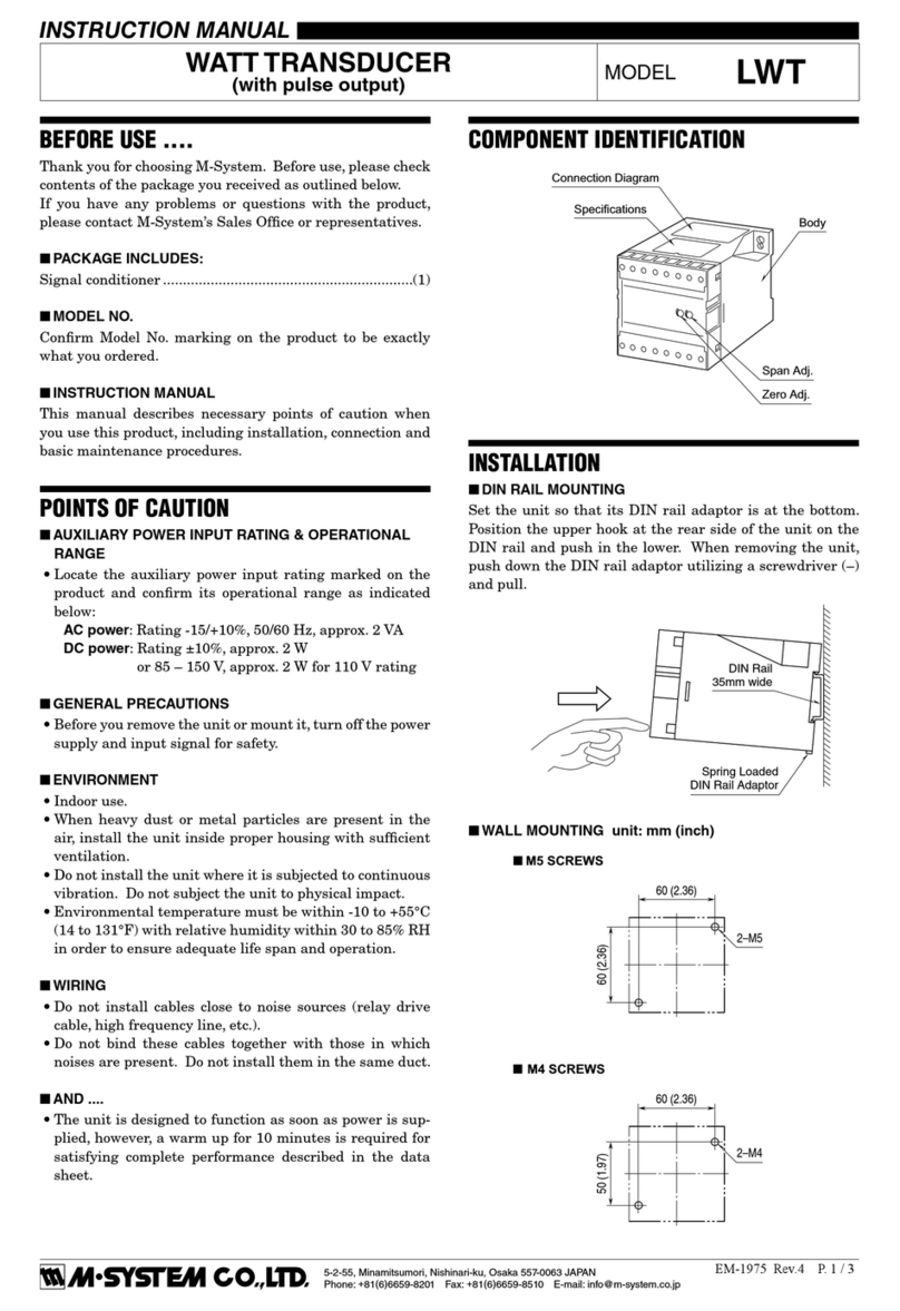
M-system LWT User manual

M-system

M-system LWT User manual

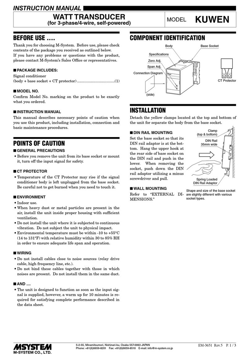
M-system KUWEN User manual

M-system

M-system KUWEN User manual

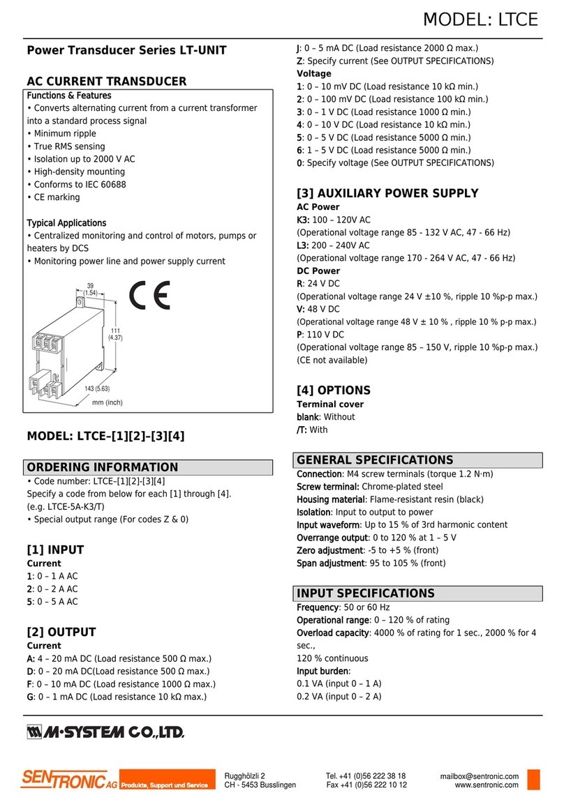
M-system LTCE User manual

M-system

M-system LTCE User manual
M-system W2PV User manual

M-system

M-system W2PV User manual

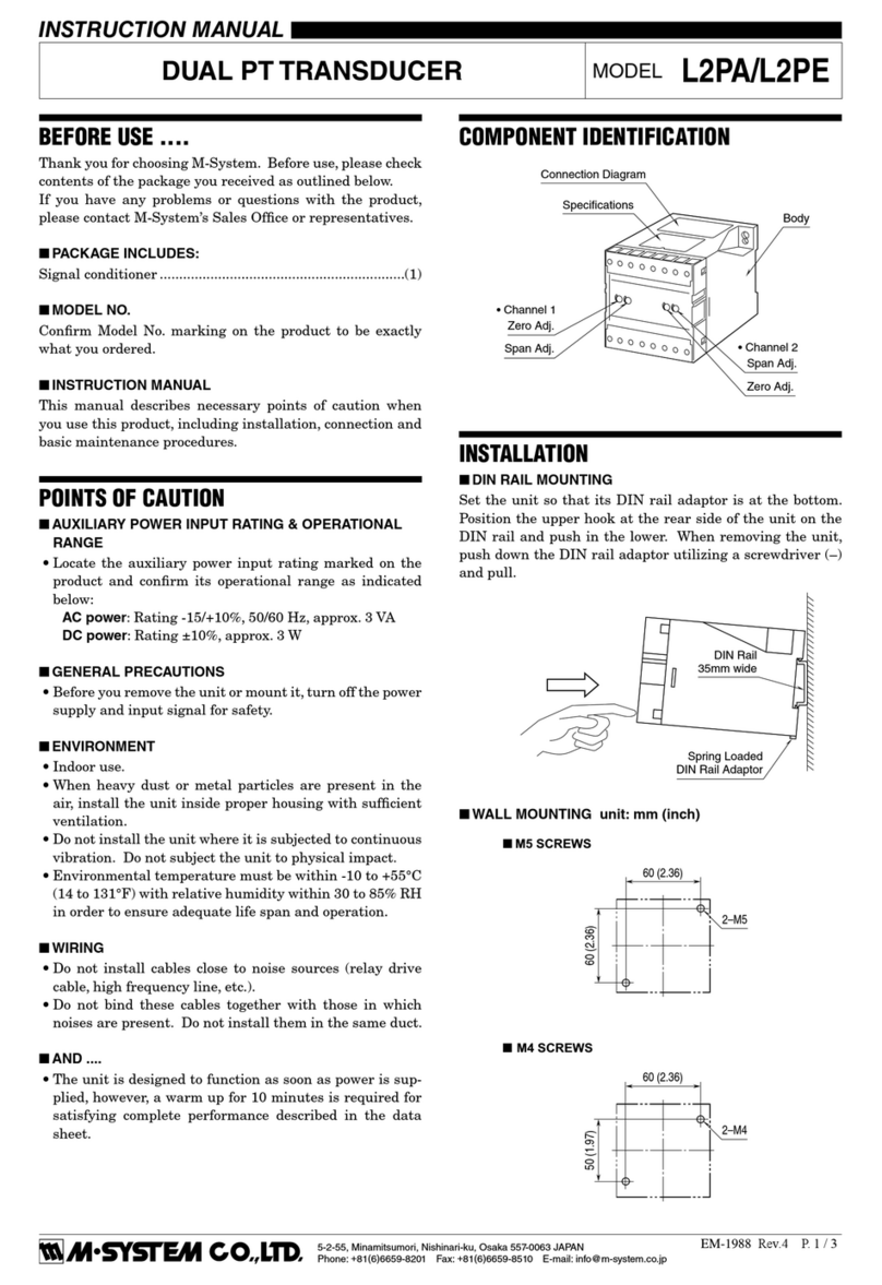
M-system L2PA User manual

M-system

M-system L2PA User manual

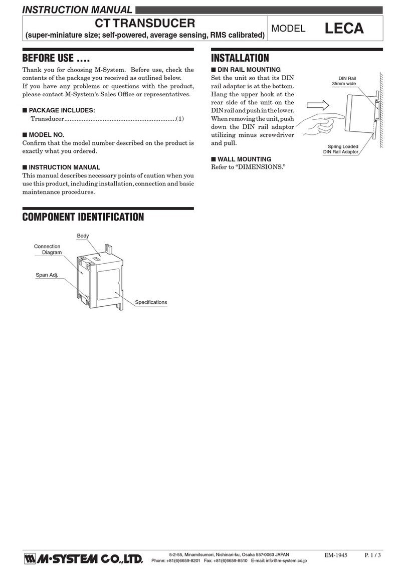
M-system LECA User manual

M-system

M-system LECA User manual
M-system LTWTN User manual

M-system

M-system LTWTN User manual

M-system LTCNE User manual

M-system

M-system LTCNE User manual

M-system 18PA User manual

M-system

M-system 18PA User manual
M-system LT-UNIT Series User manual

M-system

M-system LT-UNIT Series User manual
Popular Transducer manuals by other brands

Siemens ERN 1387 Assemble & disassemble

Siemens

Siemens ERN 1387 Assemble & disassemble

SSET CE-VJ41 -9MSK-0.5 Series instructions

SSET

SSET CE-VJ41 -9MSK-0.5 Series instructions

Lowrance Active Imaging 3-IN-1 installation manual

Lowrance

Lowrance Active Imaging 3-IN-1 installation manual

MKS Baratron 122B instruction manual

MKS

MKS Baratron 122B instruction manual

Lumel P43 user manual

Lumel

Lumel P43 user manual

Sutron ACCUBAR 5600-0120-2 Operation & maintenance manual

Sutron

Sutron ACCUBAR 5600-0120-2 Operation & maintenance manual

Thyracont VSM77PN operating instructions

Thyracont

Thyracont VSM77PN operating instructions

Balluff BTL6-U110-M****-PF-S4 series Condensed guide

Balluff

Balluff BTL6-U110-M****-PF-S4 series Condensed guide

Veris Industries EP3 Series installation guide

Veris Industries

Veris Industries EP3 Series installation guide

MG LTRPN instruction manual

MG

MG LTRPN instruction manual

LEM ITZ 2000-SPR FLEX ULTRASTAB manual

LEM

LEM ITZ 2000-SPR FLEX ULTRASTAB manual

Simrad 50-200 COMBI C -  REV D datasheet

Simrad

Simrad 50-200 COMBI C - REV D datasheet

Agilent Technologies IMG-300 instruction manual

Agilent Technologies

Agilent Technologies IMG-300 instruction manual

TR-Electronic LMP-30-750 PB manual

TR-Electronic

TR-Electronic LMP-30-750 PB manual

S+S Regeltechnik THERMASGARD MWTM-I Operating Instructions, Mounting & Installation

S+S Regeltechnik

S+S Regeltechnik THERMASGARD MWTM-I Operating Instructions, Mounting & Installation

Siedle Novotechnik TP1 CANopen manual

Siedle

Siedle Novotechnik TP1 CANopen manual

MAMAC SYSTEMS PR-274 technical information

MAMAC SYSTEMS

MAMAC SYSTEMS PR-274 technical information

Airmar B60 installation instructions

Airmar

Airmar B60 installation instructions

manuals.online logo
manuals.online logoBrands
  • About & Mission
  • Contact us
  • Privacy Policy
  • Terms and Conditions

Copyright 2025 Manuals.Online. All Rights Reserved.