Table of contents
Symbols used in this manual............................................................................................................................. 1
Package contents.............................................................................................................................................. 2
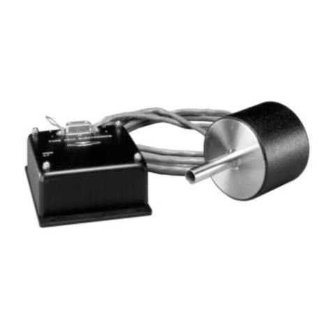
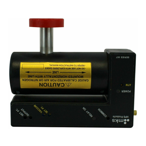
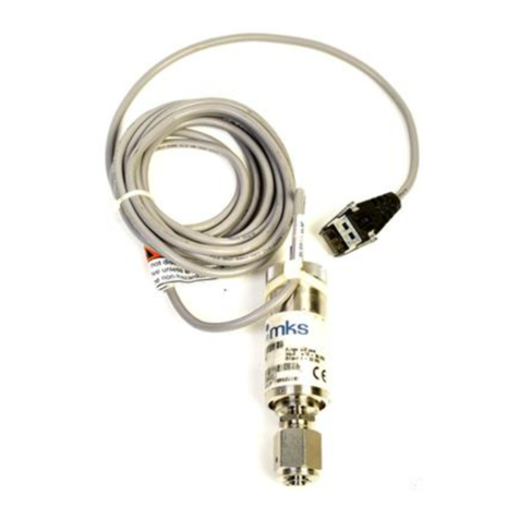
About the 905 MicroPirani™ Sensor Kit............................................................................................................ 3
905 MicroPirani™ Sensor Kit specifications ................................................................................................. 5
MicroPirani™ electronics module pinout....................................................................................................... 5
Electronics module dimensions..................................................................................................................... 6
MicroPirani™ sensor and board dimensions ................................................................................................ 6
About the evaluation board................................................................................................................................ 7
Evaluation board overview............................................................................................................................ 8
Connections.............................................................................................................................................. 8
D-SUB male connector pinout .................................................................................................................. 8
Specifications............................................................................................................................................ 8
Getting started with the 905 MicroPirani™ Sensor Kit...................................................................................... 9
Installing the electronics module............................................................................................................... 9
Connecting the electronics module with the sensor ................................................................................. 9
Choosing communication standard .......................................................................................................... 9
Connecting the communication cable....................................................................................................... 9
Powering up the system.......................................................................................................................... 10
Analog output.......................................................................................................................................... 10
Integrating the 905 MicroPirani™ Sensor Kit .................................................................................................. 11
Choosing a power supply............................................................................................................................ 11
MicroPirani™ electrical connections ........................................................................................................... 12
Flexible flat cable .................................................................................................................................... 12
Regular cable.......................................................................................................................................... 13
Printed circuit board connection.............................................................................................................. 13
Installing the MicroPirani™ sensor.............................................................................................................. 13
Communication ........................................................................................................................................... 14
Example configuration for RS232 and RS485........................................................................................ 14
The signal ‘RS485_ENABLE’.................................................................................................................. 14
Analog Output ............................................................................................................................................. 15
Pressure to voltage table........................................................................................................................ 16
Utilization of remote zero............................................................................................................................. 16
Ground to earth connection......................................................................................................................... 17
Reset switch................................................................................................................................................ 17
Activity LED................................................................................................................................................. 18
Set point outputs ......................................................................................................................................... 18
Integrating the electronics module onto a printed circuit board .................................................................. 18
Updating the firmware................................................................................................................................. 19
Manual procedures for the 905........................................................................................................................ 20
Adjustment for Zero..................................................................................................................................... 20
Venting to Atmosphere................................................................................................................................ 20
Leak Detection ............................................................................................................................................ 20
Operation......................................................................................................................................................... 21
MicroPirani™ Sensor Kit factory defaults table........................................................................................... 21
RS-485 Protocol.......................................................................................................................................... 22
Standard Addresses ............................................................................................................................... 22
Universal Addresses............................................................................................................................... 22
Query and Command Syntax.................................................................................................................. 22
Response Syntax (ACK/NAK)................................................................................................................. 22
RS232 / RS485 Command Set........................................................................................................................ 23
Set Up Commands...................................................................................................................................... 23
Address – AD.......................................................................................................................................... 23
Baud Rate – BR...................................................................................................................................... 23
Factory Default – FD............................................................................................................................... 23
RS Delay – RSD ..................................................................................................................................... 24
Test RS485 – TST .................................................................................................................................. 24
Unit – U................................................................................................................................................... 24
User Tag – UT......................................................................................................................................... 24
Status Commands....................................................................................................................................... 25
Device Type – DT................................................................................................................................... 25
Firmware Version – FV........................................................................................................................... 25
Hardware Version – HV.......................................................................................................................... 25
