ETH-messtehnik GMV2-K User manual

Subject to change without prior notice
OPERATING INSTRUCTIONS
G
GM
MV
V2
2-
-K
K
Microprocessor-Based Power Supply
and Analyzing Unit
for Torque Transducers


ETH-messtechnik gmbh D-74415 Gschwend P.O. 16
Nr.: 162e Operating Instructions GMV2-K revised: 09.05.2019 Rev.: 0
Subject to change without prior notice
3
Content
1GENERAL INFORMATION........................................................................................................................................6
1.1 COMPANY ADDRESS................................................................................................................................................... 6
1.2 DESCRIPTION ............................................................................................................................................................. 6
1.3 FEATURES .................................................................................................................................................................. 6
2STARTUP........................................................................................................................................................................6
2.1 IMPORTANT NOTES .................................................................................................................................................... 6
2.2 FRONT PANEL OF UNIT ............................................................................................................................................... 7
2.3 CONNECTIONS OVERVIEW.......................................................................................................................................... 8
2.4 CONNECTING THE TORQUE TRANSDUCER .................................................................................................................. 9
2.5 SWITCHING ON ........................................................................................................................................................... 9
2.6 SWITCHING OFF ......................................................................................................................................................... 9
3WHAT'S NEW IN SOFTWARE VERSION V5.1 (AFTER V4.1)...........................................................................10
3.1 DYNAMIC REPEAT RATE FOR KEYS........................................................................................................................... 10
3.2 AUTOMATIC CONVERSION OF THE TRANSDUCER FULL SCALE VALUE TO OTHER UNITS ............................................ 10
3.3 SUPPORTING TRANSDUCERS WITH TWO MEASURING RANGES .................................................................................. 10
3.4 IMPROVED SUPPORT FOR A NUMBER OF INPUTS ....................................................................................................... 10
3.5 UNIVERSAL INPUT RANGE FOR THE ACTIVE AND PASSIVE INPUT .............................................................................. 10
3.6 ADJUSTABLE OVERLOAD RANGE.............................................................................................................................. 11
3.7 AUTOMATICALLY TRACKING ZERO-POINT DRIFT ..................................................................................................... 11
3.8 PULSE-TYPE SCREWDRIVER MODE ........................................................................................................................... 11
3.9 STREAMLINING PARAMETER SET ENTRY .................................................................................................................. 11
3.9.1 Defaults...........................................................................................................................................................11
3.9.2 Hiding unused functions .................................................................................................................................11
3.9.3 Correction factor ............................................................................................................................................12
3.9.4 Filter for peak measuring ...............................................................................................................................12
3.10 DELETING MEASURED VALUES ................................................................................................................................ 12
3.11 DETECTING NEW TRANSDUCERS AND NEW MEASURING RANGES ............................................................................. 12
3.12 POWER-SAVING FUNCTION (STANDBY) .................................................................................................................... 12
3.13 CANCEL SERIAL TRANSMISSION ............................................................................................................................... 12
3.14 CONTINUOUS OUTPUT WITH A MINIMUM 0.5 SECOND INTERVAL PERIOD ................................................................. 12
3.15 ANALOG OUTPUT ..................................................................................................................................................... 12
3.16 BATTERY PROTECTION ............................................................................................................................................ 13
4MENU STRUCTURE...................................................................................................................................................13
4.1 INTRODUCTION ........................................................................................................................................................ 13
4.2 DIRECT FUNCTION KEYS .......................................................................................................................................... 13
4.3 MEASURE MENU ...................................................................................................................................................... 14
4.4 MENU: DELETE MEASURED VALUE .......................................................................................................................... 14
4.5 MENU: OUTPUT ....................................................................................................................................................... 14
4.6 PARAMETER MENU .................................................................................................................................................. 14
4.6.1 Transducer......................................................................................................................................................14
4.6.2 Limits ..............................................................................................................................................................15
4.6.3 Settings............................................................................................................................................................16
4.6.4 Parameter set..................................................................................................................................................16
5SETTINGS ....................................................................................................................................................................16
5.1 FUNCTIONS .............................................................................................................................................................. 16
5.2 PASSWORD .............................................................................................................................................................. 16
5.3 INITIAL SETTINGS..................................................................................................................................................... 16
5.4 DEFAULTS ............................................................................................................................................................... 16
6INITIAL SETTINGS....................................................................................................................................................17
6.1 LANGUAGE .............................................................................................................................................................. 17
6.2 TIME OF DAY AND DATE .......................................................................................................................................... 17
6.3 PRINTER (SERIAL INTERFACE) ................................................................................................................................. 17
6.4 USB2.0-INTERFACE ................................................................................................................................................ 17

ETH-messtechnik gmbh D-74415 Gschwend P.O. 16
Nr.: 162e Operating Instructions GMV2-K revised: 09.05.2019 Rev.: 0
Subject to change without prior notice
4
6.5 STANDBY (POWER-SAVING FUNCTION) .................................................................................................................... 17
6.6 DISPLAY ILLUMINATION .......................................................................................................................................... 18
6.7 CONTRAST OF DISPLAY ........................................................................................................................................... 18
7MEASURING MODES ...............................................................................................................................................18
7.1 TRACKING MEASUREMENTS .................................................................................................................................... 18
7.2 FILTER ..................................................................................................................................................................... 18
7.3 OUTPUTTING MEASURED VALUES CONTINUOUSLY .................................................................................................. 18
7.4 SPEED MEASUREMENTS ........................................................................................................................................... 19
7.5 POWER MEASUREMENT ........................................................................................................................................... 19
7.6 PEAK MEASURING ................................................................................................................................................... 19
7.7 TORQUE WRENCH MEASUREMENTS ......................................................................................................................... 19
8THE ENTRY EDITOR................................................................................................................................................20
8.1 INTRODUCTION........................................................................................................................................................ 20
8.2 SELECT SETTINGS .................................................................................................................................................... 20
8.3 ENTERING NUMBERS ............................................................................................................................................... 20
8.4 TRANSDUCER FULL SCALE VALUE ........................................................................................................................... 20
8.5 ALPHANUMERIC TEXTS ........................................................................................................................................... 21
9THE PARAMETER SET ............................................................................................................................................21
9.1 INTRODUCTION........................................................................................................................................................ 21
9.2 DESCRIPTION TEXT FOR PARAMETER SETS .............................................................................................................. 21
9.3 PARAMETER SET "0" ................................................................................................................................................ 21
9.4 PARAMETER SET DISPLAY ....................................................................................................................................... 22
9.5 PRINTOUT OF THE PARAMETER SET ........................................................................................................................ 22
9.6 SELECTION .............................................................................................................................................................. 23
9.7 CREATE NEW ........................................................................................................................................................... 23
9.8 EDITING .................................................................................................................................................................. 23
9.9 ERASE ..................................................................................................................................................................... 26
10 SCREWING TECHNOLOGY................................................................................................................................27
10.1 TIME-BASED SEQUENCE DIAGRAM ......................................................................................................................... 27
10.2 TIMING .................................................................................................................................................................... 27
10.3 ANGLE .................................................................................................................................................................... 28
11 STORING MEASURED VALUES.........................................................................................................................28
11.1 THE MEASURED-VALUE STORAGE ........................................................................................................................... 28
11.2 THE DATA RECORD .................................................................................................................................................. 28
11.3 MEMORY SETTINGS................................................................................................................................................. 28
11.4 DISPLAYING THE STORED MEASURED VALUES ........................................................................................................ 29
11.5 DELETE MEASURED VALUES .................................................................................................................................... 29
12 PRINTING OUT THE STORED MEASURED VALUES...................................................................................30
13 OPTIONAL FUNCTIONS ......................................................................................................................................31
13.1 BATTERY OPERATION .............................................................................................................................................. 31
13.2 PASSIVE INPUT ........................................................................................................................................................ 31
13.3 DIGITAL INPUT ........................................................................................................................................................ 31
13.4 MEASURED-VALUE TRANSMISSION GMV2-K PC ............................................................................................... 31
13.4.1 FUNCTION ........................................................................................................................................................... 31
13.4.2 MENU BAR .......................................................................................................................................................... 31
13.4.3 DATA TRANSMISSION .......................................................................................................................................... 31
13.4.4 MEASURED-VALUE TABLE .................................................................................................................................. 32
13.4.5 STATISTICAL ANALYSIS ....................................................................................................................................... 32
13.4.6 MEASURED-VALUE DIAGRAM .............................................................................................................................. 32
13.4.7 TORQUE WRENCH DOCUMENT ............................................................................................................................. 32
13.4.8 GENERAL INFORMATION ..................................................................................................................................... 33
13.5 INPUTS / OUTPUTS ................................................................................................................................................... 33
13.6 SHUTDOWN FOR ELECTRIC SCREWDRIVERS ............................................................................................................. 33
13.7 SHUTDOWN OF HYDRAULIC UNIT ............................................................................................................................ 33
13.8 OK OUTPUT ............................................................................................................................................................. 33
13.9 NOK OUTPUT .......................................................................................................................................................... 33
13.10 ANALOG OUTPUT ................................................................................................................................................ 33

ETH-messtechnik gmbh D-74415 Gschwend P.O. 16
Nr.: 162e Operating Instructions GMV2-K revised: 09.05.2019 Rev.: 0
Subject to change without prior notice
5
13.11 EXTERNAL CONTROL ........................................................................................................................................... 34
13.11.1 Zeroadjust...................................................................................................................................................34
13.11.2 Storing / Printing / Erasing.........................................................................................................................34
13.12 MEASURED-VALUE PRINTOUT TO THE DIGIMATIC DP-1 HS ................................................................................ 34
13.12.1 Introduction ................................................................................................................................................34
13.12.2 Connection and preparation.......................................................................................................................34
13.12.3 Transmission of limits.................................................................................................................................35
13.12.4 Printing out the measured values................................................................................................................35
14 ERROR MESSAGES ...............................................................................................................................................35
14.1 GENERAL ................................................................................................................................................................. 35
14.2 FAULTS AND THEIR CAUSES ..................................................................................................................................... 36
15 PIN ASSIGNMENTS ...............................................................................................................................................37
11 DISPOSAL CONSIDERATIONS...........................................................................................................................38
12 OVERVIEW OF THE GMV2-K V5.1 MENU STRUCTURE .............................................................................39

ETH-messtechnik gmbh D-74415 Gschwend P.O. 16
Nr.: 162e Operating Instructions GMV2-K revised: 09.05.2019 Rev.: 0
Subject to change without prior notice
6
1 General information
1.1 Company address
ETH Messtechnik GmbH, Hagstr. 10, 74417 Gschwend, Germany
1.2 Description
GMV2-K is a microprocessor-based measuring, control and analyzing unit for the most common screwing and laboratory
applications. Due to its compact design and optional battery operation, the unit is very suited for portable use. Measured
values can be stored and printed out with date and time of day. The power-operated screwdriver can be automatically
switched off with separate power circuitry.
1.3 Features
•Menu-assisted operation and setting
•Recording torque, angle of rotation, speed and power
•For torque transducers from 1 Ncm to 100 kNm full scale value
•Shut off according to torque and/or angle of rotation (optional)
•1000 measured-value storage
•50 parameter set storage
•Mains operation (100V – 240V) or optional integrated charger, 8-hour battery operation.
•RS-232 port for printer
•Measured-data transmission to PC
•EMC sealed housing
2 Startup
2.1 Important notes
If the unit is opened or dismounted within the warranty period the warranty will be rendered null and void.
The unit should only be opened by qualified staff.
Only cables designed for use with the unit may be connected to it. Damage caused by connecting incorrect cables are not
covered by the warranty.
In battery operation, operation of the electric screwdriver is not possible!
The unit is not grounded during battery operation. Should current-carrying equipment be connected to the unit they must be
grounded according to technical regulations.
The full scale value displayed on the screen must always correspond with the actual transducer being used.
Where there is a risk of injury to persons and damage to equipment, the user must take appropriate safety measures (for
example, use covers, overload protection devices) (relevant accident prevention regulations should be observed!).
Due to the use of surge arresters (Varistors) an Insulation measurement according VDE 701/702 is not possible.
Please use the substitute leakage current measurement method according VDE 701/702.
The unit is not approved for service in hazardous areas.
ETH-messtechnik gmbh D-74415 Gschwend P.O. 16
Nr.: 162e Operating Instructions GMV2-K revised: 09.05.2019 Rev.: 0
Subject to change without prior notice
7
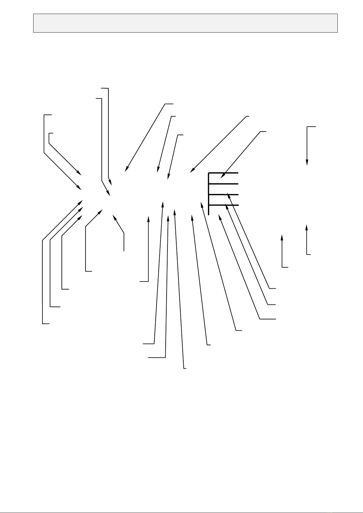
2.2 Front panel of unit
E1 < CW peak A SR : 995
↓8,10
Nm
P: 1 ST : 5 DR : 1 10 Nm
Zeroadj
Test
Menu
NIO ↓12 Grad
Error:
Charg
90%
Op no:
<Engine block-K> ID no 1234-03
ON/
OFF
Return
The four
menu keys
Key without
function
Transducer full
Torque
Angle of rotation or speed
Parameter set
number
Field for
error messages
Data
record
Memory number
Mode
direct function
Zeroadj /Clear
direct function
Transducer Test
Menu tree selection
Remaining store
(number of free memory
Assessment of angle
Assessment of torque
Overall assessment
Peak status
Password level
Correction factor or filter
time
Parameter set
text
Operator no.
ID text
for data records
Automatic tracking of zero-point drift

ETH-messtechnik gmbh D-74415 Gschwend P.O. 16
Nr.: 162e Operating Instructions GMV2-K revised: 09.05.2019 Rev.: 0
Subject to change without prior notice
8
2.3 Connections overview

ETH-messtechnik gmbh D-74415 Gschwend P.O. 16
Nr.: 162e Operating Instructions GMV2-K revised: 09.05.2019 Rev.: 0
Subject to change without prior notice
9
2.4 Connecting the torque transducer
Suitable connection cables are available for different types of torque transducers!
This standard GMV2-K unit has been designed for use with active transducers with a ± 1.25V to ± 10V signal. A
±0.5mV/V to ±4mV/V passive input and a digital input are available as an option. Please use the appropriate cable only
which can be obtained from ETH.
2.5 Switching on
You can switch the unit on with the button when you have checked that the cable has been correctly connected.
After a short self-test all settings valid before the unit was switched off are reloaded. The transducer is now zeroed. The
unit is then ready. If the error message "Charge!" appears now, please connect the power cable. You can now power the
unit from the mains or switch it off and let it charge for approximately five hours.
If you keep the key pressed while switching on the device, time of day, software version and the optional functions will be
displayed. The following abbreviations appear:
•V x.xx Software version
“-”
•ax Active input with adjustable input range
•px Passive input with adjustable input range
•d Digital input
“-”
•W Angle measurement
•T PC transfer
•E I/Os
•D Output for Digimatic printer
Notes:
−When the unit is being switched on the outputs are operated for a short period. The manual switch for the power-
operated screwdriver should therefore be switched off during power-up.
−Check before the first measurement that the initial settings for the unit (see Sec. 6) meet your requirements.
−If the battery is not charged fifteen minutes after the first charge message, the unit switches itself off.
When the calibration period for the GMV2-K has elapsed, the error message
“Error: Calibration date” appears when the device is switched on. In this case, please send the device to ETH.
2.6 Switching off
You can switch off the device with the button. If the power-saving function (standby) is enabled, the device switches
itself off if it unused for a set period. If, due to a fault, you cannot operate or switch off the unit, you can remove the fuse
from the rear (data may however be lost in this case).

ETH-messtechnik gmbh D-74415 Gschwend P.O. 16
Nr.: 162e Operating Instructions GMV2-K revised: 09.05.2019 Rev.: 0
Subject to change without prior notice
10
3 What's new in software version V5.1 (after V4.1)
3.1 Dynamic repeat rate for keys
The keys (+, -, choose, etc.) now have a repeat function when pressed for longer periods.
The repeat rate increases continually.
3.2 Automatic conversion of the transducer full scale value to other units
When a transducer with integral chip is connected to the device, a unit that is different to the transducer unit may be
selected in the parameter set. The transducer full scale value is automatically converted to the selected unit. Only the
available units can now be used!
Example:
•Transducer with 10 Nm, selected unit “InLb” displayed full scale value: 88.51 Inlb
•Transducer wit 10 Nm, selected unit “Ncm” displayed full scale value: 1000 Ncm
Note:
•If, when programming a parameter set, a particular unit is not available, disconnect the transducer and then choose the
wanted unit.
3.3 Supporting transducers with two measuring ranges (option on request)
Transducers with two measuring ranges can now be connected to the active socket.
The small measuring range appears in the menu as “akt2rng, standard_range”.
The large measuring range appears in the menu as “akt2rng, high_range”.
Note:
•This is an optional function and is not available in all devices
•Select the “Standard_range” option for transducers with only one measuring range!
3.4 Improved support for a number of inputs
When the GMV2-K supports inputs for a number of transducer models, each of the available inputs can be selected as
required. The GMV2-K socket designation, the transducer model and, if applicable, the measuring range (stndrt / large)
will be displayed.
In addition, this information is also output when the parameter set is displayed or printed out.
Note:
•This is an optional function and is not available in all devices
3.5 Universal input range for the active and passive input
Menu path:
•“Menu -> Param -> ParSet -> Change -> Edit”
•“Menu -> Param -> Transducer -> “Model” or “Sig./Ua”
The inputs can be adjusted easily now to the output signal from most sensors. They can be programmed separately for each
parameter set. If a default value is available, it will be used without the system asking for confirmation. The correct value
can be entered for every parameter set with the setting “Enter” for Ua. This is how the calibration value is entered for
passive transducers.
Input range:
Active input: ±1.25V to ±10V in steps of 1mV, or 5V / 10V
Passive input: ±0.5mV/V to ±4mV/V in steps of 1µV/V, or 1mV/V / 2mV/V / 4mV/V
Note:
This is an optional feature and therefore not available in all devices

ETH-messtechnik gmbh D-74415 Gschwend P.O. 16
Nr.: 162e Operating Instructions GMV2-K revised: 09.05.2019 Rev.: 0
Subject to change without prior notice
11
3.6 Adjustable overload range
Menu path:
•“Menu -> Param -> Param set -> Change -> Edit”
•“Menu -> Measure -> Overload
The measuring range can now be much larger than the nominal signal of the transducer. The overload range can be
programmed separately for each parameter set from 0% to 100% of the transducer end value – however, the resolution of
the displayed measurement is reduced in proportion to the selected overload range. Different values can be programmed by
selecting “Enter” in the defaults under overload range.
(Menu path: “Menu -> Param -> Setting -> Defaults -> Overload”).
Caution
•If the mechanical overload capability of the torque transducer is exceeded for even a short period, this will
immediately destroy the transducer!
3.7 Automatically tracking zero-point drift
The zero voltage on torque sensors varies slightly as a function of temperature: the zero-point drifts when the device is
switched on until the sensor reaches its operating temperature. In the zero-load condition, the system detects and tracks this
drift and compensates for it accordingly. The device continues to take correct measurements. When the tracking function
for zero-point drift is active, an “A” (Automatic) appears at the bottom of the screen.
3.8 Pulse-type screwdriver mode
This function is very similar to the peak measuring function: additionally, a correction factor is available in this mode, but
angle measurements cannot be taken.
3.9 Streamlining parameter set entry
3.9.1 Defaults
Menu path: “Menu -> Param -> Setting -> Defaults”
In “Defaults” either a fixed numerical value or “Enter” may be selected.
The desired value may be entered when programming a parameter set and when “Enter” is set.
When a fixed numerical value is the default setting, it is automatically loaded without confirmation from the user
when a parameter set is programmed. This saves multiple data entries.
A default setting is available for each of the following:
- input sensitivity of the active and passive input
- overload range
- automatic tracking of zero-point drift
Examples:
•If you always use thread adapter transducers (DRFS..., DRFN...), select active - 5V
•If you always use laboratory transducers (DRL), select active - 10V
•Select passive, Enter for passive transducers
Note:
•Changes to the default setting do not immediately impact the current parameter set!
The default setting is not loaded until a parameter set is processed or programmed.
•Parameter sets that have already been programmed are not changed when defaults are changed.
3.9.2 Hiding unused functions
Menu path: “Menu -> Param -> Setting -> Function”
Functions that are seldom used can be hidden, so that they are disabled (without user confirmation) when a parameter set is
programmed. The process of entering the parameter set is thus shortened.
The functions are always available in the direct parameter entry menu.: “Menu -> Measure ... / Parameter..”.

ETH-messtechnik gmbh D-74415 Gschwend P.O. 16
Nr.: 162e Operating Instructions GMV2-K revised: 09.05.2019 Rev.: 0
Subject to change without prior notice
12
Example:
•The “Parameter set text, data record ID and operator number” menu can be hidden for all operating modes (“More”).
•Angle, speed and power measurement are disabled during tracking measurements.
Note:
•Changing the functions does not immediately impact the currently available parameter sets!
3.9.3 Correction factor
A correction factor may only be entered in the (new) operating mode “impulse wrench”
3.9.4 Filter for peak measuring
This function is no longer available in version V5.2!
3.10 Deleting measured values
Menu path: Menu -> MVclear...
The operator can now choose whether he wants to delete all measured values, the measured values in a parameter set, or
only single data records (see sec. 11.5, page 29).
3.11 Detecting new transducers and new measuring ranges
When ETH transducers that are equipped with a memory chip are used, the GMV2-K detects the removal and insertion of
the transducer, and when the measuring range is changed. The device is subsequently zeroed and the system checks that the
settings in the parameter set match the transducer settings.
3.12 Power-saving function (standby)
Menu path: Menu -> Param -> Setting -> Initial setting -> Standby
To save power, the LCD illumination and the GMV2-K power themselves off after set time periods, which can be adjusted.
This function may also be disabled.
Adjustable delay times for switching off the LCD illumination are: 1 min – 1 h. Adjustable delay times for switching off
the device are: 1 min – 3 h.
Note:
•These delay times are reset when measured values are saved or output.
•The standby function is disabled when the output is continuous.
3.13 Cancel serial transmission
Serial transmission can be canceled with the OFF key.
3.14 Continuous output with a minimum 0.5 second interval period
The minimum cycle time has been increased to 0.5 seconds due to the enhanced functionality of the GMV2-K.
3.15 Analog output
The optional analog output is now zeroed with the Zeroadjust key. Additionally, the automatic tracking of zero-point drift
is enabled.
Note:
•The output signal is scaled to ±5V independently of the input signal (passive, active & digital).
•The overload range must be set to 7% (standard).

ETH-messtechnik gmbh D-74415 Gschwend P.O. 16
Nr.: 162e Operating Instructions GMV2-K revised: 09.05.2019 Rev.: 0
Subject to change without prior notice
13
3.16 Battery protection
To prevent the battery from totally discharging and thus protect it from damage, the device powers itself off when the
battery is low.
4 Menu structure
4.1 Introduction
The GMV2-K offers extensive measuring, control and adjusting features.
A hierarchical menu system is available to allow simple, self-explanatory operation.
A menu offers a list of selection options similar to a menu in a restaurant.
Each selection in turn offers further selections (and so on). A structure is generated that is similar to the branching of a tree.
The menu structure is shown in page 39. The actual functions are situated at the end of the "branches".
When the unit is first switched on it is in normal operating mode, that is, in level 0 in the menu structure. The GMV2-K is
only ready here. In addition to status information, torque, and if necessary angle and OK /NOK assessment (arrows) are
displayed in the first and last lines (see Sec. 2.2, page 7) on the screen.
Use the "Menu" key to enter the menu tree. You may navigate to the right in the tree, that is, to a higher level with the four
menu keys on the right beside the screen.
Use the return key to move back again to the left or to the next lower level.
The menu path is described as "X-> Y-> Z", which means:
When you press menu key ("X"), you reach the next menu. When you press the "Y" key here you reach a menu, where you
can select "Z".
4.2 Direct function keys
In normal operation (level 0) there are three keys with which a function is immediately executed when pressed. Some direct
function keys are assigned multiple functions. The assigned function depends on the settings selected. When no function is
assigned to the key there is no inscription and the key is disabled.
Note: The password for the first level also blocks the direct function keys.
•Store - Output / Start - Stop:
1.) Store: The value displayed on the screen is stored in the measured-value memory every time the key is pressed
(manual save).
2.) Output: The value displayed on the screen is printed out through the RS 232 serial port every time the key is
pressed (one-off manual printout).
3.) Start - Stop: Continuous measured-value output can be started (“contin” appears in the bottom line) or stopped.
•Clear / Zeroadjust:
1.) Clear the measured peak value. Torque and angle of rotation are reset to "0", Counters are reset and restarted. The
unit starts the measuring process from the beginning. The measurement is not stored! Press the Store key beforehand
for manual saving!
2.) Zeroadjust transducer and display. The offset voltage for the transducer is compensated so that, with no loading, the
value "0" appears on the screen. Zeroadjust should be repeated often as every transducer drifts with temperature. The
transducer must be completely unloaded during Zeroadjust!
Notes:
−If the offset voltage is greater than the adjusting range of the unit, an error message is output to the screen, and the
procedure must be repeated. Otherwise, accurate measurements cannot be taken!
This fault may be caused by loading the transducer during Zeroadjust, or it indicates that the transducer (overloading) or
the connection cable are defective.
−The transducer is automatically zeroed when the unit is switched on and when you return from the menu level.

ETH-messtechnik gmbh D-74415 Gschwend P.O. 16
Nr.: 162e Operating Instructions GMV2-K revised: 09.05.2019 Rev.: 0
Subject to change without prior notice
14
•Test:
"Test" serves to test the transducer. It outputs its maximum signal, the full scale value for the transducer is displayed on
the screen. However, this test cannot be performed in the peak measuring mode with counter-clockwise rotation! The
“On/Off” button is also available.
The "Return" key serves to return to the previous a level in the menu. Typically, to return to normal operation this key
must be pressed a number of times. If you are in normal operation when you press the "Return" key, you will return to
password level 0.
4.3 Measure menu
For direct and fast changeover of the peak, track, torque wrench or speed measurement modes without having to program a
parameter set. Parameter set "0" is selected automatically! Parameter set "0" contains the settings for the current parameter
set.
Notes:
−This menu is only suited for determining screwing parameters. Measured values and parameters cannot be saved!
Finally, you should create a new parameter set with these settings. See sec. 9.7, page 23
−A power-operated screwdriver cannot be switched off during tracking measurements!
−For torque wrench measurements the yielding moment should be at least 2% of the transducer full scale value.
4.4 Menu: Delete measured value
Menu path: Menu-> MVclear ...
See also sec. 11.5, page 29
4.5 Menu: Output
Measured values and parameter sets can be either displayed on the screen (see secs 11.4 and 9.4) or printed out through the
serial interface (see secs 12 and 9.5). Alternatively they can be uploaded to a computer .
In “Menu -> Output-> Display-> Light” the LCD display illumination can be switched on/off and in “Menu -> Output->
Display-> Contrast” the display contrast can be set manually.
4.6 Parameter menu
4.6.1 Transducer
Menu path: Menu-> Param-> Transducer
This menu allows the values for the torque transducer to be set directly in the test phase (parameter set no. 0). It subdivides
into "Full scale value", "Angle" and "Type" or “Sig./Ua” and “Zeroadjust”.
•The full scale value is set with the Entry editor (see Sec. 8.4).
•The "Angle" menu can be used to define whether the transducer used allows an angle measurement.
Angle decoders with 360 pulses per revolution are supported in this version.
The limits must be entered to display the angle on the screen! (Menu-> Parameter-> Limit-> Angle)
Note:
Angle measurement is only available in the software version with suffix "W".
•Different inputs for different transducer types can be selected in the "Type" / “Sig./Ua” menu depending on the
configuration level of the unit. GMV2-K is equipped with an active input as standard. A passive input and a digital
input are available as an option. If the type is selected, the transducer output signal can be entered in volts or mV/V.
•Automatic tracking of zero-point drift can be enabled/disabled in the “zero” menu..

ETH-messtechnik gmbh D-74415 Gschwend P.O. 16
Nr.: 162e Operating Instructions GMV2-K revised: 09.05.2019 Rev.: 0
Subject to change without prior notice
15
4.6.2 Limits
Menu path: Menu-> Param-> Limits
Limits can be set directly in this menu in the test phase (parameter set no. 0). It subdivides into "Torque", "Angle" and
"Timing".
Torque limits:
•All limits are also entered as unsigned numbers for counter-clockwise rotation.
•The limit evaluation display (arrow) uses the angle value (unsigned).
•"Limit max" and "Limit min" define the maximum and minimum allowed torque (OK window).
•"Shut off" determines the torque at which the power-operated screwdriver is switched off. However the "Inputs/outputs"
option and external power circuitry are required for this function and it is only enabled for peak measuring.
"Trigger" defines the torque at which angle counting begins. This is normally the joining torque.
Operation:
The torque limits are not entered here with the entry editor!
The current value appears on the screen. You can increment or decrement this value with the "+" and "-" keys. A brief
keystroke changes the last digit by a minimum amount. The longer you hold the key pressed, the quicker the display runs.
You should therefore release the key briefly before the desired number to allow you to make the fine adjustment more
slowly.
The "no" key disables the limit value.
Confirm the entry with "OK", because the return key aborts the changes!
Notes:
−All limits are also entered for counter-clockwise rotation as unsigned numbers.
−Torques are entered here without a plausibility check. This means that the minimum value can be set greater than the
peak. The user is responsible for the correctness of the entries here.
−All torques must exceed 5% of the full scale value so as to be detected! If you enter "0" as a trigger, the torque must
exceed 5% of the full scale value for peak measuring, so that angle counting can begin.
Angle limits:
In contrast to the torque limits, angle limits are entered with the Entry editor (see Sec. 8.3). This means that the angle entry
can only be terminated with "OK". The previous menu level is then automatically selected. If the return key is pressed
during entry the previous value is reloaded. There is also no plausibility check here. However if a transducer without angle
is selected, the angle menu is disabled and an error message is output.
You can activate the angle functions with "Menu-> Parameter-> Transducer-> Angle-> on".
•All limits are also entered for counter-clockwise rotation as unsigned numbers.
•The limit evaluation display (arrow) uses the angle value (unsigned).
•"Limit max" and "Limit min" define the allowed maximum and minimum angle of rotation (OK window). Counting
begins when the trigger torque is exceeded. You can define this with the torque limits.
•"Shut off" defines the angle of rotation at which the power-operated screwdriver is switched off. However the
"Inputs/outputs" option and external power circuitry are required for this purpose.
Note:
The "Angle limits" menu is only available in the variant with suffix "W".
Timing:
The times are also entered with the Entry editor (see Sec. 8.3)
Undesirable torque peaks that can occur at the beginning of screwing are suppressed during the "Suppression phase". This
occurs when the power-operated screwdriver is being mounted, and especially with self-tapping screws.
The value "0" disables the timing.
The "After Time" defines how long the peak measuring and angle counting remain active after the power-operated
screwdriver has been switched off. The value “0” disables the time period so that the GMV2-K is always ready. It should
not be too small. Otherwise, the power-operated screwdriver with its centrifugal mass runs on when the measurement has
been stopped. In which case too small a value would be displayed. This time period depends on the screwing application
and must be determined for each individual case. If possible, therefore, you should use the default setting “0” !
If it has to be changed, select a long period!

ETH-messtechnik gmbh D-74415 Gschwend P.O. 16
Nr.: 162e Operating Instructions GMV2-K revised: 09.05.2019 Rev.: 0
Subject to change without prior notice
16
4.6.3 Settings
The GMV2-K settings are described in detail in secs 5 and 6.
4.6.4 Parameter set
This is the most important menu. A parameter set must be created (programmed) before measurements can be taken or
screws can be screwed. This topic is so comprehensive that it is dealt with in a separate section. See sec. 9.
5 Settings
5.1 Functions
Menu path: “Menu -> Param -> Setting -> Function”
You can enable/disable different functions.
5.2 Password
Menu path: “Menu -> Param -> Setting -> Password”
You can program a password (maximum 4-digit number) for each of the three levels as a
protection for the device settings against unauthorized change. First, you need to enable
level 3. You can then select the level, for which you want to change the password. The
system prompts you to enter the password. As soon as you enter a number greater than
zero, password protection is enabled and you will be prompted to note down this number.
The password protection in the level is disabled if you enter a zero as password. The
system will then also display the message ”Protection disabled”. The sections in the levels
of the menu structure (sec. 12, page 39) are highlighted in color. The enabled level is
shown on the bottom left of the screen.
If the password is programmed in the first level, all keys, except the On/Off key and the password prompt are disabled. To
return to level 0, press the “Return” key again in measuring mode!
You can jump from level zero to level 3 by entering the password for level 3 (see diagram).
Additionally only a certain level may be protected with one
password, which means that different levels of password
protection can be assigned to different user groups.
Example:
If only the password for the third level is programmed (left
diagram), everyone has access to the functions on levels 1 and
2 without a password. Since there is no password available for
the first and second levels, they merge with the measuring
mode. A password is needed for the third level.
Note:
•You should assign a password, at least, to the third level to prevent unauthorized persons from setting
passwords!
•Should you forget your passwords, we can provide you with instructions on how to delete all passwords.
5.3 Initial settings
See sec. 6
5.4 Defaults
See sec.3.9.1, page 11.
Measurement
Level 1
Level 2
Level 3
Password
for
level 1
Password
for
level 3
Password
for
level 2
Passwords set for level 1 to 3
(Level 0)
Measurement
Level 1
Level 2
Level 3
Password set for level 3 only
(Level 0)
Measurement
Level 1
Level 2
Level 3
Password set for level 1 only
(level 0)

ETH-messtechnik gmbh D-74415 Gschwend P.O. 16
Nr.: 162e Operating Instructions GMV2-K revised: 09.05.2019 Rev.: 0
Subject to change without prior notice
17
6 Initial settings
6.1 Language
Menu path:
Menu-> Parameter-> Program-> Initial setting-> Language
The unit is fully multilingual. If the language is changed, screen texts, key labels and date format are adapted accordingly.
The setting becomes effective when the language key is pressed (Caution!)
German, English, French and Italian have been realized for this software version.
Note:
Other languages can be realized at customer request.
6.2 Time of day and Date
Menu path:
Menu-> Parameter-> Setting-> Initial Setting -> Clock
The actual time of day is displayed at the bottom of the screen. A flashing underline (cursor) indicates what can be
changed. You can change the compete numbers only with the “+” und “-” keys, i.e. you cannot change the units and tens
separately. The longer you keep the keys pressed, the quicker numbers will change (dynamic).
Use the “<==” key to move between minute, hour, day, month and year. Don't forget to press the OK key to save the time
of day! Press the return key to cancel the setting.
Notes:
−Date and time of day are briefly flashed on the screen when the unit is switched on – which allows you to check
them.
6.3 Printer (Serial interface)
Menu path:
Menu-> Parameter-> Setting -> Initial setting -> Printer
Procedure:
First select the desired printer. For "Standard" and “==> PC” the system prompts you for the baud rate. No baud rate setting
is required for DP-1 HS.
1.) Selecting the printer:
•"Standard" key for standard printer, (PC transmission with the program “Hyperterminal”)
•“===> PC“ key for measured-value transmission in an EXCEL® file (optional)
The keystroke makes the selection immediately effective and item 2. is selected).
2.) Setting the baud rate:
Default values 1200 baud to 19200 can be selected in succession with "+" and "-" keys.
The OK key accepts the selected setting.
The return key cancels the change and jumps to the "Initial setting" menu.
Notes:
•Factory default: baud rate 4800 Bd (suitable for printers supplied by us!), standard printer.
•Transmission format: 8 data bits, no parity, 1 stop bit, XON-XOFF, text transmission
•See Sec. 15. for pin assignment
Other formats are available at customer request.
6.4 USB2.0-Interface
To use the USB2.0 interface, first install the supplied driver software! Only then may the USB port be used.
6.5 Standby (power-saving function)
See sec. 3.12., page 12.

ETH-messtechnik gmbh D-74415 Gschwend P.O. 16
Nr.: 162e Operating Instructions GMV2-K revised: 09.05.2019 Rev.: 0
Subject to change without prior notice
18
6.6 Display illumination
Menu path:
Menu-> Output-> Display-> Light
LCD lighting is turned on and off by pressing the "Light" key.
Note:
•In standby mode, display illumination is switched off after a set period if no keys are pressed (see Sec. 3.13). Press a
key (Test, Return, ...) to switch illumination back on again.
6.7 Contrast of display
Menu path:
Menu-> Output-> Display-> Contrast
Use the“+” and “-” keys to set the contrast. If the contrast is too high, the background will be dark; if the contrast is too
low, the figures will be pale.
Note:
•The contrast should only be changed for extreme ambient temperatures
7 Measuring modes
7.1 Tracking measurements
Appropriate for continuous display of static or very slowly changing torques and angles.
To read the values, the tracking measurements must be slow. The display follows fast changes in torque with a delay,
which depends on the filter setting, see the next section.
Notes:
•Speed measurement and power measurement can be activated here if angle measurement has been de-activated.
•The switch-off function is not available here!
•An adjustable filter can also be programmed (0.1 to 10 s).
•If switched on, the optional angle counting function is permanently enabled. It is reset when the transducer is
zeroadjusted.
7.2 Filter
Menu path: “Menu -> Param -> Param set -> New -> Program”
In the laboratory, very often the torque and the speed do not remain constant during a revolution – this makes it difficult to
read the display. This filter is based on the moving average and it can filter out these fluctuations. The range of the time
period over which the measured values are averaged can be set between 0.1 s and 10 s. This time period applies to the
torque, the speed and thus to the power measurement. Filtering is optimized by selecting the filter time according to the
following formula and by making it as big as possible:
Filter time[s] = n * 60 / speed[min-1]; n = 1, 2, ....
Example:
For a speed of 30 rev/min, select a time between 2.0 s and 10.0 s.
Note:
Please keep in mind that double the filter time must elapse before the final value appears on the display.
7.3 Outputting measured values continuously
Menu path: “Menu -> Param -> Param set -> New -> Program”
Tracking measurements can be continuously printed out or saved. The allowed interval time ranges from 0.5 s to 900 s
(15 min). Typically, the maximum output rate is determined by the printer speed.

ETH-messtechnik gmbh D-74415 Gschwend P.O. 16
Nr.: 162e Operating Instructions GMV2-K revised: 09.05.2019 Rev.: 0
Subject to change without prior notice
19
7.4 Speed measurements
This measuring mode is a variation of the tracking measurement and is not a separate operating mode!
It is only a function in its own right in "Menu-> Measure-> Track-> Speed" (parameter set no. 0). During parameter set
programming, speed measurement is activated by selecting tracking measurement without angle measurement and finally
starting speed measurement with "yes". You can select between 60 and 360 pulses per revolution: this allows you to record
the speed for torque transducers with angle measurement.
Notes:
•The speed is determined for the duration of a second.
•Maximum speed: 30, 000 -1
•Accuracy: ±1 digit;
7.5 Power measurement
This mode is an extra function under tracking measurements and is not an operating mode in its own right!
It is only a separate function under “Menu-> Measure-> Track-> Power” (parameter set 0).
Power measurement can be started when programming the parameter set after speed measurement has been enabled.
Selecting the format determines the maximum power that can be displayed. If the scale range is exceeded, “-----” is
displayed.
Note:
•The accuracy of the power measurement function is a function of the accuracy and resolution of the torque and speed
measurements.
•Since the speed per second is measured, additional measurements errors may occur from the time shift during periods
of rapid speed changes. A sufficiently large filter should be used as a remedial measure here.
7.6 Peak measuring
This measuring mode is mainly used in screwing technology. Not only does it allow the largest occurring torque to be
detected, but also offers numerous functions for assembly automation: time-based measuring, screwdriver control,
OK/NOK assessment with setpoint values and automatic storing and erasing of measured values. The status of the
measurement is shown to the left on the bottom of the screen. See Sec. 2.2, page 7.
Explanation of symbols:
* new measurement, before start-up suppression
t start-up suppression is running, no measurement
1 ready for measurement, peak storage
< angle trigger exceeded, angle counting operative
0 shutoff activated
X Measurements stopped (“after time” terminated) / bend detected on torque wrench
! error condition, device not ready for measurements
- device not ready (zeroadjust, etc.)
The adjustable parameters are explained in sec. 9.8 "Parameter set". The time-based sequence is shown in sec. 10.1.
7.7 Torque wrench measurements
This operating mode has been specially designed to check the torque values of torque wrenches. Only clockwise
measurements can be made. The peak torque until the yielding point is reached is displayed. Any further increase in
torque after this point has no effect on the measurement results. Due to the mechanical properties of the wrench, the
yielding torque can only be determined precisely by slowly and smoothly operating the torque wrench. Status “1” –
indicating that the device is ready “–“ is displayed before the measuring process starts. If a bend is detected, “X” is output
as status. The transducer should be selected, so that the minimum wrench torque to be measured is at least 2% of the
transducer full scale value. If a parameter set is programmed, all memory settings such as erasure time can be made.
Note:
•Peak measuring has to be used for torque wrenches not having any torque drop
•The angle measurement is always de-activated here.

ETH-messtechnik gmbh D-74415 Gschwend P.O. 16
Nr.: 162e Operating Instructions GMV2-K revised: 09.05.2019 Rev.: 0
Subject to change without prior notice
20
8 The Entry Editor
8.1 Introduction
The entry editor is used to enter torques, angles, times or to make a selection. Operation is thus standardized.
The editor has three important functions:
•it accepts your entries and allows you to change existing values with the four menu keys
•it allows you to choose between different settings
•it checks your entries.
Value entry and selection are different, the entry of the transducer full scale value is a combination of both. Operating the
editor is fully explained in the following sections.
8.2 Select settings
To program a parameter set you must select from a series of possible settings. You move to the next selection with the
"choose" menu key. The list is always repeated from the beginning. Should you press the key too many times, continue to
press the key until the desired setting appears again between the angle brackets (> <) or is displayed with a flashing
underline (cursor). The entry must be confirmed and terminated with the OK key! The return key reinstates the old
selection and returns to the entry. A short bleep is output as a warning.
8.3 Entering numbers
Torque values, angles, time periods and numbers are entered in a very similar manner. However, the transducer full scale
value is entered somewhat differently.
The heading explains what is being set. The current value is displayed with the predefined unit. The number of decimal
points is fixed and cannot be changed. The entry is made from right to left! That is, first the units, then the tens, then the
hundreds and so forth
The cursor is an important part of the entry. It appears as a flashing bold underline under a number, which indicates that
this position can now be changed.
Every time the "+" key is pressed the complete number is increased by the value of this position (reduced with "-").
If the position number is reduced during this operation, the cursor automatically moves to a lower position!
The "<==" key serves two purposes. It shifts the cursor to the left by one position (from the fifth position back to the first
position). If the first positions are 0, a one is carried. This means that when the initial value is 0 the number 100 can be
entered by pressing "<==" twice.
The entry must be confirmed with "OK" and then terminated.
The return key aborts the changes, restores the old value and moves the cursor to the lowest position..
Tips:
•By pressing the Return key (you can press it twice), the old value is restored and you can restart the entry
•To change the previous position again, you can reset the higher position to 0 with "-". The cursor will then be moved
to a lower non-zero position.
•Should you wish to set the maximum possible value, keep pressing "<==" until a five-digit number, for example
"10000", appears. A plausibility check is started with the OK key. An error message is output and the system
corrects the setting to the maximum possible value. Press OK again to terminate the entry.
•In a similar manner you will obtain the minimum possible value, when you set zero and press OK
•You can enter small numbers conveniently with the “+” and “-” keys, as they respond dynamically
8.4 Transducer full scale value
The data entry editor is active here as well. You may also set the unit and the number of decimal places here.
The transducer full scale value is entered by selecting unit, decimal places and by entering the numerical value. These steps
are described in the previous sections.
The following units can be chosen in this version: Ncm, Nm, kNm, inlb, ftlb, Bar, N and kN.
Table of contents
Popular Power Supply manuals by other brands

Ulvac
Ulvac HPS-600N Operation manual

National Instruments
National Instruments PXI-4110 Getting started guide

Pro-Ject Audio Systems
Pro-Ject Audio Systems Power Box II Instructions for use

Rega
Rega Neo user manual

Heath
Heath Heathkit IP-17 Assembly manual

Hypertherm
Hypertherm HPR130 Field Service Bulletin


