Etherstack SFFR-6 User manual

SFFR-6 User Manual
SFFR-6
USER MANUAL
Version 2.04a | February 2015
Small Form Factor Tactical Repeater and Base Station

SFFR-6 User Manual
Contents
Doc ID: ES1002-UM02-v204a
Copyright © 2014 Etherstack London Limited
Page ii
1Introduction................................................................................................................. 6
1.1 Overview .....................................................................................................................................................................7
1.2 Document Conventions...............................................................................................................................................7
1.3 Features ......................................................................................................................................................................8
1.4 Technical Specifications ............................................................................................................................................10
2Getting Started .......................................................................................................... 11
2.1 Package Contents......................................................................................................................................................12
2.2 Getting to know your GoBox.....................................................................................................................................13
2.2.1 Locking Clamps...................................................................................................................................................13
2.2.2 Lid.......................................................................................................................................................................13
2.2.3 Interface Module................................................................................................................................................14
2.2.4 Battery Compartment ........................................................................................................................................15
2.2.5 Control Module ..................................................................................................................................................15
2.2.5.1 Ethernet (Programming Port).........................................................................................................................15
2.2.5.2 Accessory Connector......................................................................................................................................15
2.2.5.3 Status Window ...............................................................................................................................................16
2.2.5.4 Backlight Button .............................................................................................................................................16
2.2.5.5 Power Button .................................................................................................................................................16
2.2.5.6 Rotary Dial and Button ...................................................................................................................................16
2.2.5.7 Tx and RX LED.................................................................................................................................................16
2.2.5.8 Power LED ......................................................................................................................................................16
2.2.6 Radio Module .....................................................................................................................................................16
2.2.7 Duplexer .............................................................................................................................................................17
2.2.8 Power Amplifier..................................................................................................................................................17
3Configuration............................................................................................................. 18
3.1 Before you begin.......................................................................................................................................................19
3.1.1 About GoBox Configuration Files .......................................................................................................................19
3.1.2 About Operational Profiles.................................................................................................................................19
3.1.3 About Duplexer Group Tags ...............................................................................................................................19
3.1.4 What you need to program and test your GoBox ..............................................................................................20
3.1.4.1 Laptop or PC with an Ethernet Interface........................................................................................................20
3.1.4.2 Radios.............................................................................................................................................................20
3.2 Connecting to your GoBox configuration interface ..................................................................................................21
3.3 Managing Operational Profiles .................................................................................................................................22
3.3.1 Adding a P25 Conventional Repeating Profile....................................................................................................22
3.3.2 Adding a P25 Networked Repeating Profile .......................................................................................................23
3.3.3 Setting the Operational Profile Order ................................................................................................................25
3.4 Managing Duplexers .................................................................................................................................................26
3.4.1 Writing a Duplexer Group Tag............................................................................................................................26
3.4.2 Setting the start-up profile for a Duplexer .........................................................................................................27
4Using the GoBox ........................................................................................................ 29
4.1 Turning your GoBox On.............................................................................................................................................30
4.2 Selecting an Operational Profile................................................................................................................................30
4.3 Checking GoBox Status..............................................................................................................................................30
4.3.1 Status Window ...................................................................................................................................................30
4.3.1.1 Checking Battery Status .................................................................................................................................30
4.3.1.2 Checking External Power Source....................................................................................................................30
4.3.1.3 Checking the current operational profile .......................................................................................................31

SFFR-6 User Manual
Contents
Doc ID: ES1002-UM02-v204a
Copyright © 2014 Etherstack London Limited
Page iii
4.3.2 Web configuration interface ..............................................................................................................................31
4.3.2.1 Checking Battery Status .................................................................................................................................31
4.3.2.2 Checking Duplexor Status...............................................................................................................................32
4.3.3 Checking Active Profile.......................................................................................................................................32
4.4 Administration ..........................................................................................................................................................33
4.4.1 Backing up your GoBox Configuration................................................................................................................33
4.4.2 Restoring your GoBox Configuration from a Backup..........................................................................................34
4.4.3 Clearing the Gobox Configuration from memory...............................................................................................34
5Troubleshooting......................................................................................................... 35
5.1 Cannot connect to the GoBox Web Interface ...........................................................................................................36
5.2 Status Window displays No IGEP ..............................................................................................................................36
5.3 Status Window display Err: xr1 or Err: xr2 ................................................................................................................36
5.4 There are no profiles to select on the GoBox Control Panel.....................................................................................36
5.5 GoBox Web UI displays “Template Syntax Error” .....................................................................................................36
6Glossary..................................................................................................................... 37

SFFR-6 User Manual
Contents
Doc ID: ES1002-UM02-v204a
Copyright © 2014 Etherstack London Limited
Page iv
Regulatory Compliance
CAUTION: Changes or modifications not expressly approved by the party responsible for compliance could void the user’s
authority to operate the equipment.
FCC Class B
This equipment has been tested and found to comply with the limits for a Class B digital device, pursuant to part 15 of the
FCC Rules. These limits are designed to provide reasonable protection against harmful interference in a residential
installation. This equipment generates, uses and can radiate radio frequency energy and, if not installed and used in
accordance with the instructions, may cause harmful interference to radio communications. However, there is no
guarantee that interference will not occur in a particular installation. If this equipment does cause harmful interference to
radio or television reception, which can be determined by turning the equipment off and on, the user is encouraged to try
to correct the interference by one or more of the following measures:
•Reorient or relocate the receiving antenna
•Increase the separation between the equipment and receiver.
•Connect the equipment into an outlet on a circuit different from that to which the receiver is connected.
•Consult the dealer or an experienced radio/TV technician for help.
Industry Canada RSS 210
This device complies with RSS-210 of the Industry Canada Rules. Operation is subject to the following two conditions: (1)
This device may not cause harmful interference, and (2) this device must accept any interference received, including
interference that may cause undesired operation.
Ce dispositif est conforme à la norme CNR-210 d'Industrie Canada applicable aux appareils radio exempts de licence. Son
fonctionnement est sujet aux deux conditions suivantes: (1) le dispositif ne doit pas produire de brouillage préjudiciable, et
(2) ce dispositif doit accepter tout brouillage reçu, y compris un brouillage susceptible de provoquer un fonctionnement
indésirable.
Human Exposure to Radio Waves
The equipment contains a transmitter which is designed to generate radio frequency (RF) energy. The RF energy can be
radiated by an external antenna when attached by the end user to the antenna port. The antenna port has a 50 ohm
characteristic impedance and must be operated with an antenna also with a 50 ohm impedance.
The system is designed to be operated so as to avoid contact with the antennas by the end user. It is recommended to set
the system in a location where the antenna can remain at least a minimum distance as specified from the user in
accordance to the regulatory guidelines that are designed to reduce the overall exposure of the user or operator.
Compliance to Industry Canada Guidelines for Human Exposure to Radio Waves
The equipment has been evaluated for RF exposure for humans in reference to ANSI C 95.1 (American National Standards
Institute) limits. The evaluation was based on RSS-102 Rev. 4. To maintain compliance, for General Public (Uncontrolled
Environment), the minimum separation distance for an antenna with 2.14 dBi gain, is 32.3 inches (82 cm) from bystanders.
L'équipement a été évalué pour l'exposition aux RF pour les humains en référence à la norme ANSI C 95.1 (American
National Standards Institute) des limites. L'évaluation a été basée sur RSS-102 Rev. 4. Pour maintenir la conformité, pour
Générale Publique (Environnement non contrôlé), la distance minimale de séparation pour une antenne avec 2.14 dBi, est
de 32.3" (80 cm) de passants.

SFFR-6 User Manual
Contents
Doc ID: ES1002-UM02-v204a
Copyright © 2014 Etherstack London Limited
Page v
General Safety
Warning - Hot Surfaces
Some of the surfaces of the equipment can become very hot during operations with prolonged transmission cycles or at
elevated ambient temperatures, especially the heatsink areas. Exercise caution when handling or carrying the unit if it has
been operating under these conditions.
Attention - Surfaces chaudes
Certains des surfaces de l'équipement peut devenir très chaud pendant les opérations avec des cycles de transmission
prolongées ou à des températures ambiantes élevées, en particulier les zones de dissipateur thermique. Faites preuve de
prudence lors de la manipulation ou de transporter l'appareil se il a été exploitée dans ces conditions.

SFFR-6 User Manual
1Introduction
SFFR-6 User Manual
Introduction
Doc ID: ES1002-UM02-v204a
Copyright © 2014 Etherstack London Limited
Page 7 of 39
1.1 Overview
The SFFR-6, also known as the GoBox, is a small form factor, highly portable, self-powered, APCO P25 standalone repeater
and base station capable of delivering analogue and P25 conventional networked and standalone functionality.
The GoBox weighs in at just over 9.0Kgs, and can deliver up to 15W of RF output power from its 2 hot swappable Lithium
Ion rechargeable batteries.
When connected to external AC or DC power source, the GoBox is able to operate continuously while simultaneously
acting as a battery recharger.
Unlike any other portable P25 tactical repeater on the market, the GoBox is also a fully featured networkable base station
that can extend existing fixed station network infrastructure coverage. The GoBox can deliver a full suite of P25 network
services and functionality including support for all P25 call types, supplementary and data services such as AVL and OTAR
when connected to a core network.
GoBox’s can also be networked together when connected to Etherstack’s RFSS Network Controller via its on-board
Ethernet interface. The GoBox can connect to an IP backhaul using Cat5/Cat6 or can connect to an external 3G/4G cellular,
Wi-Fi or Satellite based IP uplink via the Ethernet interface.
Multiple Go Boxes can also be used to provide P25 digital to digital cross-band operation (e.g. VHF and UHF cross-banding),
or P25 digital and analogue interoperability (e.g. UHF P25 & VHF analogue) when used with Etherstack’s RFSS Network
Controller.
To further simplify operation and enable fast deployment and setup, multiple operational configurations can be pre-
programmed and permanently saved into the GoBox for quick selection and activation via the GoBox control dial.
In addition, a default configuration profile can be keyed to a specific duplexer such that on insertion of a duplexer, an
associated default profile can be selected. This feature totally eliminates the need for any configuration in the field and
truly speaks to why we love to call this product … the Go Box !
1.2 Document Conventions
Within the document you will see two text highlights.
This is a hint or useful tip box
!
This is a key highlight or important information box
!

SFFR-6 User Manual
Introduction
Doc ID: ES1002-UM02-v204a
Copyright © 2014 Etherstack London Limited
Page 8 of 39
1.3 Features
Protocols
P25 Conventional (Repeat Only)
Standard
P25 Conventional Network
Option
P25 Trunked Composite 1+0 (Repeat Only)
Option
P25 Trunked Composite 1+0 Network
Option
Analogue
Option
Analogue Network
Option
Operational Modes
Repeater (Standalone)
Standard
Base Station (Networked)
Option
Network Options
Ethernet 100Mbs
Standard
3G IP Bridge
Option
4G IP Bridge
Option
Wi-Fi IP Bridge
Option
Satellite IP Bridge
Option
Duplexer Modules
Quick Change Duplexer Module
Standard
1 Duplexer Module
Standard
2 or more Duplexer Modules
Option
Power Options
AC Power
Standard
DC Power
Standard
2 x Lithium Ion Batteries
Standard
Hot Swappable Batteries
Standard
Inbuilt battery charger
Standard
External battery charger
Option
Additional Lithium Ion Batteries
Option
Redundant Power Supplies
Standard
Connectors
AC Power
Standard
DC Power
Standard
Control Module Ethernet Transmit/Receive (Programming)
Standard
Interface Module Ethernet Transmit/Receive (Network Mode)
Standard
RF Transmit/Receive
Standard
Accessory Connector (Control Module)
Standard
User Interface
Power Button
Standard
LCD Backlight Button
Standard
Rotary Dial
Standard
Rotary Button
Standard

SFFR-6 User Manual
Introduction
Doc ID: ES1002-UM02-v204a
Copyright © 2014 Etherstack London Limited
Page 9 of 39
Status Indicators
Power On
Standard
Receive Signal Detected
Standard
Transmit Enabled
Standard
AC Power Detected
Standard
DC Power Detected
Standard
Battery 1 Detected
Standard
Battery 1 Power Level
Standard
Battery 1 Charging Status
Standard
Battery 2 Detected
Standard
Battery 2 Power Level
Standard
Battery 2 Charging Status
Standard
Active Profile
Standard
Programming Port Ethernet Transmit (Control Module)
Standard
Programming Port Ethernet Receive (Control Module)
Standard
Network Port Ethernet Transmit (Interface Module)
Standard
Network Port Ethernet Receive (Interface Module)
Standard
LCD Backlight
Standard
Software Features
Profile Management
Standard
Profile Ordering
Standard
Accidental Profile Change Protection
Standard
Auto Profile Filtering via Duplexer Group Tag on GoBox Interface
Standard
Auto Profile Selection for Duplexer Group Tag
Standard
Duplexer Viewer
Standard
Auto LCD Backlight Enable
Standard
Tamper Protection and PIN Access
Option
AES 256 Software Encryption
Option
AES 256 Hardware Encryption (FIPS 140-2)
Option
Administration
Web Based Configuration Tool
Standard
Configuration Backup
Standard
Configuration Restore
Standard
SFFR-6 User Manual
Introduction
Doc ID: ES1002-UM02-v204a
Copyright © 2014 Etherstack London Limited
Page 10 of 39
1.4 Technical Specifications
General
Dimensions
259 mm (D) x 216 mm (W) x 198 mm (H)
(10.2 in (D) x 8.5 in (W) x 7.8 in (H))
Weight
9.0 kgs 1
(19.8 lbs) 1
External Casing
Aluminium Alloy
Certifications
AS/NZS 4295
Input Power
AC
100 –250 VAC
DC
10.8 - 15.6 VDC / 10Amps
Batteries
2 x Lithium Ion 11.25V 8850mAh
RF Specifications
VHF
UHF
Supported Frequency Ranges
136-174 MHz
380-520 MHz2
Channel Spacing
12.5 kHz
12.5 kHz
Channel Step Size
2.5 / 3.125 kHz
2.5 / 3.125 kHz
Modulation
C4FM / FM
C4FM / FM
Duplexer
Internal notch type single antenna
4.5MHz Minimum Split
Internal notch type single antenna
5Mhz Minimum Split
Transmitter
Output Power
1W to 15W
1W to 15W
Conducted Spurious Emissions
<-20 dBm
<-20 dBm
Modulation Fidelity
<1%
<1%
Frequency Accuracy
+/- 1.0 ppm
+/- 1.0 ppm
Adjacent Channel Power
67 db
67 db
Receiver
Reference Sensitivity
-116 dBm
-116 dBm
Selectivity
60 db
60 db
Intermodulation Rejection
75 dB
75 dB
Conducted Spurious Emissions
-57 dBm
-57 dBm
1 Includes UHF duplexer and two batteries
2 Covered by two duplexer bands 380-470MHz and 440-520MHz

SFFR-6 User Manual
2Getting Started
SFFR-6 User Manual
Getting Started
Doc ID: ES1002-UM02-v204a
Copyright © 2014 Etherstack London Limited
Page 12 of 39
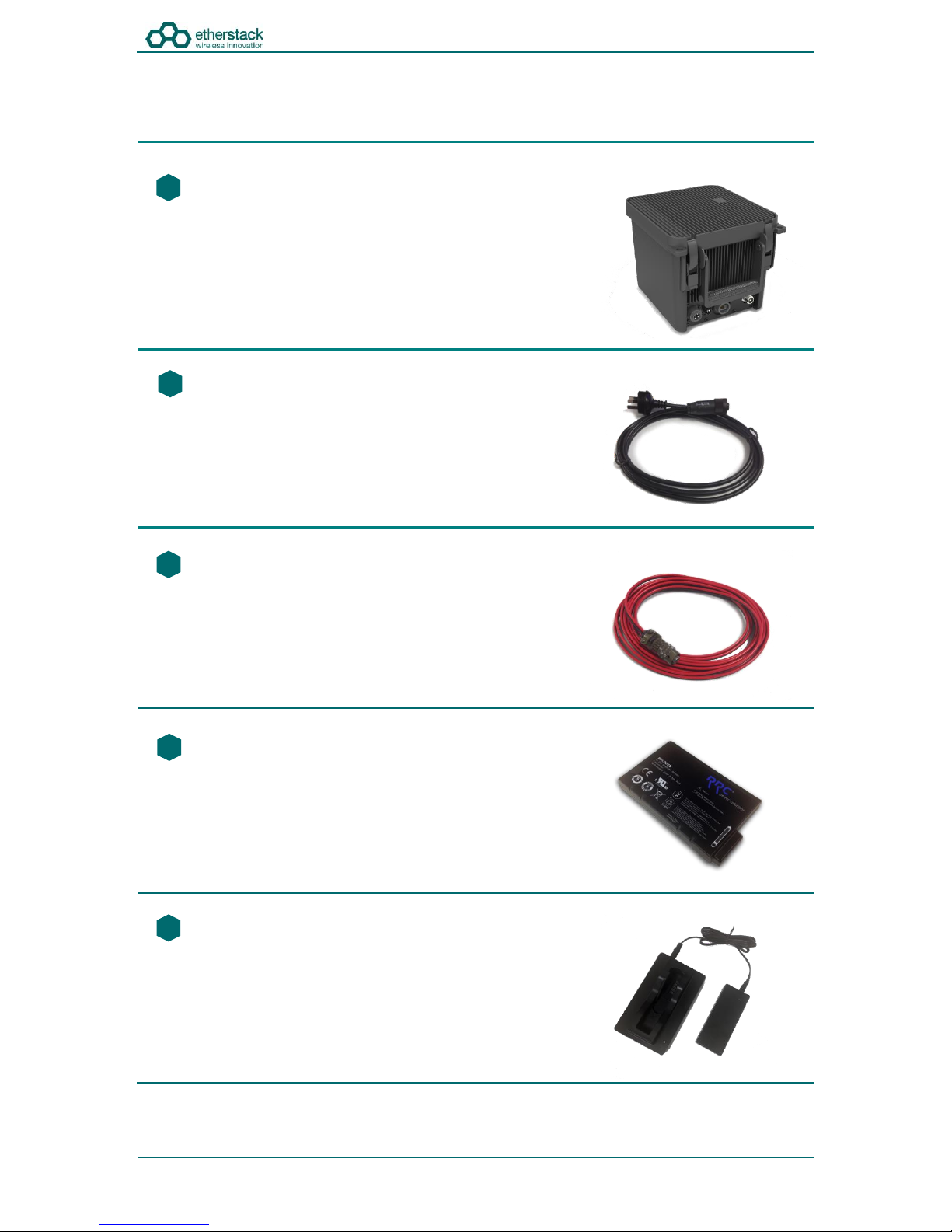
2.1 Package Contents
Go Box
The GoBox will be in the carry mode with its lid closed and both locking
clamps engaged.
The GoBox will be pre-fitted with a GoBox control module, GoBox radio
modules, GoBox Duplexer (in the band/frequency requested at time of
order), 15W power amplifier and dual hot swappable battery module.
AC Power Cable
The AC power cable will have a standard AC power plug for your country
of operation (requested at time of order) on one end and will have an
IP67 rated coupling socket for connection to the GoBox on the other.
DC Power Cable
The DC power cable will be pre stripped for connection to standard
telecommunications grade power supplies on one end and will have an
IP67 rated coupling socket for connection to the GoBox on the other.
2 x Lithium Ion Rechargeable Batteries
Each battery will require a full charge prior to first use.
It is recommended that any additional batteries be sourced through your
authorised reseller.
d
f
f
s
d
f
f
Lithium Ion Battery Recharger (Optional Accessory)
An external battery charger is available as an option.
1
2
3
4
5
SFFR-6 User Manual
Getting Started
Doc ID: ES1002-UM02-v204a
Copyright © 2014 Etherstack London Limited
Page 13 of 39
2.2 Getting to know your GoBox
2.2.1 Locking Clamps
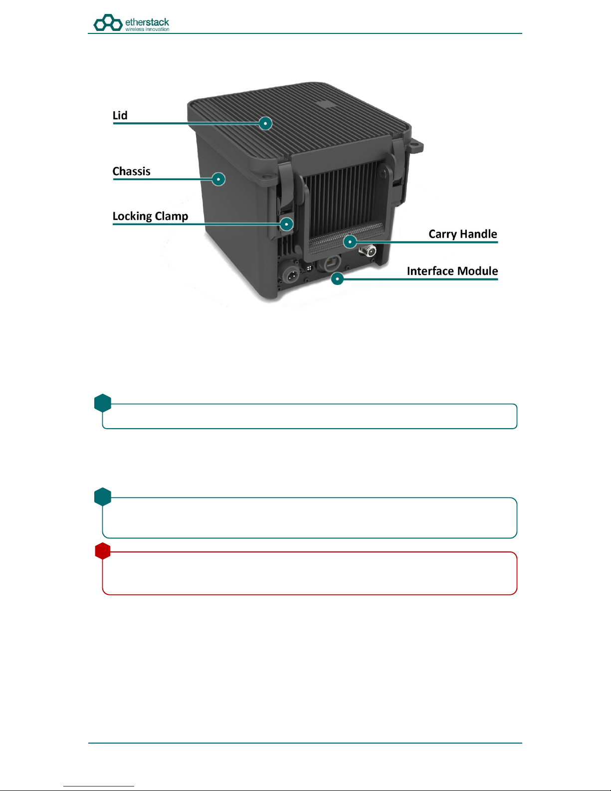
The GoBox has two locking clamps on either side of the Carry Handle to lock the lid firmly against the chassis.
To disengage the locking clamps, place your finger behind the clamps and pull away and up towards the lid. Lift the curved
section of the locking clamp up and out of the channel in the top of the lid and repeat for the other clamp to release the
GoBox lid.
2.2.2 Lid
The GoBox lid has been designed to prevent dust and water from entering the GoBox when the locking clamps are fully
engaged.
Both locking clamps must be fully engaged to ensure a correct seal.
!
Once the GoBox has been programed, the lid only needs to be opened to turn the GoBox on when powered under
batteries. The lid does not need to be closed during operation however it is recommended to be closed during
infield use.
!
The lid gasket located around the lid perimeter of the chassis must be kept clean and free of any debris. It should
be inspected before field operation and cleaned or replaced if damaged otherwise water or dust could penetrate
and damage GoBox electronics.
!
SFFR-6 User Manual
Getting Started
Doc ID: ES1002-UM02-v204a
Copyright © 2014 Etherstack London Limited
Page 14 of 39
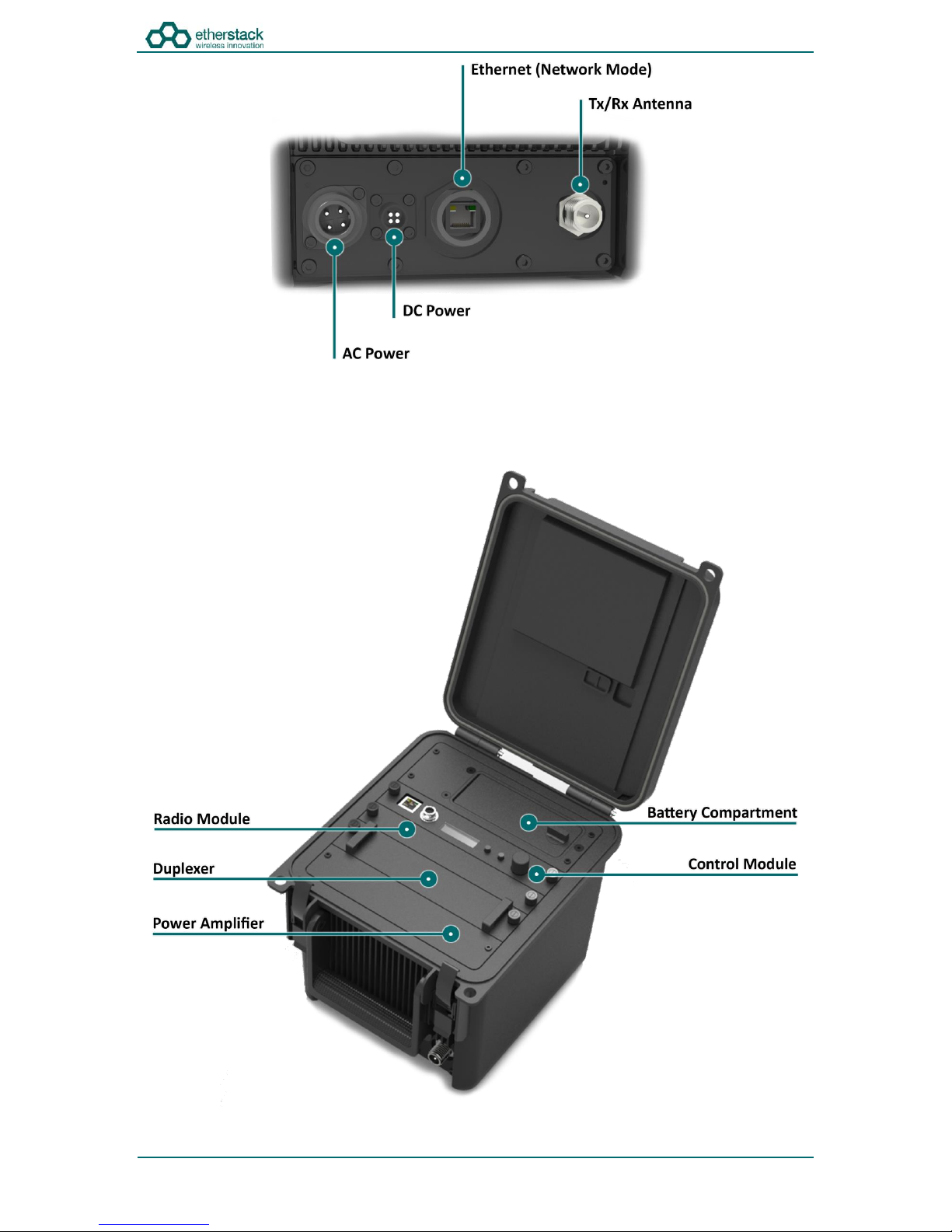
2.2.3 InterfaceModule
The interface module will vary based on the options purchased when your GoBox was ordered.
The interface module presents both AC and DC connectors, combined transmit and receive antenna connector or separate
transmit and receive antenna connectors and/or an Ethernet port for use in Network mode.
SFFR-6 User Manual
Getting Started
Doc ID: ES1002-UM02-v204a
Copyright © 2014 Etherstack London Limited
Page 15 of 39
2.2.4 BatteryCompartment
The battery compartment supports two lithium ion batteries and while only one battery is required to operate the GoBox it
is recommended to install two batteries to maximise run time when no AC or DC power is connected.
To open the battery compartment, turn the locking dial on the battery compartment 90 degrees counter clockwise and pull
up to access the battery compartment. To lock the battery compartment, lower the battery compartment lid and turn the
dial 90 degrees clockwise.
Each battery supplied will have a small nylon tag attached to the battery so it can be easily removed when installed in the
GoBox Battery Compartment.
Each battery also has a battery charge status indicator that can be activated by pressing the small button located on the
corner of the battery.
The battery compartment has also been designed to allow battery hot swapping to quickly replace an exhausted battery
source without the need to turn the GoBox off.
The battery compartment has also been designed to recharge batteries when an external power source is applied. Battery
charge and charging state is explained under the control module section below.
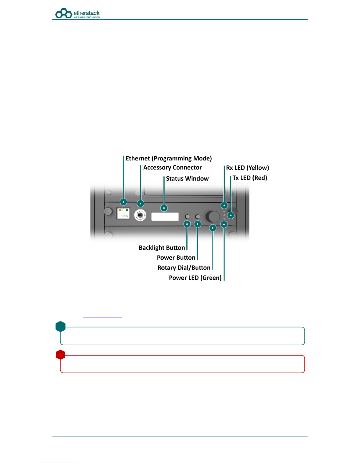
2.2.5 ControlModule
2.2.5.1 Ethernet(ProgrammingPort)
The Ethernet programming port is used to check GoBox status and to configure the GoBox.
Attach a standard Ethernet cable to this port with the other end connected directly to your laptop/PC. From your web
browser type http://172.16.10.1 to gain access to the GoBox configuration interface.
2.2.5.2 AccessoryConnector
The accessory connector is used to connect a local speaker microphone or short range wireless speaker microphone or
headset for operation with the GoBox.
For further information on available accessories please contact your authorised distributor.
Some corporate IT policies may prevent accessing this subnet from your laptop/PC either directly or across your
network. Please contact your local IT support team if you have trouble accessing the GoBox configuration interface.
!
Do not attach an Ethernet cable to both Ethernet ports on the GoBox at the same time to a switch/router as it may
cause some network switches/routers to fail.
!
SFFR-6 User Manual
Getting Started
Doc ID: ES1002-UM02-v204a
Copyright © 2014 Etherstack London Limited
Page 16 of 39
2.2.5.3 StatusWindow
The status window displays the currently selected operational profile, power level of each battery, status of the on-board
battery charger and external power source if AC and/or DC power is connected.
2.2.5.4 Backlight Button
The backlight button when pressed will engage the LCD backlight for several seconds so the LCD display can be more easily
viewed if external lighting conditions are poor.
2.2.5.5 PowerButton
The power button when pressed and held down will toggle the power status of the GoBox.
2.2.5.6 RotaryDialandButton
The rotary dial is used to quickly select different operational profiles.
On pressing the rotary dial, the status window backlight will automatically illuminate and remain on until the rotary dial
button is released. You can turn the dial to select any of the available and pre-configured profiles.
Once a profile has been found, releasing the rotary dial push button will commence a reconfiguration of the GoBox. During
this time the Green Power LED will flash indicating a reconfiguration is in progress. When the Green Power LED turns solid,
the GoBox is ready for operation.
2.2.5.7 TxandRXLED
On receiving a signal on the frequency the GoBox is programmed for, the yellow Rx LED will illuminate for the duration of
the signal. The red Tx LED will illuminate to indicate that the signal has been repeated.
2.2.5.8 PowerLED
On power-up, the GoBox will perform a series of self-tests to ensure all elements are operational. During this time the LED
will flash to indicate that power is on but he GoBox is not yet operational. Once the LED turns a solid Green, the GoBox is
ready for use.
2.2.6 RadioModule
The radio module houses two high performance radio transmitters and receivers. These modules are band specific and will
be pre fitted based on the frequency band of the duplexer fitted at the time of order.
The backlight is on a timeout to ensure it is not left on and otherwise drain the batteries unnecessarily.
!
The power button must be held done for several seconds to avoid accidental power on/off scenarios.
!
To avoid accidental profile changes, the rotary dial must be pressed during rotation.
!
Based on the configuration profile, the Tx LED may not illuminate.
!
The GoBox when first unpacked will not have any operational profiles to execute. Until the GoBox has been
configured, the Power LED will continue to flash, indicating it is in the programming state.
!
The GoBox radio modules have been designed to run at high temperatures in order to support the power output
and high duty cycles typical of a heavy use repeater/base station. Care must be taken if the GoBox has been
running for several hours supporting a large volume of calls. The front panel of the radio module can exceed 50oC.
!

SFFR-6 User Manual
Getting Started
Doc ID: ES1002-UM02-v204a
Copyright © 2014 Etherstack London Limited
Page 17 of 39
2.2.7 Duplexer
The GoBox will be fitted with a duplexer when the single antenna interface is fitted. The duplexer module will be tuned to
the centre frequency requested at the time of order to maximise RF performance.
Additional Duplexers in the same band can be ordered and swapped within minutes. Additionally the GoBox can auto
sense the installed duplexer and select the correct operational profile without any user interaction.
To remove the Duplexer, ensure the GoBox is off and all power sources removed. Turn the locking screws counter
clockwise to remove and lift the Duplexer module out.
2.2.8 Power Amplifier
The GoBox will be fitted with a power amplifier.
The Duplexer is not hot swappable. You must ensure the GoBox is powered down, batteries removed and all
external power sources disconnected before removing the Duplexer module.
!
The GoBox Power Amplifier has been designed to run at high temperatures in order to support the power output
and high duty cycles typical of a heavy use repeater/base station. Care must be taken if the GoBox has been
running for several hours supporting a large volume of calls. The chassis area located near the handle can get hot.
!

SFFR-6 User Manual
3Configuration
SFFR-6 User Manual
Configuration
Doc ID: ES1002-UM02-v204a
Copyright © 2014 Etherstack London Limited
Page 19 of 39
3.1 Before you begin
3.1.1 AboutGoBoxConfigurationFiles
The GoBox Configuration file is stored within the GoBox but you should develop a process to centrally backup and manage
this configuration file.
For users that maintain several GoBox’s, the configuration file can be shared and it is recommended that a single file be
used to simplify GoBox administration.
3.1.2 AboutOperationalProfiles
To use your GoBox you need to program at least one operational profile which can then be assigned to a duplexer for auto
selection on power-up.
Up to 50 operational profiles can be pre-loaded into the GoBox. Each operational profile contains all information
necessary to configure the GoBox.
Profiles can then be selected and activated by pressing and turning the rotary dial on the GoBox control interface to select
and activate that profile.
3.1.3 About Duplexer Group Tags
A unique duplexer tag can be programmed into a duplexer and then tagged to an operational profile to essentially link the
operational profile with the duplexer.
The GoBox will only display operational profiles whose duplexer group tag field has been set to the same tag group as what
is programmed in the duplexer.
Additionally, an operational profile can be assigned as the default operational profile for when a Duplexer is installed and
therefore when the GoBox powers up. This feature allows Duplexers to be easily moved around GoBox’s in the same band
and providing the configuration files are identical, the GoBox will automatically select the correct operational profile
without requiring any user intervention.
If your GoBox is ever damaged or you purchase additional units, your configuration file can be easily used to
reprogram a new GoBox within minutes.
!
Make sure you press and hold the rotary dial down when turning to select a new profile.
!
Operational profiles can also be backed up and restored over the network allowing easy transfer of profiles from
one GoBox to another
!
To setup multiple GoBox’s, we recommend using the following process on a single GoBox:
1. Write a Duplexer tag to each Duplexer
2. Add Duplexer Group Tags
3. Add Operational Profiles
4. Set the start-up profile for each Duplexer
5. Backup the configuration
6. Restore the configuration to the other GoBox’s
!
If an operational profile uses the All tag, the profile will always be visible in the GoBox control panel via the rotary
dial however its frequency may not be supported by the currently installed Duplexer
!
SFFR-6 User Manual
Configuration
Doc ID: ES1002-UM02-v204a
Copyright © 2014 Etherstack London Limited
Page 20 of 39
3.1.4 What you needto program and testyour GoBox
3.1.4.1 LaptoporPCwithan Ethernet Interface
The GoBox doesn’t not require any external programming application to be installed on your laptop/PC and does not
require a special programming cable.
A laptop or PC with a web browser and standard Ethernet cable is all that will be required to configure the GoBox. Once
configured the laptop is no longer required for GoBox operation.
3.1.4.2 Radios
Mobile and/or portable radios will be required to be programmed for the Duplexer frequency and other supported
operational parameters such as NACs configured in the GoBox.
A simple way to test GoBox operation is to simply PTT on a correctly programmed radio. If correctly programmed,
the GoBox Rx and Tx LEDs will illuminate.
!
Table of contents
Popular Accessories manuals by other brands

Winland Electronics
Winland Electronics WaterBug WBTX-319 installation instructions

Fisher Scientific
Fisher Scientific Isotemp 60L Incbtr Grvity 120V user manual

Jackson
Jackson Green Saver Series manual

Balluff
Balluff BCM R15E-00 Series user guide

G.I.KRAFT
G.I.KRAFT GI15111 instruction manual

Proxim
Proxim Tsunami MP-8100 Series Installation and management guide


