manuals.online logo
Brands
  1. Home
  2. •
  3. Brands
  4. •
  5. SECO-LARM
  6. •
  7. Accessories
  8. •
  9. SECO-LARM Enforcer SD-927PKC-NEQ User manual

SECO-LARM Enforcer SD-927PKC-NEQ User manual

Wave-to-Open Sensors
Installation Manual
SD-927PKC-NEVQ
SD-927PKC-NEQ
5024193
Conforms to
UL294
Model
Size
Operating Voltage
Override Button
SD
-
927PKC
-
NEQ
Single
-
gang
12~24 VAC/VDC
No
SD
-
927PKC
-
NEVQ
Single
-
gang
12~24 VAC/VDC
Yes
*Spanish and French faceplates also available.
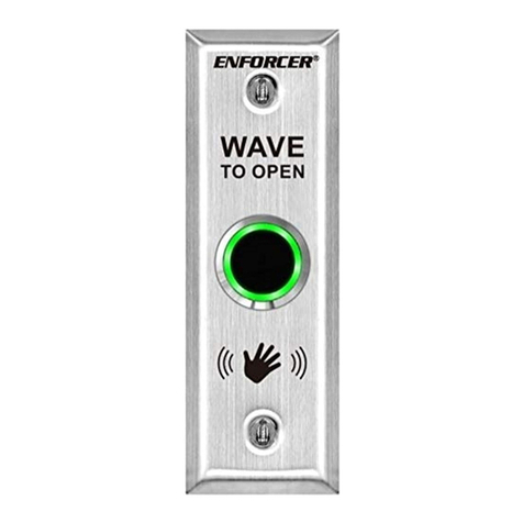
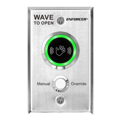
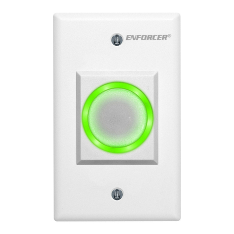
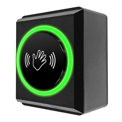
The ENFORCER Wave-To-Open Sensors use IR technology to request egress from a protected
area or activate a device with the simple wave of a hand. Since no touch is required, they are
suitable for use in hospitals, clinics, labs, cleanrooms (to reduce the risk of contamination),
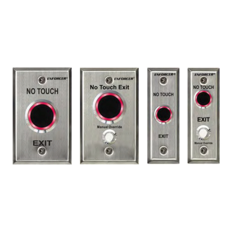
schools, factories, or offices. The SD-927PKC-NEVQ adds a manual override button as a backup
to the sensor. Also available with Spanish (SD-927PKC-NSQ, SD-927PKC-NSVQ) or French
(SD-927PKC-NFQ, SD-927PKC-NFVQ) faceplates.
 Operating voltage, 12~24 VAC/VDC
 Range adjustable from 23/8"~8" (6~20 cm)
 Stainless steel single-gang plate
 3A relay, adjustable from 0.5~30 sec, toggle, or as long as hand is near the sensor
 LED illuminated sensor area for easy identification
 Selectable LED colors (turns from red to green or green to red) when activated
 Quick connect screw-less terminal block
 Power must be provided by low-voltage power-limited/Class 2 power supply
 Use only low-voltage field wiring and do not exceed 98.5ft (30m)
Wave-to-Open Sensors
2 SECO-LARM U.S.A., Inc.
Parts List
1x
Wave
-
to
-
open sensor
2x
Mounting screws
3x
6" (5cm) Wire
connectors*
1x
Manual
*For override button, SD-927PKC-NEVQ only
Specifications
Model SD-927PKC-NEQ SD-927PKC-NEVQ
Operating voltage 12~24 VAC/VDC
Current 120mA@12VDC
Relay type Form C dry contact, 3A@24VDC
Override
button
Switching capacity N/A 3A@24VDC
Mechanical life N/A 500,000 cycles
Response time 10ms
LEDs Standby Red
Triggered Green*
Output duration Adjustable, 0.5~30 sec., toggle, or as long as sensor is triggered
Sensing range Adjustable, 23/8"~8" (6-20 cm)
Destructive attack level Level I
Line security Level I
Endurance level Level IV
Standby power Level I
Operating temperature -4°~131° F (-20°~55° C)
Weight 3-oz (85g) 3.9-oz (110g)
*Default, reversible by jumper
Installation
1. Run 4 wires through the wall to a single-gang back box. Power must
be provided by a low-voltage power-limited/Class 2 power supply
and low-voltage field wiring not to exceed 98.5ft (30m).
2. Connect the four wires from the back box to the quick connect
screw-less terminal according to Fig. 1.
3. Attach the plate to the back box, taking care not to crimp wires.
4. Remove clear protective film from the sensor before use.
INSTALLATION NOTES:
 This product must be electrically wired and grounded in accordance with
local codes or, in the absence of local codes, with National Electric Code
ANSI/NFPA 70-latest edition or the Canadian Electrical Code CSA C22.1.
 Due to the nature of IR technology, an IR sensor can be triggered by a
direct light source such as sunlight, reflected light from a shiny object, or
other direct light. Consider how to protect as needed.
Adjusting the Sensor Range and Output Timer (Fig. 2)
1. To adjust the sensor's range, turn its trimpot counterclockwise
(decrease) or clockwise (increase).
2. To adjust the output duration, turn its trimpot counterclockwise
(decrease) or clockwise (increase). To toggle, turn to minimum.
Adjusting the LED Color
1. The LED color factory default setting is red (standby) and green (triggered).
2. To reverse the LED color visual indicator to green (standby) and red triggered), remove the jumper
located at the right side of the terminal block as shown in Fig. 3.
Fig.1
Connections
(
under back
cover)
LED Color
adjustment jumper
Power Input Relay output (3A max.)
COM
NO
NC
(–) (+)
Fig.2 Output Duration /
Sensor
Range Potentiometers
Fig.3
LED Jumper Settings
Output duration
potentiometer
Sensor range
potentiometer
Terminal block
Red standby
(default)
Green standby
Wave-to-Open Sensors
SECO-LARM U.S.A., Inc. 3
12~24 VDC (+)
Ground (
-
)
COM
N.O.
Blue wire: COM to N.C.
Purple wire: N.O.
Green wire: N.C.
(–) (+)
COM
NO
NC
NC
NO
COM
12~24VDC
Power Supply
(–) (+)
Electric
Lock
(–
)
(+)
N.O.
N.C.
OR
12~24 VDC (+)
Ground (
-
)
COM
Manual Override Button
Override button COM (with red dot)
should be connected to the NC terminal
N.O.
Green: N
.
C
.
COM
NO
NC
The manual override button serves as a backup to the sensor
.
Purple:
N.O.
Blue:
COM to N.C.
A red dot
indicates COM
Sample Installations
Installation with Electromagnetic Lock
Installation with Electromagnetic Lock and Keypad
Override Button Wiring (SD-927PKC-NEVQ only)
ENFORCER
Access Control
Power Supply
SECO-LARM Series
Electromagnetic Lock
(Fail Safe)
NO
COM NC
WAVE TO OPEN
12
~24 VAC/
VDC
Power input
(–) (+)
(–) (+)
12VDC Battery
(optional)
SECO-LARM Series
Electric Strike
(Fail Secure)
(+)
Relay output
SECO
-
LARM
ENFORCER Access Control Power Supply
ENFORCER Keypad SECO-LARM Series
Electromagnetic Lock
(–) (+)
12VDC Battery
(optional)
WAVE TO OPEN
NO
COM NC
12~24 VAC/VDC
Power input
(–) (+)
Relay output
EGRESS
NO
COM
NC
(+)
Tamper
Output
(N.C.)
Wave-to-Open Sensors
Care and Cleaning
The sensor requires special care to ensure reliability and a long operating life.
1. Use a soft, clean cloth, preferably a microfiber cloth, to avoid scratching the sensor.
2. Use the mildest cleaner available. Strong cleaning chemicals may damage the sensor.
3. When cleaning, spray the cleaning solution onto the cleaning cloth instead of the unit.
4. Wipe any excess liquid from the sensor. Wet spots may affect the sensor’s performance.
Troubleshooting
Sensor triggers
unexpectedly
 Ensure that no strong direct or reflected light source is reaching the sensor.
 Ensure that sensor is sheltered from direct sunlight.
Sensor remains
triggered
 Check that nothing is remaining in range of the sensor including a cone of 60º
from the centerline.
 Reduce the IR range of the sensor.
 Ensure that the sensor's output duration potentiometer is not turned to maximum
 Check that the power voltage is within the sensor's specifications.
Sensor will not
trigger
 Increase the IR range of the sensor.
 Check that the power voltage is within the sensor's specifications.
Overview
11/8" (28mm)
21/8"
(55mm)
13/4" (44mm)
11/8" (28mm)
21/8"
(55mm)
13/4" (44mm)
SD-927-PKC-NEVQ
SD-927-PKC-NEQ
13/16"
(30mm)
SECO-LARM ® U.S.A., Inc.
16842 Millikan Avenue, Irvine, CA 92606
Website:
www.seco
-
larm.com
Phone: (949) 261-2999 | (800) 662-0800 Email: sales@seco-larm.com
PICPN3
MI_SD-927PKC-NExQ_220901.docx
WARRANTY: This SECO-LARM product is warranted against defects in material and workmanship while used in normal service for one (1) yea
r from the date of sale
to the original customer. SECO-LARM’s obligation is limited to the repair or replacement of any defective part if the unit is returned, transportation prepa
id, to
SECO-LARM. This Warranty is void if damage is caused by or attributed to acts of God, physical or electrical misuse or abuse, neglect, rep
air or alteration, improper
or abnormal usage, or faulty installation, or if for any other reason SECO-LARM determines that such eq
uipment is not operating properly as a result of causes other
than defects in material and workmanship. The sole obligation of SECO-
LARM and the purchaser’s exclusive remedy, shall be limited to the replacement or repair
only, at SECO-LARM’s option. In no event shall SECO-
LARM be liable for any special, collateral, incidental, or consequential personal or property damage of any kind
to the purchaser or anyone else.
NOTICE: The SECO-LARM policy is one of continual development and improvement. For that reason, SECO-
LARM reserves the right to change specifications without
notice. SECO-LARM is also not responsible for misprints. All trademarks are the property of SECO-LARM U.S.A., Inc. or their respective owners. Copyright © 2022
SECO-LARM U.S.A., Inc. All rights reserved.
California Proposition 65 Warning: These products may contain chemicals which are known to
the State of California to cause cancer and birth defects or other
reproductive harm. For more information, go to www.P65Warnings.ca.gov.
IMPORTANT: Users and installers of this product are responsible for ensuring that the installation and configuration of this product com
plies with all national, state,
and local laws and codes. SECO-LARM will not be held responsible for the use of this product in violation of any current laws or codes.
IMPORTANT WARNING: Incorrect
mounting which leads to exposure to rain or moisture inside the enclosure could cause a dangerous electric shock, damage the
device, and void the warranty. Users and installers are responsible for ensuring that this product is properly installed and sealed.
Other manuals for Enforcer SD-927PKC-NEQ

1

This manual suits for next models

1

Other SECO-LARM Accessories manuals

SECO-LARM SD-9163-KSQ User manual

SECO-LARM

SECO-LARM SD-9163-KSQ User manual

SECO-LARM ENFORCER E-931-S45RRQ User manual

SECO-LARM

SECO-LARM ENFORCER E-931-S45RRQ User manual

SECO-LARM ENFORCER CS-PD115-PAQ Installation guide

SECO-LARM

SECO-LARM ENFORCER CS-PD115-PAQ Installation guide

SECO-LARM SD-9163-KSQ User manual

SECO-LARM

SECO-LARM SD-9163-KSQ User manual

SECO-LARM SLI ENFORCER E-931-S50RRGQ User manual

SECO-LARM

SECO-LARM SLI ENFORCER E-931-S50RRGQ User manual

SECO-LARM ENFORCER SD-R400-BQ User manual

SECO-LARM

SECO-LARM ENFORCER SD-R400-BQ User manual

SECO-LARM ENFORCER SM-200Q/W User manual

SECO-LARM

SECO-LARM ENFORCER SM-200Q/W User manual

SECO-LARM SD-9163-KSQ User manual

SECO-LARM

SECO-LARM SD-9163-KSQ User manual

SECO-LARM Enforcer SM-205Q/W User manual

SECO-LARM

SECO-LARM Enforcer SM-205Q/W User manual

SECO-LARM SD-927PWCQ User manual

SECO-LARM

SECO-LARM SD-927PWCQ User manual

SECO-LARM Push-To-Exit Bar SD-969-A18 User manual

SECO-LARM

SECO-LARM Push-To-Exit Bar SD-969-A18 User manual

SECO-LARM Push-to-Exit Bar SD-961A-36 User manual

SECO-LARM

SECO-LARM Push-to-Exit Bar SD-961A-36 User manual

SECO-LARM RA-4961-MBQ User manual

SECO-LARM

SECO-LARM RA-4961-MBQ User manual

SECO-LARM ENFORCER CS-PD535-TAQ User manual

SECO-LARM

SECO-LARM ENFORCER CS-PD535-TAQ User manual

SECO-LARM ENFORCER E-961-S90WQ User manual

SECO-LARM

SECO-LARM ENFORCER E-961-S90WQ User manual

SECO-LARM Enforcer SD-7251GCEX1Q User manual

SECO-LARM

SECO-LARM Enforcer SD-7251GCEX1Q User manual

SECO-LARM ENFORCER E-9626-2B190Q User manual

SECO-LARM

SECO-LARM ENFORCER E-9626-2B190Q User manual

SECO-LARM SLI ENFORCER E-936-S45RRGQ User manual

SECO-LARM

SECO-LARM SLI ENFORCER E-936-S45RRGQ User manual

SECO-LARM ENFORCER E-931-S33PRGQ User manual

SECO-LARM

SECO-LARM ENFORCER E-931-S33PRGQ User manual

SECO-LARM ENFORCER SM-205Q/W User manual

SECO-LARM

SECO-LARM ENFORCER SM-205Q/W User manual

SECO-LARM E-931-S33PRQ User manual

SECO-LARM

SECO-LARM E-931-S33PRQ User manual

Popular Accessories manuals by other brands

IFM LMT 0 Series operating instructions

IFM

IFM LMT 0 Series operating instructions

Doran 2200 Series instruction manual

Doran

Doran 2200 Series instruction manual

Baumer UNAM 12P3914/S14 manual

Baumer

Baumer UNAM 12P3914/S14 manual

Dometic CK40D Hybrid operating manual

Dometic

Dometic CK40D Hybrid operating manual

Performance Tool W1677 owner's manual

Performance Tool

Performance Tool W1677 owner's manual

Rice Lake 420 Plus installation manual

Rice Lake

Rice Lake 420 Plus installation manual

HOLZMANN MASCHINEN HMS 700 user manual

HOLZMANN MASCHINEN

HOLZMANN MASCHINEN HMS 700 user manual

KSI JD Air Cart Owner's/operator's manual

KSI

KSI JD Air Cart Owner's/operator's manual

5.11 Tactical LV6 Attachment Manual

5.11 Tactical

5.11 Tactical LV6 Attachment Manual

Pico Macom TSC Specifications

Pico Macom

Pico Macom TSC Specifications

Philips DLA71055 brochure

Philips

Philips DLA71055 brochure

NEO Coolcam iDoorbell Quick installation guide

NEO Coolcam

NEO Coolcam iDoorbell Quick installation guide

Bartington Mag-13 Operation manual

Bartington

Bartington Mag-13 Operation manual

Opticstar EQ700 instruction manual

Opticstar

Opticstar EQ700 instruction manual

quadient AS-CSD6 user guide

quadient

quadient AS-CSD6 user guide

Milesight WS52 Series quick start guide

Milesight

Milesight WS52 Series quick start guide

Axis AXDL-100 Manual guide

Axis

Axis AXDL-100 Manual guide

PCB Piezotronics TORKDISC 5308D-140-02A Installation and operating manual

PCB Piezotronics

PCB Piezotronics TORKDISC 5308D-140-02A Installation and operating manual

manuals.online logo
manuals.online logoBrands
  • About & Mission
  • Contact us
  • Privacy Policy
  • Terms and Conditions

Copyright 2025 Manuals.Online. All Rights Reserved.