ETI Snow Switch EUR-5A User manual

South Bend, Indiana USA | networketi.com SNOW/ICE CONTROL INSTALLATION GUIDE | PART NO. 25161 REV 0.0
PACKING LIST
QTY. PART NO. DESCRIPTION
1 21496 EUR–5A Snow and Ice Melting Control
1 25076 High Temperature Limit Sensor
1 14257 Power Transformer, 50 VA, 120 V to 24 V
1 21357 RCU–3 Remote Control
121184 Fuse Kit
121776 EUR–5A Installation Guide ( this document )
DETERMINING THE AMOUNT OF SENSORS YOU
CAN USE
The EUR–5A has 46 watts of power available for
use between the sensors and contactor. The power
requirement of your contactor will determine the amount
of watts left available for your sensors. After determining
your contactor’s power requirement, subtract that from
the 46 available watts, the result will be your available
power for your sensors. You can then take your available
power and use that to determine the number of sensors
you can use.
• Each CIT–1 aerial sensor (at least one is required) uses
2.4 watts of power
• Each GIT–1 gutter sensor uses 6 watts of power
• Each SIT–6E pavement sensor uses 6 watts of power
At least one CIT–1 Areal sensor is required for an effective
snow/ice melt system. Make sure your combined sensor
and contactor’s power use does not exceed 46 watts.
ENVIRONMENTAL SENSORS
The use of sufcient appropriately-placed environmental
sensors is important for effective and efcient system
operation. An aerial snow sensor can give the system
a head start in protecting against snow or ice buildup,
yielding more consistent protection.
MODEL EUR™
-5A
AUTOMATIC SNOW/ICE MELTING SYSTEM CONTROL PANEL
Copyright © 2019 ETI,
®
All rights reserved.

South Bend, Indiana USA | networketi.com SNOW/ICE CONTROL INSTALLATION GUIDE | PART NO. 25161 REV 0.0
2
INSTALLATION
The system installation with the EUR–5A snow and ice
melting control should be performed by a qualied,
licensed electrician. The installation and all electrical
connections should conform to the NEC (ANSI/NFPA
70) in the United States of American, to the Canadian
Electrical Code in Canada, and to all applicable local
electrical codes and laws.
The EUR–5A and ETI sensors are Class 2 devices and
utilize Class 2 wiring. The EUR–5A should be housed in
a protected location that meets local electrical code.
The EUR–5A can be mounted in the same panel as the
heater contactors, as long as no unrelated circuits are
present and the required internal spacings and barriers
are implemented. If the EUR–5A needs to be located in an
area where it might be exposed to environmental hazards
the EUR–5A should be housed in a NEMA enclosure
suited for the local environment.
Make sure that your installation and all electrical connections conform to the NEC (ANSI/NFPA 70) in the
United States of American, to the Canadian Electrical Code in Canada, and to all applicable local electrical
codes and laws. The EUR–5A, RCU–3, and ETI environmental sensor are all rated as NEC Class 2 devices.

South Bend, Indiana USA | networketi.com SNOW/ICE CONTROL INSTALLATION GUIDE | PART NO. 25161 REV 0.0
3
1. POWER SOURCE AND CONTACTOR CONNECTIONS
(Terminals 21, 22, 36 and 37)
The EUR–5A operates from a 24 VAC NEC Class 2 power
source. The optional 120 to 24 volt control transformer is
included for use in installations using 120 VAC power.
Figure 5 shows power and contactor connections for a
typical installation. Since the EUR–5A is an NEC Class 2
device, it usually requires a customer-supplied auxiliary
relay for operating the heater control contactors to
separate the Class 2 circuit from the power circuits.
In case your installation is different and the necessary
connections to the EUR–5A are unclear, Customer Service
is available for assistance.
2. INLINE FUSE CONNECTIONS
(Terminals 26, and 36)
The supplied inline fuses, rated at 2.0 amps, are used to
protect the EUR–5A and its connected devices. Figure 6
shows how these are connected. One of them is in series
with the 24-volt supply to the EUR–5A. The other is in series
with the 24-volt supply connection to the environmental
sensors that use power (this power source is full-wave
rectied). These fuses are necessary to protect the EUR–
5A from an overload or short in the sensor or its wiring.
The 24 VAC Return is not ground; a oating ac power
source, such as the transformer secondary, is used here.
3. GROUNDING
(Terminals 18, or 19)
The EUR–5A sensor circuits and the EMC inputs are
referenced to a common circuit ground. In most situations
this part of the system can be left oating from the building
panel ground (not connected to it).In some cases, noise or
transient immunity may be improved if the EUR–5A (with
its sensors) is actually grounded to the building ground.
But this can create a voltage difference on the sensors
because of the difference in the electrical potential of
the building ground and the outdoor building structures
contacting the sensors creating a ground loop. To avoid
this potential ground loop install a resistor, such as 100
ohms, between the EUR–5A ground terminal (18 or 19)
and the building panel ground.
FIGURE 5. Power
and contactor
connections
FIGURE 6. Inline Fuse connections
FIGURE 7. EUR–5A
unit ground to
Building Panel
Ground with 100
ohm resistor

South Bend, Indiana USA | networketi.com SNOW/ICE CONTROL INSTALLATION GUIDE | PART NO. 25161 REV 0.0
4
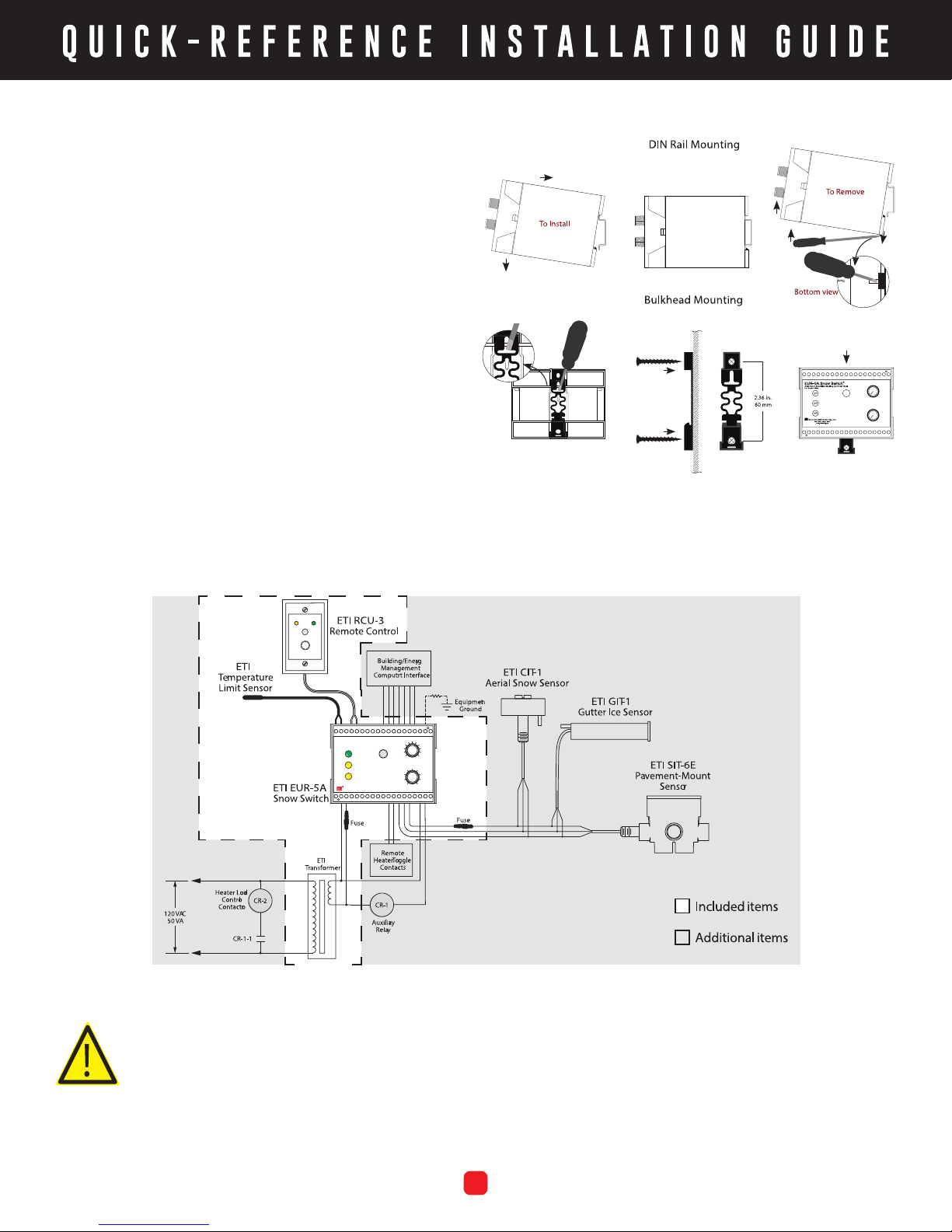
4. ENVIRONMENTAL SENSORS
(Terminals 24, 25, and 26)
Sensors are all connected in parallel. Use #18 AWG
extension wire for distances up to 1000 ft. (304.8m) and
#12 for up to 2000 ft. (609.6m). Running sensor wiring
and power line voltage wiring in the same conduit is not
recommended.
5. HIGH TEMPERATURE LIMIT SENSOR
(Terminals 1, and 2)
The high temperature limit sensor is connected across
terminals 1 and 2. There is no polarity requirement.
If the high temperature limit sensor is not used, then a
470k ohm resistor must be connected in its place, across
terminals 1 and 2 of the EUR–5A. This is necessary to allow
the EUR–5A to operate without the sensor. If the circuit
is left open, the Heat indicator on the EUR–5A panel will
ash and the control will be disabled.
6. RCU–3 INSTALLATION
(Terminals 4, and 5)
The RCU–3 remote control unit mounts in a single gang
switch box. It can be located up to 500 feet (152.4 m)
from the EUR–5A at a location convenient for observing
snow melting system operation. The RCU–3 connects
to the EUR–5A at terminals 4 and 5. There is no polarity
requirement.
7. REMOTE HEATER TOGGLE CONNECTIONS
(Terminals 28, and 29)
This is for a user-supplied panel-mounted momentary
pushbutton switch for Heater Cycle control. It can be
mounted at a location that may be more convenient than
the EUR–5A panel. The connections are simply shorted
together when the pushbutton is pressed. There is no
polarity requirement.
8. ENERGY MANAGEMENT COMPUTER INTERFACE
(Terminals 10, 11, 12, 13, 14, 15, and 16)
The EUR–5A provides three contact-closure outputs to
the EMC to indicate operational status with indications of
Supply Present, Snow Present, and Heat On. These oating
relay contacts share a common connection (terminal 13).
• The SUPPLY PRESENT terminal (14) connects to the
common terminal (13) when the EUR–5A is receiving
24- volt power.
• The SNOW PRESENT terminal (15) connects to the
common terminal (13) when the sensors report the
presence of ice or snow.
• The HEATER ON terminal (16) connects to the common
terminal (13) while the heaters are on. When connecting
to ECM connect as follows:
• OVERRIDE ON: when the ECM connects terminals 10
and 11 this forces the heaters to be on.
• OVERRIDE OFF: when the ECM connects terminals 10
and 12 this forces the heaters to be off.
CONTACTING CUSTOMER SERVICE
For technical help, questions or comments concerning
this product or any ETI product contact Customer Service
8:00 a.m. - 5:00 p.m. EST.
Email: [email protected]
Web: networketi.com
Mail: ETI
1850 North Sheridan Street
South Bend, IN 46628
LIMITED WARRANTY
ETI’s two year limited warranty covering defects in
workmanship and materials applies. Contact Customer
Service for complete warranty information.
DISCLAIMER
ETI makes no representations or warranties, either
expressed or implied, with respect to the contents
of this publication or the products that it describes,
and specically disclaims any implied warranties of
merchantability or tness for any particular purpose. ETI
reserves the right to revise this publication, and to make
changes and improvements to the products described
in this publication, without the obligation of ETI to notify
any person or organization of such revisions, changes or
improvements.
Other manuals for Snow Switch EUR-5A
1
Other ETI Control Panel manuals