ETI 51405143 User manual

F
Green
White(N)
Black(L)
G
C
F
H
A
G
Model # 51405143, 51405144
Part # SC-2HD-2400LM-8-40K-SV-BZ, SC-2HD-2400LM-8-40K-SV-W
Certification # 51405143, 51405144
USE AND CARE GUIDE
2 HEAD LUMEN BOOST DUSK TO DAWN SECURITY LIGHT
NOTE: Keep your receipt and these instructions for proof of purchase.
WARNING: Shut off the power at the circuit breaker or fuse panel before removing the old fixture,
ballast, or fluorescent tubes.
If you are unfamiliar with electrical installations, we recommend you contact a qualified electrician to
do the installation.
INSTALLATION
This light fixture is suitable for wall mounting or eave mounting only. It is not suitable for ground
mounting installation. The light fixture should be mounted a minimum of 6.5 ft. (2.0 m) above the
ground. If two walls intersect, than the distance between the intersecting line and the light fixture
should be more than 2 ft. (0.6 m).
Shut off power at the electrical panel before beginning the installation.
Remove existing fixture and set aside to recycle in accordance with local requirements.
Choose the desired brightness (lumen output).
NOTICE: The factory setting for the brightness (lumen output) is 2400lm.
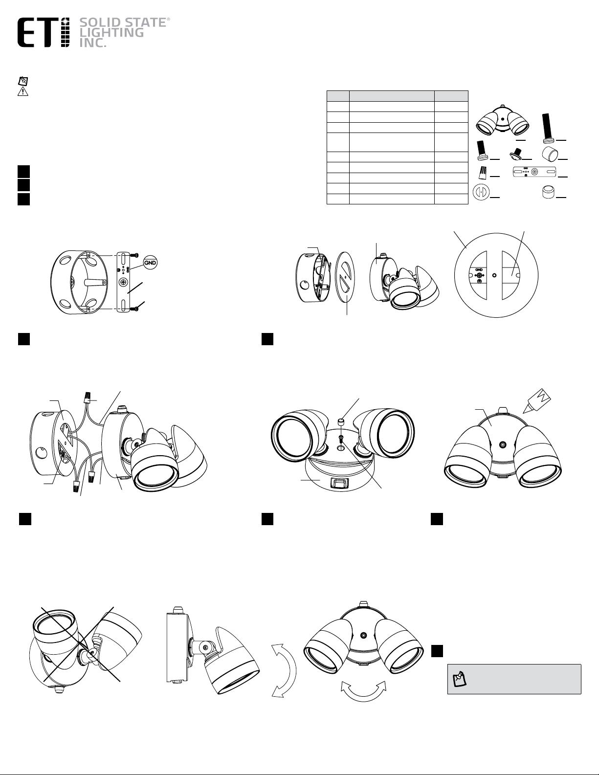
Attach the mounting bracket (G) to the electrical box using the
two short mounting screws (C). The stamped word “GND” faces
away from the electrical box during the installation.
45
PACKAGE CONTENTS
Part Description Quantity
A Fixture 1
B Mounting Screw (long) 1
C Mounting Screw (short) 2
D Grounding Screw (green) 1
E Rubber Plug 1
F Wire Connector 3
G Mounting Bracket 1
H Foam Gasket 1
I Rubber Cover 1
1
2
Connect the hot and neutral (black and white) wires from the light
fixture (A) to the same color wires from the electrical box.
Connect the ground wire from the light fixture (A) to the ground
wire from the electrical box, then attach the ground wire to the
grounding screw (D) on the mounting bracket (G).
Cover the wire connections using the wire connectors (F).
6
Position the foam gasket (H) between the electrical box and the back of the light fixture (A) to create a
weathertight seal.
Pull the wires from the electrical box through one of the two openings in the foam gasket (H).
8Apply silicone sealant (not included) to
the edges of the light fixture (A) so that
the fixture can be completely waterproof
and dustproof.
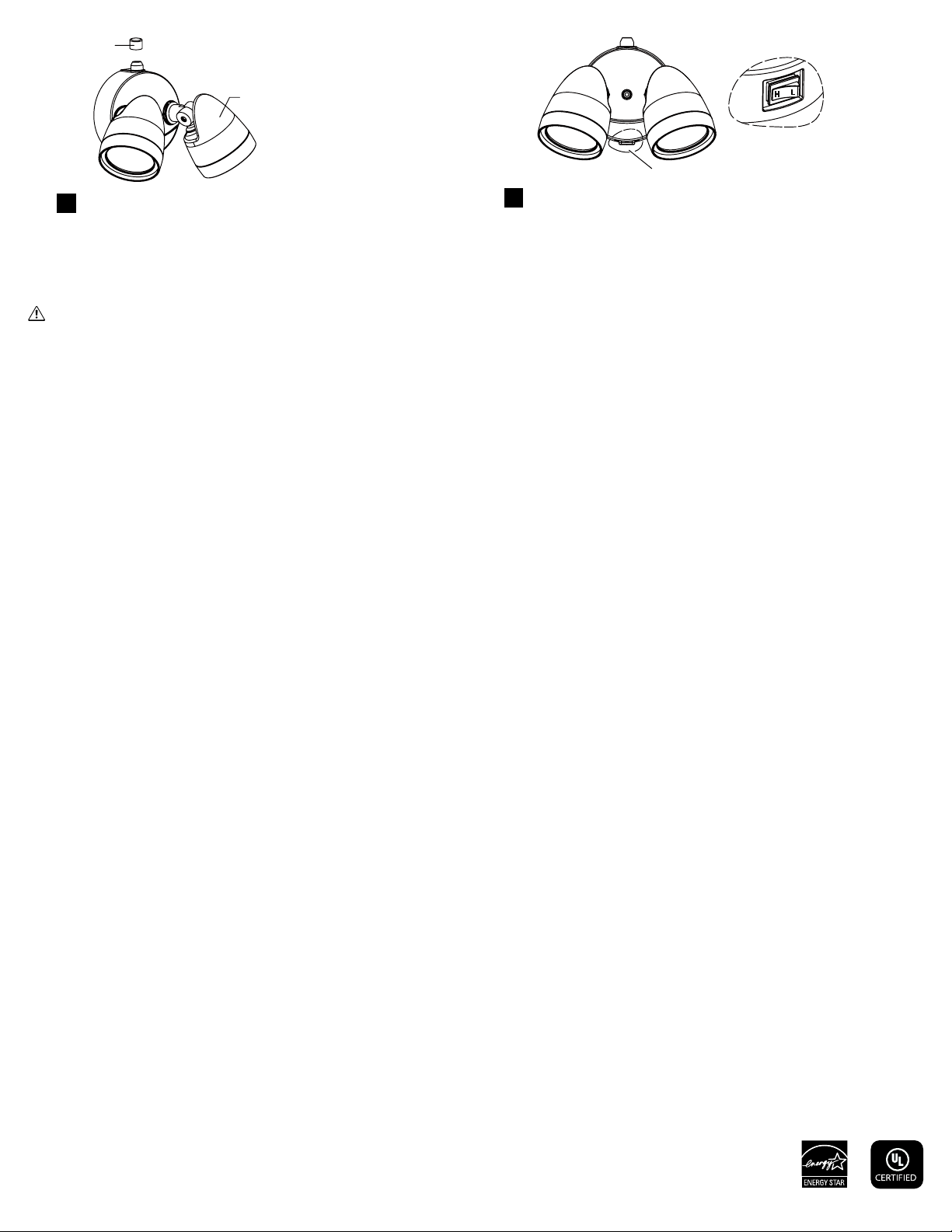
Move each light head into the desired
position with your hand, as needed.
NOTE: Do not mount the photocell
sensor in the down position.
Install the light fixture (A) to the mounting
bracket (G) using the mounting screw (long)
(B) provided, making sure no wires are visible
outside the light fixture (A).
Insert the rubber plug (E) into the hole on the
light fixture (A) for a finished appearance.
9
3
A B
C D E
H
G
I
7
HG
G
A
H
E
A
C
A
E
WARNING: Carefully read and understand the information given in this manual before beginning the assembly and installation. Failure to do so could lead to electric shock, fire, or
other injuries which could be hazardous or even fatal. • Ensure the electricity to the wires you are working on is shut off. Either remove the fuse or turn off the circuit breaker.
NOTICE: This device complies with Part 15 of the FCC Rules. Operation is subject to the following two conditions: (1) this device may not cause harmful interference, and (2) this device
must accept any interference received, including interference that may cause undesired operation. These limits are designed to provide reasonable protection against harmful interference
in a residential installation. This equipment generates, uses and can radiate radio frequency energy and, if not installed and used in accordance with the instructions, may cause harmful
interference to radio communications. However, there is no guarantee that interference will not occur in a particular installation. If this equipment does cause harmful interference to radio
or television reception, which can be determined by turning the equipment off and on, the user is encouraged to try to correct the interference by one or more of the following measures:
Reorient or relocate the receiving antenna, increase the separation between the equipment and the receiver, connect the equipment into an outlet on a circuit different from that to which
the receiver is connected, and consult the dealer or an experienced radio/TV.
• Changes or modifications not expressly approved by the party responsible for compliance could void the user’s authority to operate the equipment.
See website for Warranty, Troubleshooting or Care and Cleaning details at www.ETiSSL.com.
Questions, problems, missing parts? Call ETiSSL Customer Service 8 a.m. - 5 p.m., CST, Monday - Friday
1-855-ETI-SSLI (1-855-384-7754) www.ETiSSL.com
This security light allows you to customize the brightness using 2 settings:
•H with 100% Brightness, L with 50% Brightness.
•Move the toggle switch at the bottom of the fixture to make your selection.
11
U.S.A. Patent 10091855
Use the rubber cover (E) to cover the photocell if switch
controlled use is preferred.
10
AHL
toggle switch
G
C
HG
G
A
H
F
Verde
Blanco(N)
Negro(L)
H
A
G
E
A
C
A
F
A B
C D E
H
G
I
Modelo # 51405143, 51405144
Parte # SC-2HD-2400LM-8-40K-SV-BZ, SC-2HD-2400LM-8-40K-SV-W
Certificación # 51405143, 51405144
MANUAL DE USO Y CUIDADO
LÁMPARA DE SEGURIDAD DOSCABEZA CREPÚSCULO A ALBA LUMEN BOOST
NOTA: Guarde el recibo de compra y estas instrucciones como prueba de compra.
ADVERTENCIA: Apague la corriente en el cajetín de interruptores automáticos o fusibles
antes de retirar el viejo accesorio, balastro o tubos fluorescentes.
Si no está familiarizado con las instalaciones eléctricas, le recomendamos que haga que un
electricista calificado se ocupe de la instalación.
INSTALACIÓN
Esta lámpara es adecuada para montaje en pared o en alero solamente. No es adecuado para
la instalación de montaje en suelo. La lámpara debe montarse a un mínimo de 6.5 pies (2,0
m) sobre el suelo. Si dos muros se intersecan, la distancia entre la línea de intersección y la
lámpara debe ser de más de 2 pies (0,6 m).
Corte el suministro en el panel eléctrico antes de comenzar la instalación.
Retirar el aparato existentes y apartarlos para reciclar según los requerimientos locales.
Elija el brillo deseado (salida de lúmenes).
AVISO: El ajuste de fábrica para el brillo (salida de lúmenes) es 2400 lm.
45
CONTENIDO DEL PAQUETE
Pieza Descripción Cantidad
A Lámpara 1
B Tornillo de montaje (largo) 1
C Tornillo de montaje (corto) 2
D Tornillo de puesta a tierra
(verde)
1
E Tapón de goma 1
F Conector de cable 3
G Soporte de montaje 1
H Junta de espuma 1
I Cubierta de goma 1
Conecte el cable energizado y el neutro (negro y blanco) de a
placa de fijación a los cables del mismo color de la caja eléctrica.
Conecte el cable de tierra de la base de la lámpara (A) al cable
de tierra de la caja eléctrica, y después al tornillo de tierra (D) del
soporte de montaje (G).
Cubra las conexiones de los cables usando los conectores de
cables (F).
6
Ponga la junta espumada (H) entre la caja eléctrica y la parte posterior de la base de la lámpara (A)
para crear un sello hermético.
Tire los cables a través de uno de los dos orificios en la junta espumada (H).
8Aplique el sellador de silicona (no incluido)
a los bordes de la base de la lámpara
(A) para asegurar que la lámpara esta
totalmente estanca al agua y al polvo.
7Coloque la base de la lámpara (A) sobre el
soporte de montaje (G) usando el tornillo de
montaje largo (G) suministrado, asegúrese
de que todos los cables son disimulados en la
lámpara (A).
Inserte el tapón de goma (E) en el orificio en
la base de la lámpara (A) para una aparencia
acabada.
9Mueve la cabeza de lámpara en la posición
deseada con la mano, según sea necesario.
NOTA : No instale el sensor de la
fotocélula en la posición
inferior.
1
2
3
Sujete el soporte de montaje (G) a la caja eléctrica usando los
dos tornillos de montaje cortos (C).
La palabra estampada “GND” encara lejos de la caja eléctrica
durante la instalación.

ADVERTENCIA: Lea cuidadosamente y comprenda la información incluida en este manual antes de comenzar el armado e instalación. No hacerlo puede provocar descarga
eléctrica, incendio, u otras lesiones que pueden ser peligrosas o incluso fatales. • Asegúrese de cortar el suministro eléctrico en los cables con los que trabajará. Extraiga los fusibles
o apague el cortacircuitos.
AVISO: Este dispositivo cumple con la Parte 15 de las Reglas de la FCC. El funcionamiento está sujeto a las siguientes dos condiciones: (1) este dispositivo no puede causar
interferencias perjudiciales y (2) este dispositivo debe aceptar cualquier interferencia recibida, incluidas las interferencias que puedan causar un funcionamiento no deseado. Estos límites
se establecen para brindar protección razonable contra interferencia dañina en una instalación residencial. Este equipo genera, utiliza y puede irradiar energía de frecuencias de radio y,
si no se instala conforme a las instrucciones, puede provocar interferencia dañina a las comunicaciones de radio. Sin embargo, no existe garantía de que la interferencia no se produzca
en una instalación en particular. Si este equipo produce interferencia dañina a la recepción de radio o televisión, lo que puede determinarse encendiendo y apagando el equipo, se insta
al usuario a intentar corregir la interferencia mediante uno de los siguientes métodos: Cambie la orientación o ubicación de la antena receptora. Aumente la separación entre el equipo y
el receptor. Conecte el equipo en un tomacorriente que esté en un circuito diferente al cual está conectado el receptor. Consulte con el representante o con un técnico experimentado en
radio y televisión para solicitar asistencia.
• Cambios o modificaciones no aprobadasen forma expresa por la parte responsable del cumplimiento puede invalidar la autoridad del usuario de manejar el equipo.
Las informaciones sobre la garantía, la solución de problemas, el mantenimiento y la limpieza se puede encontrar en el sitio web: www.ETiSSL.com.
Preguntas, problemas, piezas faltantes? Llame al Centro de Atención al Cliente de ETi en el horario de 8 a.m. - 5 p.m., HSC, de lunes a viernes.
1-855-ETI-SSLI (1-855-384-7754) www.ETiSSL.com
Patente de los EE.UU.
E
Esta lámpara de seguridad le permite personalizar el brillo utilizando 2
configuraciones:
•H con 100% de brillo, L con 50% de brillo.
•Mueva el interruptor de palanca en la parte inferior del dispositivo para
hacer su selección.
11
Si se prefiere el uso controlado por interruptor, use la cubierta de goma (E)
para cubrir la fotocélula.
10
AHL
Interruptor de palanca
This manual suits for next models
3
Table of contents
Languages:


