Etlin-Daniels EC302WHM-A13-BB-GU-10RC User manual

Head Ofce - 1850 Wilson Ave. · Toronto, ON · M9M 1A1 · Tel: 416.741.7336 · Fax: 416.741.9104 ·
Toll Free: in Canada. 1.800.661.9610 · in USA. 1.888.762.5384 (SOCKETS4U)
SAVE THESE INSTRUCTIONS - READ ALL INSTRUCTIONS CAREFULLY
IMPORTANT SAFEGUARDS
READ AND FOLLOW ALL SAFETY INSTRUCTIONS
• Review the diagrams thoroughly before beginning.
• All electrical connections must be in accordance with local codes, ordinances and
the National Electric Code.
• Disconnect power at fuse or circuit breaker before installing or servicing.
• Do not use outdoors.
• Do not mount in hazardous locations or near gas or electric heaters.
• Do not let power cords touch hot surfaces.
• Use caution when handiling batteries.
• Equipment should be mounted in locations and at heights where it will not be
subject to tampering by unauthorized personnel.
• The use of accessory equipment is not recommended by the manufacturer.
• Do not use this equipment other than intended use.
• All servicing should be performed by qualied personnel only.
• Allow battery to charge for 24hrs before rst use. For two battery models,
allow 48hrs hours.
WIRING DIAGRAM
WALL MOUNT
INSTALLATION INSTRUCTION
1. Turn off AC power.
2. Remove all components from packaging.
3. Refer to proper section (Wall, Ceiling, End-mount) for desired installation.
1. Feed AC supply wires into the junction box leaving 8 inches of wire.
2. Remove 2 end caps screws (see gure 1).
3. Slide out the pictogram panel(s) (see gure 1).
4. Remove and discard the canopy kit.
5. Unscrew the powerpack cover screw and remove cover (see gure 1).
6. Identify the proper hole pattern in the back plate to mount to a standard
junction box. Place a support in either side of the knockouts to be removed and
then knock out with a screwdriver (see gure 2).
7. Insert a plastic bushing into the hole to protect wires from metal edge
(see gure 2).
8. Route wires out the center hole (through the bushing) of the back plate
(see gure 2).
INSTALLION – EC302WHM-A13-BB-GU-10RC
LED METAL RUNNING MAN EMERGENCY BATTERY UNIT WITH DUAL HEADS
9. The system can accept input voltages of 120 or 347 VAC. Connect the green
ground (see gure 3).
10. Feed excess wires into the junction box.
11. Connect battery connector to the PCBA marked (BAT) on the PCBA
(see gure wiring diagram above).
12. Mount the unit securely to the junction box using the junction box screws
(see gure 2).
13. Choose the appropriate pictogram panel(s) and remove the protective lm
(see gure 4).
14. Slide the pictogram panels into the housing and screw in the end cap and
powerpack cove (see gure 5).
FIGURE#1 FIGURE#2 FIGURE#3 FIGURE#4 FIGURE#5
AC120V 50/60Hz
AC347V 50/60Hz
ATTENTION!!
WORKING VOLTAGE:DC6V-12V
fuse
Transformer
MAIN PCBA
For battery
Test
Green led (AC ON)
Red led (charge)
Black -
6V/6Ah
Input cable
Red+
LED PCBA
267246
LAMP2
LAMP1
2*5W/LED
Output:DC 6V
WIRINGDIAGRAM
Red Wire:AC347V (L1)
Black Wire:AC120V (L2)
White Wire (N)
AC WIRING
Green Wire (E/G)
LAMP /n
24W/LE D

Head Ofce - 1850 Wilson Ave. · Toronto, ON · M9M 1A1 · Tel: 416.741.7336 · Fax: 416.741.9104 ·
Toll Free: in Canada. 1.800.661.9610 · in USA. 1.888.762.5384 (SOCKETS4U)
SAVE THESE INSTRUCTIONS - READ ALL INSTRUCTIONS CAREFULLY
CEILING MOUNT
END MOUNT
1. Feed AC supply wires into the junction box leaving 8 inches of wire.
2. Remove 2 end caps screws (see gure 1).
3. Slide out the pictogram panel(s) (see gure 1).
4. For doubled face unit, remove back plate (see gure 1).
5. Unscrew the powerpack cover screw and remove cover (see gure 1).
6. Fasten the cross bar to the junction box screws (see gure 2).
7. Use a hammer and screwdriver, remove the proper knockouts on the powerpack
for the canopy. The knockouts are located on the top side (see gure 2).
8. Insert a plastic bushing into the hole to protect wires from metal edge.
9. Route unit wires out through the center hole.
Front Plate
Front Plate
Pull Out
Pull Out
Cable Line
Powerpack cover screw
Push up
Battery Connector
Battery Connector
Push Up
Electrical
junction box
installed in
ceiling
Crossbar
Sign Canopy
Plastic
Bushing
Powerpack
cover screw
Powerpack
cover screw
1. Feed AC supply wires into the junction box leaving 8 inches of wire.
2. Remove 2 end caps screws (see gure 1).
3. Slide out the pictogram panel(s) (see gure 1).
4. For doubled face unit, remove back plate (see gure 1).
5. Unscrew the powerpack cover screw and remove cover (see gure 1).
6. Fasten the cross bar to the junction box screws (see gure 5).
7. Use a hammer and screwdriver, remove the proper knockouts on the powerpack
for the canopy. The knockouts are located on the left side (see gure 4).
8. Insert a plastic bushing into the hole to protect wires from metal edge.
9. Route unit wires out through the center hole.
10. Choose the appropriate pictogram panel(s) and remove the protective lm
(see gure 3).
10. Choose the appropriate pictogram panel(s) and remove the protective lm
(see gure 4).
11. Slide the pictogram panel(s) into the housing and replace the screws in the end
cap (see gure 5).
12. Connect battery connector to the PCBA marked (BAT) on the PCBA (see gure 3).
13. Reinstall the powerpack cover (see gure 1).
14. Route unit wires out through the center hole of the canopy then, fasten the
canopy powepack using the two screws provided.
15. The system can accept input voltages of 120 or 347 VAC. Connect the green ground.
16. Feed excess wire into the junction box.
17. Turn on AC supply.
11. Slide the pictogram panel(s) into the housing and replace the screws in the end
cap (see gure 4).
Warning: Ensure installation of the proper pictogram panel(s) and the proper
arrow placement before replacing the end cap.
12. Install the canopy to the end cap / frame with the screws provided.
13. The system can accept input voltages of 120 or 347 VAC. Connect the green
ground (see gure wiring diagram above).
14. Feed excess wire into the junction box.
15. Connect battery connector to the PCBA marked (BAT) on the PCBA (see gure 2).
16. Reinstall the powerpack cover (see gure 4).
17. Turn on AC supply.
FIGURE#1
FIGURE#1
FIGURE#2
FIGURE#2
FIGURE#3
FIGURE#3
FIGURE#4 FIGURE#5
FIGURE#4 FIGURE#5
INSTALLION – EC302WHM-A13-BB-GU-10RC
LED METAL RUNNING MAN EMERGENCY BATTERY UNIT WITH DUAL HEADS
Head Ofce - 1850 Wilson Ave. · Toronto, ON · M9M 1A1 · Tel: 416.741.7336 · Fax: 416.741.9104 ·
Toll Free: in Canada. 1.800.661.9610 · in USA. 1.888.762.5384 (SOCKETS4U)
SAVE THESE INSTRUCTIONS - READ ALL INSTRUCTIONS CAREFULLY
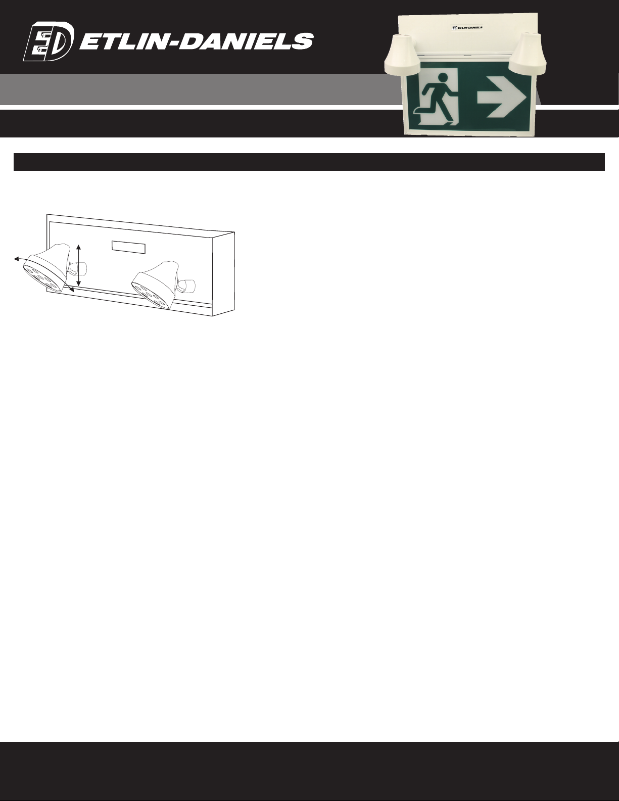
ADJUST THE LAMP HEAD
Rotation - hold the lamp head and turn it to either side.
Tilt - hold the lamp head and tilt it up or down.
INSTALLION – EC302WHM-A13-BB-GU-10RC
LED METAL RUNNING MAN EMERGENCY BATTERY UNIT WITH DUAL HEADS
OPERATION:
Self-powered (battery)
a.) To test, depress the TEST button. The charge indicator will go out and the lamps will come on.
b.) Release the TEST button. The lamp will turn off, and the charge indicator will come on.
c.) The LED indicator light indicates a high charge rate. After the battery has reached full charge. the
indicator light will go out. Under normal operation, the high charge indicator will turn on and off intermit-
tently while the unit is in standby mode.
MAINTENANCE:
1. Equipment must be tested regularly in accordance with local codes.
2. Replace the batteries as needed according to ambient conditions.
3. Clean the front cover on regular basis to provide maximum light distribution.
TROUBLESHOOTING:
THE LAMPS DO NOT LIGHT
Check the AC power supply.
AC supply is OK, and indicator light is out, replace the PC board assembly.
The pilot light is on before the test. Either the output is shorted or overloaded, or the battery is not
connected.
Battery has discharged. Allow 24 hours for recharge and then retest.
THE LAMP COME ON DIM WHEN THE BATTERY IS FIRST CONNECTED
Battery may be connected in reverse polarity. Check the connections. Connect the positive lead to the
positive battery terminal and the negative lead to the negative battery terminal. The lamps should then
turn off and the charge indicator should light up when AC power is applied.
NOTHING HAPPENS WHEN THE UNIT IS ENERGIZED
Some models have a standard time delay built into the design of the charger board. Please allow 15
minutes when the AC supply is connected at which time the LED AC-ON and CHARGE lights should
illuminate.
The unit comes with a 3 year xture and 1 year battery warranties
Table of contents
Other Etlin-Daniels Lighting Equipment manuals


Popular Lighting Equipment manuals by other brands


Lightolier
Lightolier Lytespan 8238 specification

Code 3
Code 3 21 Series Installation and operation instructions

Eaton
Eaton SURE-LITES SELA installation instructions

BARRON
BARRON EXITRONIX 400WX Series installation instructions

STERNO HOME
STERNO HOME GL33600 instructions

Brighter
Brighter 6X40W user manual


