Etlin-Daniels HBRA7 Series User manual

Turn off the power, connect AC wires. Black wire to L, white wire to N,
and green wire to GND.
Head Offi ce - 1850 Wilson Ave. · Toronto, ON · M9M 1A1 · Tel: 416.741.7336 · Fax: 416.741.9104
Toll free: in Canada. 1.800.661.9610 · in USA. 1.888.762.5384 (SOCKETS4U)
SAVE THESE INSTRUCTIONS - READ ALL INSTRUCTIONS CAREFULLY
WARNING WARNING
ATTENTION
PLEASE READ ALL INSTRUCTIONS BEFORE ATTEMPTING INSTALLATION.
• To prevent personal injury or product damage only licensed electricians/personnel should install fixture.
• To avoid electric shock or component damage disconnect power before attempting installation
or servicing.
• This product must be installed in accordance with the National Electric Code (NEC)/Canadian
Electrical Code (CEC) and all applicable Federal, State/Provincial and Local Electric Codes and
Safety Standards.
• Disconnect fixture and allow cooling prior to servicing.
• Any alteration or modification of this product is expressly forbidden as it may cause serious
personal injury, death, property damage and/or product malfunction.
• To prevent product malfunction and/or electrical shock this product must be properly grounded.
• This Round High bay will operate within the following voltage ranges: 120-347V, 50/60Hz.
• If input voltage exceeds this range, it may cause premature LED diode failure. Please ensure operation is within the
specified voltage ranges.
• Ensure ambient operating temperature between -45°C through +45°C.
•InstallingtheRoundHighbayintemperaturesoutsidetheoperatingtemperaturerangewillreducethelifeoftheRoundHighbay.
• Make sure to turn off power during all installation or maintenance processes.
IP65 Wet Location rated.
• Please keep the Round High bay away from all corrosive substances.
• To clean, please use either a damp or dry cloth.
INSTALLATION FOR HBRA7 SERIES ROUND WITH
MICROWAVE SENSOR BASE HIGH BAY
WIRING CONNECTION
HOOK MOUNT
WIRE GUARD
Lock the hook Tighten the screw. Hang up the light. Lock the screw.
REF .1 REF .2 REF .3 REF .4
SCREW HOLE
SCREW
SCREW
driver
1. Take down the 4 screws which show on the picture. 2. Lock the screws according to the picture. 3. Installation complete.
Round High Bay
Wire guard
Plastic space
r
Screw
CAN ICES-005 (B) NMB-005 (B)
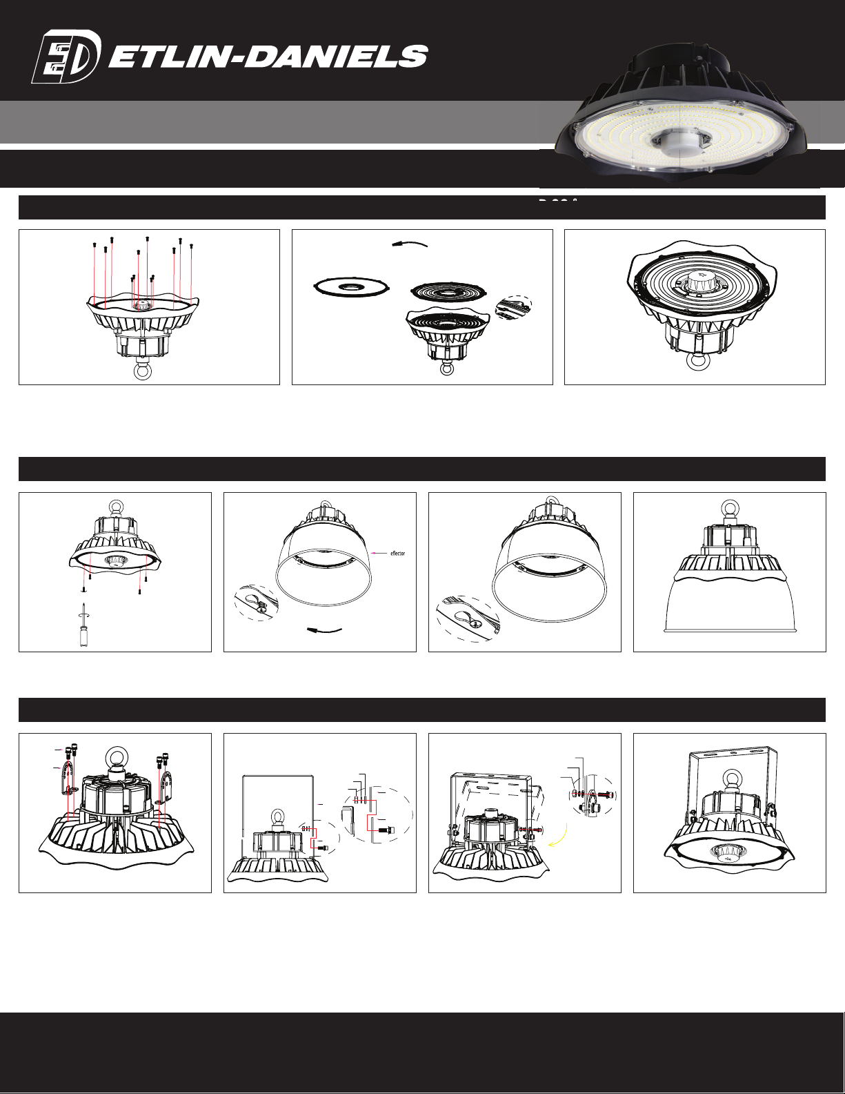
1. Unscrew the fixed screws which hold the PCB cover in place. Remove
the PCB cover.
1. Unlock the 4 screws from the PCB cover and leave
loose about 3mm.
1. Mount the 2 units of Bracket B to the back of the
fixture with screws supplied.
2. Install the Lens / Refractor over the PCB – aim the bump rectangle in
the middle of the lens / refractor to sit over the PCB boards wire entry
(shadedarea). PleasedisposeoforstorePCcoverthatcamewithfixture.
It is not to be installed over the LENS / REFRACTOR.
2. Attach the Reflector to the fixture front and turn it
clockwise to secure in place, using keyless slots.
2.Install BracketA toBracket B as per aboveimages.
3. Tighten all screws ensuring the Reflector holes are
locked in place.
3. Adjust the required angle of the bracket as per
above images and tighten screws to lock.
3. Tighten all screws. Installation is finished.
4. Installation complete.
4. Installation complete.
Head Offi ce - 1850 Wilson Ave. · Toronto, ON · M9M 1A1 · Tel: 416.741.7336 · Fax: 416.741.9104
Toll free: in Canada. 1.800.661.9610 · in USA. 1.888.762.5384 (SOCKETS4U)
SAVE THESE INSTRUCTIONS - READ ALL INSTRUCTIONS CAREFULLY
LENS / REFRACTOR INSTALLATION - 60 ˚ AND 90 ˚
ALUMINUM REFLECTOR / PC REFLECTOR INSTALLATION
YOKE MOUNT INSTALLATION
Bracket B
Screws
Bracket A
Bracket B
Bracket B
Nut
Nylon Gasket
Bracket A
Stainless Steel Gasket
Nut
Nylon Gasket
R
LENS / REFRACTOR INSTALLATION - 60 ˚ AND 90 ˚
INSTALLATION FOR HBRA7 SERIES ROUND WITH
MICROWAVE SENSOR BASE HIGH BAY

1. Unscrew the sensor cover in the direction shown (Fig 1.).
2. Screw the sensor into the bottom of the sensor to complete the installation (Fig 2. ) (Improper installation may cause waterproof failure);
3. Test Light.
On / Off
Control Detection
Area Hold
Time Daylight
Threshold Stand-by
Period Stand-by
DimmingLevel Remote Control
Setting 10-15M
High Bay
Altitude
Head Offi ce - 1850 Wilson Ave. · Toronto, ON · M9M 1A1 · Tel: 416.741.7336 · Fax: 416.741.9104
Toll free: in Canada. 1.800.661.9610 · in USA. 1.888.762.5384 (SOCKETS4U)
SAVE THESE INSTRUCTIONS - READ ALL INSTRUCTIONS CAREFULLY
SENSOR INSTALLATION
FIG .1 FIG .2
APPLICATION ENVIRONMENT.
1. Suitable only for indoor applications.
2. Not suitable for spaces where all walls are metal or with metal roofing.
3. Not to be installed in close proximity to large machinery like ventilators, ceiling fans, to avoid false triggering due to
machine vibrations.
INSTALLATION PRECAUTIONS.
1. The areas of detection cannot be shielded by metal objects.
2. Ensure the Microwave Sensor is properly secured to ensure Watertight seal.
OVERVIEW
• Automatic On / Off control with Daylight Sensor
• Optional detection range, holdtime, daylight threshold, Standby period and standby dimming level.
• Remote control settings available.
HBRA7 – INSTALLATION GUIDE MICROWAVE SENSOR
USER NOTES.
1. TheMicrowaveSensorcanpenetratewallsorglassthinnerthan20cm,andwillbeweakerifthesurfaceisthickerthan20cm.
2. The detection area will be affected by speed of motion, mounting height, and movement volume
3. The detection surface of the sensor shall be installed facing the detection area.
4. Wiring must be in accordance with the wiring diagram to avoid short circuit.
15m 5
years
INSTALLATION FOR HBRA7 SERIES ROUND WITH
MICROWAVE SENSOR BASE HIGH BAY
Head Offi ce - 1850 Wilson Ave. · Toronto, ON · M9M 1A1 · Tel: 416.741.7336 · Fax: 416.741.9104
Toll free: in Canada. 1.800.661.9610 · in USA. 1.888.762.5384 (SOCKETS4U)
SAVE THESE INSTRUCTIONS - READ ALL INSTRUCTIONS CAREFULLY
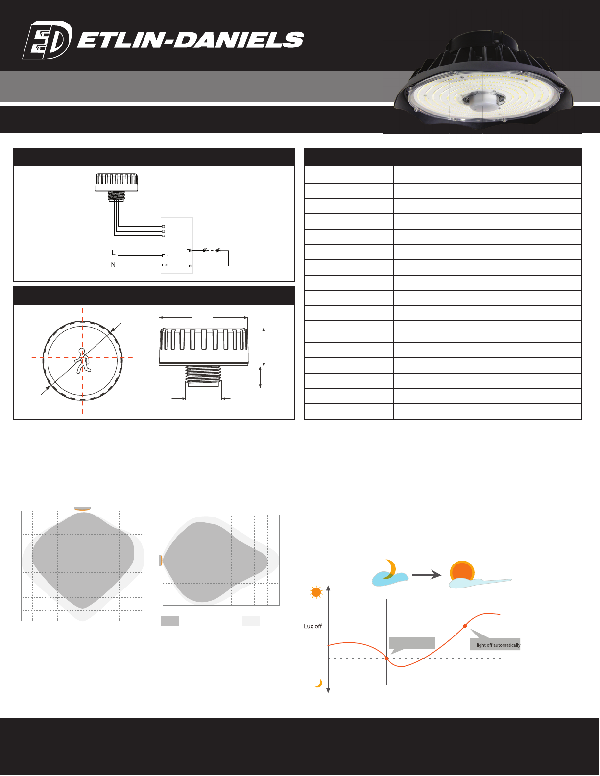
TheDusk/DawnSensor: DualPDtechnologybringsanautomaticdusk/dawnsensorthatcantell
thedifferencebetweennaturallightandLEDlight.Thisisnecessarytoensurethefixturewillbeoff
when not required. With the Daylight Priority function, it enables differentiating between artificial
light brightness, from natural light brightness, after in-fixture installation. It will automatically turn
off the fixture when ambient natural brightness exceeds the preset lux level.
Precondtion of daylight priority:
1. Standby period is +∞
2. Standby dimming level is on 10%, 20% or 30%:
3. Daylight threshold is on 30Lux, 50Lux, 80Lux or 120Lux
DAYLIGHT PRIORITY
natural light
Lux on
light on automatically
TECHNICAL INFROMATION
Operating Voltage 10-15VDC
Operating Current 30mA± 5%
Output DIM 0-10V.
Standby Power ≤0.5W.
Detection Area 25% / 50% / 75% / 100%
Hold Time 5s/30s/1 min/3 min/5 min/10 min/30 min
Daylight Threshold 2Lux / 10Lux / 30Lux / 50Lux / 80Lux / 120Lux / Disable
Standby Period 0s/10s/30s/1 min/5 min/10 min/30 min/+∞
Standby Dimming Level 10%/20%/30%/50%
Microwave Power 5.8GHz±75MHz
Mounting Height <0.3mW
Detection Range 15m / 49.2 ft (ceiling mounted)
Operating Temperature -20˚C~+60˚C
Motion Detection 0.5~1.5m/s
IP Rating IP65
Warranty 5 Years
LED Driver
Red: 12V
Grey: GND
Purple: DIM
DIM GND 12V
SENSOR WIRING DIAGRAM
DIMENSIONS (UNIT: MM)
ø50
50
24
12
22.5
DETECTION RANGE
Typical installation height 15m
Thefigureindicatesthemaximumdistanceatthehighestmountingheightwith100%sensitivity.
234 5623456
Ceiling Mounted
2
4
6
8
10
12
14
16
W all Mounted
2468 10 18161412
1
2
3
4
1
2
3
4
CoveredWell covered
INSTALLATION FOR HBRA7 SERIES ROUND WITH
MICROWAVE SENSOR BASE HIGH BAY

Hold time
Head Offi ce - 1850 Wilson Ave. · Toronto, ON · M9M 1A1 · Tel: 416.741.7336 · Fax: 416.741.9104
Toll free: in Canada. 1.800.661.9610 · in USA. 1.888.762.5384 (SOCKETS4U)
SAVE THESE INSTRUCTIONS - READ ALL INSTRUCTIONS CAREFULLY
Hold time
With sufficient Daylight, even when motion is detected, the
fixture remains off.
Fixture is on when motion is detected and off when space is vacated.
The Daylight Threshold is set to “Disable”. The fixture will be on when motion is detected. When the space is vacated, the fixture will turn off after the standby period.
After the space is vacated, the fixture will remain at 100%
brightness for the hold time
Afterthelastdetectionandthepresetholdtimehaselapsed,the
fixture turns off.
With insufficient Daylight, when motion is detected, the fixture
will turn on.
Afterthespaceisvacated,andthepresetholdtimehaselapsed,
the fixture will turn off.
AUTOMATICALLY ON / OFF FUNCTION:
NO DAYLIGHT FUNCTION
With sufficient Daylight. Even when motion is
detected, the fixture remains off.
Fixtureisautomaticallyonwhenambientlightis
lower than the preset lux level.
With insufficient Daylight, when motion is
detected, the fixture turns on.
With insufficient ambient brightness, the fixture
illuminatesto 100%whenmotion is detected.
After the space is vacated, the fixture will dim
down to the preset standby level (10%, 20%,
30% or 50%), after hold time.
The fixture dims to standby level when no mo-
tion is detected, after hold time.
Afterthestandbyperiod,the fixturewillgooff.
The fixture is off when the ambient lux level is
higher than the preset lux level.
DIMMABLE CONTROL / CORRIDOR FUNCTION
DAYLIGHT PRIORITY
When motion is detected, the sensor will turn the fixture to
100% brightness.
Standby Period
INSTALLATION FOR HBRA7 SERIES ROUND WITH
MICROWAVE SENSOR BASE HIGH BAY
Head Offi ce - 1850 Wilson Ave. · Toronto, ON · M9M 1A1 · Tel: 416.741.7336 · Fax: 416.741.9104
Toll free: in Canada. 1.800.661.9610 · in USA. 1.888.762.5384 (SOCKETS4U)
SAVE THESE INSTRUCTIONS - READ ALL INSTRUCTIONS CAREFULLY
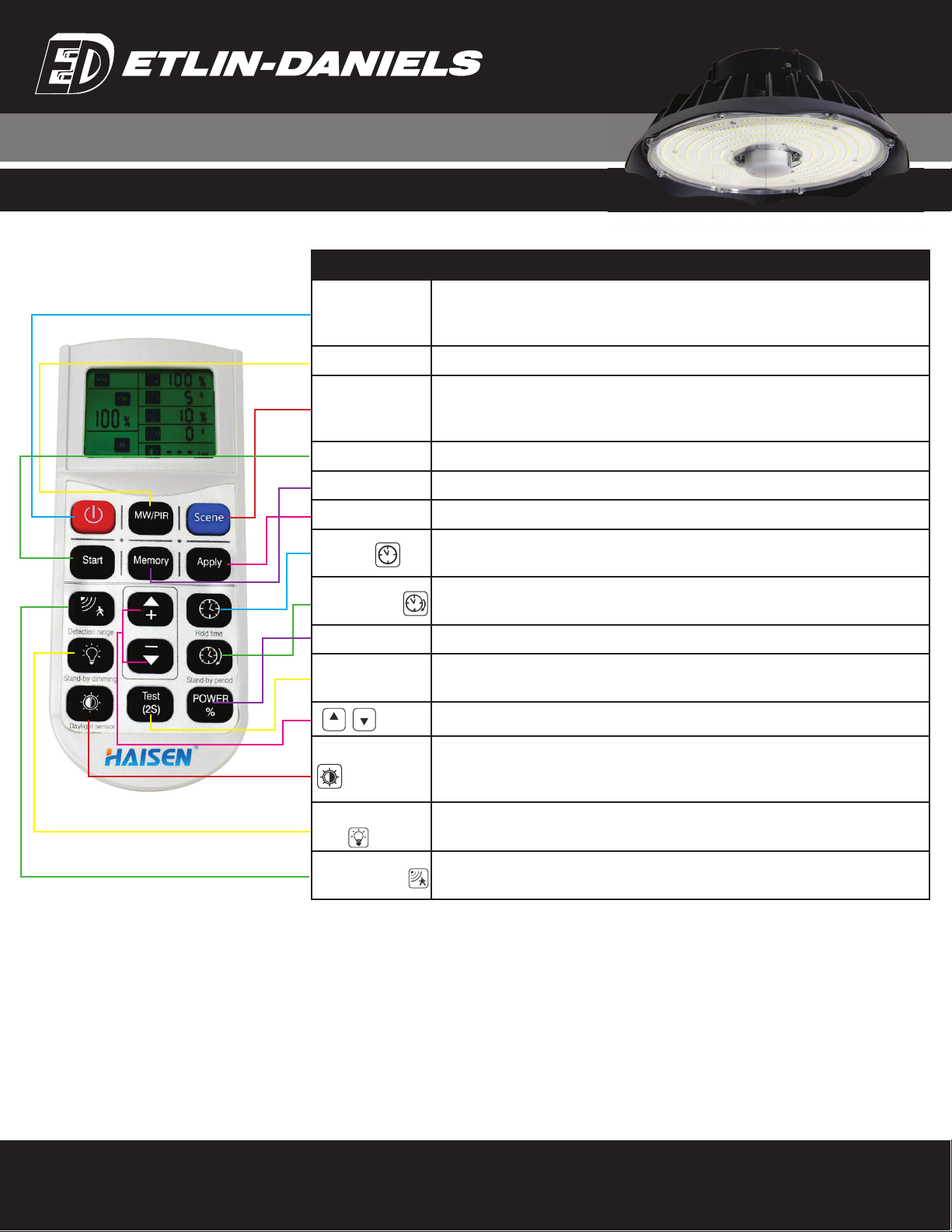
REMOTE CONTROL APPLICATIONS
BUTTON NAME DESCRIPTION
ON / OFF
1. “ON/OFF” key only functions as a switch of the light.
2. If this button is pressed to turn off the fixture before power is turned off, the fixture will
remain off after power is turned on again.
MW / PIR Change from the microwave sensor function to PIR sensor function, and the other around.
Scene
Press “Scene” button, products with DIP switch will be controlled by DIP switches;
otherwise all the setting will be just initial, that is 100% detection range, hold time 5S,
no standby time and daylight threshold disabled.
Start Start - Press the button before choosing the parameters.
Memory Memory - Press the button after choosing all the parameters to save them
Apply Apply - Press the button to deliver the saved settings to the other sensors directly
Hold Time The period of light keeping 100% brightness after moving objects leave the
detection area.
Standby Period The period of light keeping low output before it gets completely off. When it’s preset as --,
the light always keep at low output even no movement in the detection area.
Power % Press the button to change the output power from 0% to 100% it changes 5% every press.
Test (2s) The button “Test (2s)” is for testing purpose after comissioning. Pressing this button, the
sensor goes to test mode (hold time is only 2s)
Increase or decrease the parameters.
Daylight Threshold Definition of the ambient brightness; only when the ambient brightness is lower than the
preset specific lux amount, the sensor will work,; when it’s preset as “disable”, the
sensor works everytime it detects motion regardless of the ambient lux level.
Standby Dimming
Level The definition of low output during the standby period.
Detection Range The area in which movement will trigger the sensor, 100% detection area also means
strong sensitivity
MEMORY AND APPLY MODE.
1. Press the On/Off Button to turn the fixture on or off.
2. To Reset the parameters, follow steps as below:
• Press ON to turn on the fixture if it is off.
• Press START at the fixture being set.
• Press the buttons of DETECTION RANGE, HOLD TIME, STANDBY DIMMING LEVEL, STANDBY PERIOD, and DAYLIGHT
THRESHOLD one after the other in sequence. Press “+/-“ to set Parameters.Press MEMORY to memorize the settings.
NOTE: THE INTERVAL OF EACH PARAMETER SETTING SHALL BE CONTROLLED WITHIN 30 SECONDS
3. To program other fixtures in the array that will have the same program.
• Press ON to the second fixture.
• Press APPLY.
ISOLATED SETTING MODE.
1.PresstheOn/OffButtontoturn the fixtureonoroff.PressSCENE–theremotewill activatesettingsthatwere
saved last or remain at factory settings.
2. To reset the parameters, follow the steps below:
• Press ON to turn the fixture on, if it was off to start.
• Press any button of SCENE, TEST , APPLY to begin the sensor detection mode.
• PRESS the buttons of Detection Range, Hold Time, Standby Dimming Level, Standby Period and Daylight
Threshold one after the other in sequence.
NOTE:
• Setting will be saved automatically and remain until you press RESET again.
• Fixture will flicker when you are setting each parameter.
• The Icon will flash when setting the corresponding parameter.
-
+
INSTALLATION FOR HBRA7 SERIES ROUND WITH
MICROWAVE SENSOR BASE HIGH BAY
Table of contents
Other Etlin-Daniels Lighting Equipment manuals


