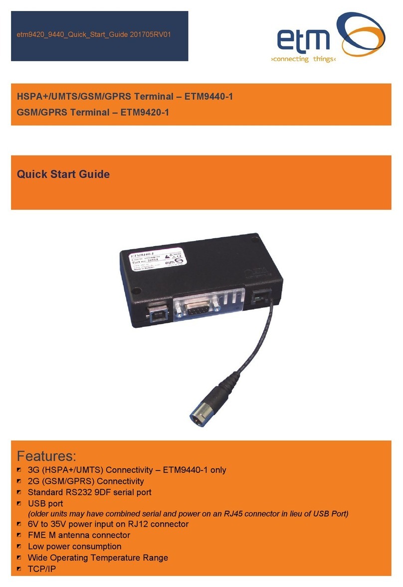
ETM ETM8140-1 User manual

UMTS/GSM/GPRS Terminal – ETM8140-1 & ETM8140-4
GSM/GPRS Terminal – ETM8120-1 & ETM8120-4
Features:
◩ 3G (UMTS) Connectivity – ETM8140-1 / ETM8140-4 only
◩ 2G (GSM/GPRS) Connectivity
◩ 4v to 35v power input
◩ Combined serial and power input on RJ45 connector
◩ 4 x I/O’s 6 pin Minibridge connector
◩ FME M antenna connector
◩ Sleep Mode for reduced power consumption
◩ User configurable via configuration tool
ETM8100 Series Quick Start GuideV002
Quick Start Guide

Page 2 of 17 For Support Contact +61-2-9956-7377
ETM8100 Series Quick Start GuideV002
Contents
Contents............................................................................................................................................ 2
Introduction ....................................................................................................................................... 3
Nomenclature ................................................................................................................................ 3
Overview. ...................................................................................................................................... 3
Applications ................................................................................................................................... 3
Power & Serial Connector, RJ45 ...................................................................................................... 4
RJ45/DB9F/Flying Lead Adaptor Cable ........................................................................................ 4
ERNI 6 Pin Minibridge I/O Connector ............................................................................................... 4
Antenna............................................................................................................................................. 5
SIM Card........................................................................................................................................... 5
SIMPin.......................................................................................................................................................5
Indicator Lights.................................................................................................................................. 6
LED indication during runtime ....................................................................................................... 6
Installation......................................................................................................................................... 7
Configuration Tool............................................................................................................................. 7
Using the Right Version of the Configuration Tool ........................................................................ 7
Using the Configuration Tool......................................................................................................... 8
Setting the Baud Rate ................................................................................................................... 9
Instructions on Setting Module Baud Rate. ................................................................................... 9
Normal/Typical Start Sequence................................................................................................... 12
Main Init Tab................................................................................................................................ 13
DefaultMode...........................................................................................................................................13
Miscellaneous..........................................................................................................................................13
SMSPolling..............................................................................................................................................13
InitAT‐CommandTable...........................................................................................................................13
ET/AT Mode.................................................................................................................................... 14
Control Via ET Commands ............................................................................................................. 14
Common ET Commands............................................................................................................. 14
CommonETCommandsContinued…......................................................................................................16

Page 3 of 17 For Support Contact +61-2-9956-7377
ETM8100 Series Quick Start GuideV002
Introduction
Nomenclature
The 2G only ETM8120 variants incorporate the Cinterion TC63i engine and are intended for
worldwide use (network and regulatory approvals permitting).
The 3G/2G ETM8140 variants incorporate the Cinterion PHS8-P engine and are intended for
worldwide use (network and regulatory approvals permitting).
Overview.
The ETM8xxx-xxx range of products are compact industrial terminals designed for M2M (Machine
to Machine) communications.
Terminal Nomenclature/History
Model Comment Module Installed
ETM8120 Variants
ETM8120-1 RJ45 socket for serial and
power connection
TC63i
ETM8120-4 RJ45 plug on approx. 120mm
cable for serial and power
connection
TC63i
ETM8130/8140 Variants
ETM8130-1 RJ45 socket for serial and
power connection
EU3-P
ETM8140-1 RJ45 socket for serial and
power connection
PHS8-P
ETM8140-4 RJ45 plug on approx. 120mm
cable for serial and power
connection
PHS8-P
Applications
Typical applications include:
◩ General M2M communications device
◩ Automated Meter Reading (Telemetry)
◩ Interface to data acquisition/data logging systems
◩ Interfacing with alarm and control applications
◩ Temperature monitoring and alarm
◩ Water metering
◩ Rainfall monitoring

Page 4 of 17 For Support Contact +61-2-9956-7377
ETM8100 Series Quick Start GuideV002
Power & Serial Connector, RJ45
The ETM8xxx-xxx modems utilise a single RJ45 socket (or plug for -4 versions) for connection of
serial interface and power.
The RS232 Port is the primary interface for the application software and connection to external
devices. ET/AT commands are used to communicate with the terminal.
Pin Function Looking at Modem Socket
ETM8xxx-1
Looking at RJ45 Plug
ETM8xxx-4 (Hook underneath)
1 Power Supply
(+4 to +35VDC)
12345678
12345678
2 DCD
3 DTR
4 GND
5 RX
6 TX
7 CTS
8 RTS
RJ45/DB9F/Flying Lead Adaptor Cable
The following adaptor cable is available from ETM for ease of connection to the modem when
programming and testing.
Adaptor Cable for Programming ETM8xxx-xxx Modems
White/red positive +4 to 35VDC blue/black Negative/Gnd
ERNI 6 Pin Minibridge I/O Connector (if fitted)
If fitted 4 x I/O’s configurable as digital, analogue or pulse are available on the ERNI 6 Pin
Minibridge IO connector, pin allocations are as shown below.
Pin Function Looking at Modem Socket
1 to 4 Configurable as:
◩ Digital Input: LL<0.5V, HL>2.5V, Max Input 50VDC
◩ Digital Output: LL0V, HL3V,0.1mA
◩ Pulse Input (I/O9): LL<0.5V, HL>2.5V, Max Input 50VDC
◩ Analogue Input: 0-2.5VDC, Max Input 50VDC
ERNI 1.27mm Minibridge
Connector
5 & 6
GND
Caution
This modem has no reverse polarity protection on the power input, incorrect
connection of power may damage the modem
1 2 3 4 5 6

Page 5 of 17 For Support Contact +61-2-9956-7377
ETM8100 Series Quick Start GuideV002
Antenna
The ETM8xxx-xxx Terminal has a standard FME M antenna Plug on the end of an approximately
120mm cable.
FME M Antenna Connector
SIM Card
The SIM card connector is located on the underside of the ETM8xxx-xxx Terminal. The unit
supports both 3V or 1.8V SIMs. Any SIM card used needs to be correctly provisioned for the
services and network upon which it is intended to be used.
If the terminal is intended to be used for remote access to a device a terminating data number for
Circuit Switch Data (CSD) MAY need to be provisioned by the network operator, this number will
usually differ from any voice/SMS number, eg for Telstra;
◩ Telstra NextG® SIMs when used for CSD requires 2620 bearer capability
SIM Pin
If the SIM used has a PIN either;
The unit can be configured to enter the SIM pin, refer configuration tool section
OR
The SIM PIN should be deactivated, insert the SIM in a mobile phone and deactivate then
transfer the SIM into the ETM8xxx-xxx unit.
Caution
Always disconnect power supply before
inserting or removing SIM Card.
Care should be taken in inserting and
removing the SIM card so as not to
dama
g
e the SIM holder or cover.

Page 6 of 17 For Support Contact +61-2-9956-7377
ETM8100 Series Quick Start GuideV002
Indicator Lights
LED indication during runtime
BLUE Status 1 LED signal from the Module. LED is flashing when the ME is registered to the network
and either awake or in power saving state.
YELLOW Busy with communication and waiting for answer from the Module. Socket Established
indication.
GREEN Status 0 LED signal from the Module. LED is flashing when the ME is registered to the network
and either awake or in power saving state.
BLUE LED mode (UMTS) Function
500ms On / 500ms Off Limited Network Service: No SIM card inserted or no PIN entered, or network
search in progress, or ongoing user authentication, or network login in
progress.
40ms on / 3990ms off LED flashes when the ME is registered to the UMTS network and either awake
or in power saving state.
Off ME is not registered to the UMTS network.
75ms on / 75ms off /
75ms on /1990ms off
One or more UMTS PDP contexts activated.
YELLOW LED mode Function
Flashing Busy with communication with the Module.
0.5s On / 0.5s Off Waiting for answer from the Module.
On When connected to an ISP and a Socket is established.
GREEN LED mode (GSM) Function
600ms On / 600ms Off Limited Network Service: No SIM card inserted or no PIN entered, or
network search in progress, or ongoing user authentication, or network
login in progress.
75ms on / 3s off IDLE mode: The mobile is registered to the GSM network (monitoring
control channels and user interactions). No call is in progress.
75ms on / 75ms off /
75ms on /3s off
One or more GPRS PDP contexts activated.
500 ms on / 50 ms off Packet switched data transfer is in progress.
Off ME is in one of the following modes:
- POWER DOWN mode
- AIRPLANE mode
- CHARGE ONLY mode
- NON-CYCLIC SLEEP mode
- CYCLIC SLEEP mode with no temporary wake-up event in progress
On Depending on type of call:
Voice call: Connected to remote party.
Data call: Connected to remote party or
exchange of parameters while setting
up or disconnecting a call.
BLUE YELLOW GREEN
ETM8100 STATUS LEDs
UMTS MCU Status GSM

Page 7 of 17 For Support Contact +61-2-9956-7377
ETM8100 Series Quick Start GuideV002
Installation
1. Connect an RS232 serial cable between the ETM8xxx-xxx terminal and the external device
or PC (a Serial/USB Adapter may be used if your computer does not have a serial port,
also ETM stocks an RJ45/DB9F adaptor cable with flying lead for power)
2. Fit a suitable antenna to the ETM8xxx-xxx unit.
3. Install a SIM card enabled for the services you intend to use. If the terminal is intended to
be used for remote access to a device a terminating data number for Circuit Switch Data
(CSD) will need to be provisioned by the network operator, this number will usually differ
from any voice/SMS number. Note that for Telstra you will need to request;
◩ 2620 bearer capability (Telstra NextG™ Sims)
4. Connect the power supply. (The unit accepts a broad range of voltages from +4 to +35VDC,
take care the unit does not have any reverse polarity protection)
5. Refer to the following information or contact ETM for instructions on configuring the unit for
the intended application.
Configuration Tool
Using the Right Version of the Configuration Tool
When the unit starts up and is connected to a terminal window and Escape is pressed (see below)
the version of the configuration tool will be shown as follows, check you have the correct
configuration tool for the unit – if you do not then contact ETM and request the appropriate version
or visit the support section of ETM’s website.
In this example the
appropriate
configuration tool is
CT0101
Caution
Do not try to program/configure a
unit with the wrong version of the
configuration tool.

Page 8 of 17 For Support Contact +61-2-9956-7377
ETM8100 Series Quick Start GuideV002
Using the Configuration Tool
When you power up the wireless modem to do any configuration you MUST follow these steps if
you are unfamiliar with the operation of the Configuration Tool:
1. Start the configuration tool.
2. Chose the correct communications port ( using the Set COM Port button to select a port other
than the one chosen by the Configuration Tool ) – ensure the port is set for a baud rate of
9600 (it must be at this speed to be programmed in ESC mode).
3. Confirm that the port opens (the indicator MUST show ‘OPEN’ for your chosen port).
4. Click on the Terminal Tab.
5. Click into the black terminal window so that you see a flashing white cursor.
6. Power up the wireless modem - remember to plug the power into the correct socket, it is the
one next to the antenna lead, plugging the power connector into the I/O connector can
damage it, if this happens you may need to return the wireless modem for repair.
7. Immediately after powering up the modem press the ESC key on the keyboard, you should
only need to press it 3 or 4 times, after a short period you should see an ‘Escape Pressed’
message from the wireless modem – if you don’t and instead you see a ‘MS:^SYSSTART’
message then repeat the process again. Without the ‘Escape Pressed’ message being
displayed you CANNOT perform any configuration on the wireless modem (while it is
possible to use the Configuration Tool once the wireless modem has fully started up this may
not be possible if the wireless modem has not yet been fully configured).
8. NOTE: You can also check ‘Send <ESC> on SYSTEM START’ (the Configuration Tool to will
automatically send an ESC character when it sees the SYSTEM START message) in the
bottom right hand corner of the Configuration Tool (but this doesn’t work with some USB to
Serial adapters) – if you check this remember to uncheck it again when you restart the
modem after any programming changes, otherwise you may inadvertently leave the modem
in programming mode rather than run mode.
9. You are now ready to use the configuration tool to make changes to the wireless modem.
10. Once you are familiar with the Configuration Tool you can shorten the procedure, if the
wireless modem is already live/working, by simply reading and writing the configuration
without restarting the wireless modem and pressing the ESC key. Note if any changes are
made to the modem you should power cycle or software reset (ET&SR) the modem to ensure
that any new mode of operation ( based on your configuration changes ) comes into effect. If
you make no changes, only reading the configuration, you do not need to restart the modem.
11. Settings can be saved to a file on your PC. If you need to configure another ETM8xxx-xxx
with the same settings this file can be loaded into the configuration tool and written to any
additional units that require the same settings.

Page 9 of 17 For Support Contact +61-2-9956-7377
ETM8100 Series Quick Start GuideV002
Setting the Baud Rate
The baud rate for the ETM8xxx-xxx can be set in the settings tab of the configuration tool as below.
As default the unit is set to a baud rate of 9600.
The baud rate of the ETM8xxx-xxx modem needs to be set as above with both the
UMTS/GPRS<>Module and MCU<>Port Settings being the same plus the internal engine/module
(TC63i/PHS8-P) must be set to the same baud rate using AT+IPR command. After making setting
changes remember to write to the unit.
Instructions on Setting Module Baud Rate.
1. Change to AT Mode using the ETSC1 command, this can be sent using the drop down box on
the bottom left or by typing into the terminal window
Common ET
commands can be
found and sent from
here

Page 10 of 17 For Support Contact +61-2-9956-7377
ETM8100 Series Quick Start GuideV002
2. Set the baud rate using the at+ipr=xxxx command, where xxxx is the desired baud rate, note
this speed setting will need to match the settings under the “Settings”tab.
Note the Com Port will need to be set to the current module baud rate for the command to be
accepted.
3. Send --- to return to command mode (you must have the Com Port at 9600 baud rate for the ---
to be successful) and continue programming the unit.

Page 11 of 17 For Support Contact +61-2-9956-7377
ETM8100 Series Quick Start GuideV002
If the baud rate set in the settings tab does not match the modules baud rate then an error similar
to that shown below on start-up will occur, when the unit is started in run mode.
To solve the above problem wait until the ETM9910 SYSTEM START message appears and press
the ESC key to put the unit into escape mode for programming, if successful the screen should
look as follows.
Now follow the procedure on the previous page to set the baud rate correctly, make sure it
matches the baud rates set in the “Settings” tab.
Press ESC at this
point, or have “Send
<ESC> on System
Start” box ticked

Page 12 of 17 For Support Contact +61-2-9956-7377
ETM8100 Series Quick Start GuideV002
Normal/Typical Start Sequence
Upon re-starting the modem, with the port set to the correct speed, you should see the following
typical start-up sequence, this sequence may vary depending actual unit settings.

Page 13 of 17 For Support Contact +61-2-9956-7377
ETM8100 Series Quick Start GuideV002
Main Init Tab
The above screen shot shows the default configuration of the unit set to ET Command mode,
some of the settings are described below for more details refer to the Configuration Tool Userguide.
Default Mode
When the unit powers up it can start in 3 modes
ET Mode - standard operating mode
AT Mode - the unit behaves like a standard GSM/UMTS wireless modem where the user controls
the internal cellular module directly without using the MCU. – For further assistance on using the
ETM9xxx-xxx as an AT modem please contact ETM.
GPS-capture Mode - data coming from a GPS connected to the serial interface is stored in the unit.
Miscellaneous
Switch to ET-mode locally when CD is active - The unit will operate in ET command mode
whenever a dial in connection is active - useful for programming the unit over a dial up connection.
NOTE: Incoming CSD calls are only possible on UMTS/WCDMA when the modem does not have
an IP Address allocated (is not connected to the internet).
Do SIM PIN Check at Startup - If this is checked, which it is the default configuration, the modem
will check to see if the SIM PIN is required and if it is the SIM PIN as entered will be sent to the
module.
If this option is unchecked then the modem will not check the SIM PIN nor will it send any of the
commands listed in the AT-Command list – refer to Configuration Tool Userguide for further details.
SMS Polling
Both ‘Read SMS Memory’ options should generally be checked, though the lower checkbox will
generally be greyed out.
Init AT-Command Table
Here you may set various initialisation commands that are executed at power up.
Caution
Do not uncheck the “Do SIM Pin
Check at startup”item unless you
are certain this setting is
applicable.
In typical operation the unit needs
this setting to be active to correctly
initialise the module, even if the
SIM has had its PIN deactivated

Page 14 of 17 For Support Contact +61-2-9956-7377
ETM8100 Series Quick Start GuideV002
ET/AT Mode
This unit is designed to be able to operate in dual ET/AT mode, which commands are accepted in
each mode are defined below.
Mode ET Commands AT Commands
ESC (programming mode) Yes No
The units’ processor responds with an
OK however the commands are not
actually performed
ET Mode Yes
Module Direct (AT Mode) Yes Yes
Control Via ET Commands
As default the ETM8xxx-xxx is set to ET Command Mode, ET Commands are specific to ETM
terminals and allow for control, configuration and information requests to be sent to and from the
terminal. In ETM command mode AT commands cannot be sent to the unit.
ET commands can be sent via SMS or from configuration tool when directly connected or via an IP
or CSD connection. It is recommended that more complex settings such as changing messages or
phone numbers are made using the configuration tool.
Common ET commands are shown on the next two pages, for a full ET command list contact ETM.
Common ET Commands
Ref Command Command Format Action/Request/
Notes
Typical Response/Notes
1 ETM8xxx-xxx
information
ETI Send ETM9xxx-
xxx information
ID:”ID string”
RTC: – Real Time Clock (Date and Time)
REFDATE: – Reference date, Day
counter
TOTAL: – Total time since start
RSTIN: – Time to SW reset
RC SW: PU: – Reset counter SW /
Power Up
SW#: – Software number
HW#: – 95*Hardware number (96* if
ETM9600)
SIGNAL: n MIN: MAX: – Signal strength
real / min / max
SUPPL VOLT: – Supply voltage( V )
CHAN: RS: dBm: LAC: CELL: – Cell
information
MTemp: – Module Temperature(degC)
CID: – Configuration ID
2 Software
Reset MCU
System
ET&SR May be useful if
it is suspected
the unit has
locked up or
communications
between modem
and external
device have
stalled
3 Show I/O
settings
ETRIS Show
status/value of
each I/O
1:DI,1,2:DI,1,3:DI,1,4:DI,1
I/O 1 Digital Input = 1, I/O 2 Digital Input =
1,…

Page 15 of 17 For Support Contact +61-2-9956-7377
ETM8100 Series Quick Start GuideV002

Page 16 of 17 For Support Contact +61-2-9956-7377
ETM8100 Series Quick Start GuideV002
Common ET Commands Continued…
Ref Command Command Format Action/Request/
Notes
Typical Response/Notes
4 Read A/D
input
ETRAIX Where X is AI
No., eg:
ETRAI3 reads
analogue input 3
If configured for scaled values, will return
scaled value otherwise raw voltage input
5 Read all A/D
inputs
ETRAIA Reads all
analogue inputs
6 Set IO pin
selection to
digital I/O, set
direction to
Output and
Set pin level
ETS(X:DO=0) Sets I/O No X to
low, (change 0
to1 to set to
high)
Low DO status is <0.5V 0.1mA, High DO
Status is >2.5V 0.1mA. External Circuitry
capable of detecting these signals is
required to switch external devices
ON/OFF.
7 Set IO pin
selection to
digital I/O, set
direction to
Output and
Set pin level
for a specified
time period
ETS(X:DO=0)TAY Sets I/O No X to
low for Y
seconds then
reverts to High
Y is in whole minutes
8 Set IO pin
selection to
analogue I/O,
set direction to
Input
ETS(X:AI) Sets I/O Pin X to
Analogue Input
9 Set IO pin
selection to
digital I/O, set
direction to
Input
ETS(X:DI) Sets I/O Pin X to
Digital Input
10 Set SMS
Alarm Phone
Numbers
ET-
SSP=Phnumber1 ,
Phnumber2,….,Phn
umber5
Sets phone
numbers in
phone book
All numbers must be entered, if less than
5 numbers enter ,’s with no spaces
between until all 5 slots are completed eg
ET-SSP=XXXXXXXXXX,,,,
Note you cannot add/or remove phone
numbers to the unit in this manner as the
unit will not necessarily have the correct
corresponding entry in the individual I/O
settings.
Only use to change existing phone list, so
if three number in an already existing list
then replace with 3 numbers
11 Sends one AT
Command to
the module
ETSEND=AT… Sends a single
AT command to
the module

ETM Matteknik AB
Ekbacksvägen 32
SE-168 69 Bromma
Sweden
Tel: +46 (0)8 25 28 75
Fax: +46 (0)8 80 11 10
Email: [email protected]
Web: www.etm.se
ETM Pacific Pty Ltd
LGF, 275 Alfred Street
North Sydney NSW 2060
Australia
Tel: +61 (0)2 9956 7377
Fax: +61 (0)2 9956 5791
Email: info@etmpacific.com.au
Web: www.etmpacific.com.au
© ETM Pacific Pty Ltd · Subject to change without notice.
This manual suits for next models
4
Table of contents
Other ETM Touch Terminal manuals


