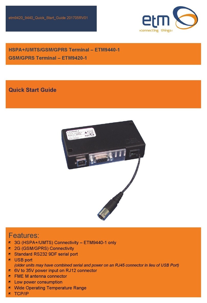
ETM ETM9900(J) User manual

Features:
◩ 3G (Tri-band HSDPA/UMTS) Connectivity
◩ Standard RS232 9DF serial port
◩ 6v to 35v power input on RJ12 connector
◩ 4(or 7) x digital, analogue or pulse I/O’s on RJ45 connector
◩ SMA M antenna connector
◩ Sleep Mode for reduced power consumption
Issue 27012009
Cinterion
HC25(HC28) Inside
ETM9900(J)
Quick Start Guide
HSDPA/UMTS/GSM/GPRS Terminal

Page 2 of 16
ETM9900(J) Quick Start Guide Issue 27012009
Contents
Introduction....................................................................................................................................... 4
Nomenclature................................................................................................................................ 4
Overview. ...................................................................................................................................... 4
Applications................................................................................................................................... 4
Interfaces....................................................................................................................................... 4
Power Supply.................................................................................................................................... 5
RJ45 I/O Connector.......................................................................................................................... 5
Serial (RS232) Port........................................................................................................................... 6
Antenna............................................................................................................................................. 6
3V SIM Card ..................................................................................................................................... 6
Indicator Lights.................................................................................................................................. 7
Installation......................................................................................................................................... 8
Configuration Tool............................................................................................................................. 8
Introduction.................................................................................................................................... 8
Using the Right Version of the Configuration Tool........................................................................ 8
Using the Configuration Tool......................................................................................................... 8
Modem Initialisation Settings - Main Init Tab............................................................................... 10
Control Via ET Commands............................................................................................................. 10
Dry contact generated SMS alarm.................................................................................................. 12
Example ...................................................................................................................................... 12
Wiring Diagram............................................................................................................................ 12
Configuration Tool Settings......................................................................................................... 12
Temperature Alarm......................................................................................................................... 14
Example ...................................................................................................................................... 14
Wiring Diagram............................................................................................................................ 14
Configuration Tool Settings......................................................................................................... 14

Page 3 of 16
ETM9900(J) Quick Start Guide Issue 27012009

Page 4 of 16
ETM9900(J) Quick Start Guide Issue 27012009
Introduction
Nomenclature
ETM9900 incorporates the Siemens HC25 engine and is intended for use within Australia, NZ and
worldwide.
The ETM9900J variant incorporates the Siemens HC28 engine and is intended for use within
Japan on the Softbank network and global roaming.
Overview.
The ETM9900(J) is an industrial terminal designed for M2M (Machine to Machine) communications.
With Tri-band UMTS/HSDPA and Quad-Band GSM/GPRS/EDGE capability, the ETM9900(J) has
the versatility to operate on virtually any GSM or UMTS network.
Terminal Nomenclature/History
Model Comment Module Installed
ETM9900 First Release HC25 Release 1.0, 1.2, 1.78 or
2.05
ETM9900-1 Future Release HC25 Release 2.05, 7 x I/O’s
versus 4 x I/O’s for ETM9900
ETM9900J First Release Japan only unit HC28, 7 x I/O’s
Module Nomenclature/History
Model Comment
HC25 Release 1.0/1.2 Initial release
HC25 Release 1.78 Maintenance Release Australia and New Zealand Only
HC25 Release 2.05 Current Release
HC28 Release 1.03 Current Release
Applications
Typical applications include:
◩ Security;
◩ Automated Meter Reading (Telemetry);
◩ Interface to data acquisition/data logging systems;
◩ Broadcasting/updating multi-media files;
◩ Interfacing with alarm and control applications.
Interfaces
◩ RJ12 power connector
◩ RJ45 I/O connector
◩ RS232 interface (V.24/V.28 on the D-Sub socket)
◩ Antenna connector SMA Jack (female)
◩ Mini-SIM card holder

Page 5 of 16
ETM9900(J) Quick Start Guide Issue 27012009
Power Supply
The ETM9900(J) power connection is a 6 pin RJ12 connector, pin allocations are shown below.
Pin Function
1 Power Supply (+6 to +35VDC)
2 Not Used
3 Not Used
4 Not Used
5 Not Used
6 GND
RJ45 I/O Connector
4 x I/O’s configurable as digital, analogue or pulse are available on the RJ45 connector, pin
allocations are as shown below.
Pin Function
1 Configurable as:
◩ Digital Input: LL<0.5V, HL>2.5V, Max Input ±50VDC
◩ Digital Output: LL0V/0.1mA, HL3V,0.1mA
◩ Pulse Input: LL<0.5V, HL>2.5V, Max Input ±50VDC
2 Configurable as:
◩ Digital Input: LL<0.5V, HL>2.5V, Max Input ±50VDC
◩ Digital Output: LL0V/0.1mA, HL3V,0.1mA
3 Configurable as:
◩ Digital Input: LL<0.5V, HL>2.5V, Max Input ±50VDC
◩ Digital Output: LL0V/0.1mA, HL3V,0.1mA
◩ Analogue Input: 0-2.5VDC
4 Configurable as:
◩ Digital Input: LL<0.5V, HL>2.5V, Max Input ±50VDC
◩ Digital Output: LL0V/0.1mA, HL3V,0.1mA
◩ Analogue Input: 0-2.5VDC
5 Configurable as:
◩ Digital Input: LL<0.5V, HL>2.5V, Max Input ±50VDC
◩ Digital Output: LL0V/0.1mA, HL3V,0.1mA
◩ Analogue Input: 0-2.5VDC
6 Configurable as:
◩ Digital Input: LL<0.5V, HL>2.5V, Max Input ±50VDC
◩ Digital Output: LL0V/0.1mA, HL3V,0.1mA
◩ Analogue Input: 0-2.5VDC
7 Configurable as:
◩ Digital Input: LL<0.5V, HL>2.5V, Max Input ±50VDC
◩ Digital Output: LL0V/0.1mA, HL3V,0.1mA
◩ Analogue Input: 0-2.5VDC
8 GND
Caution
Take care to ensure that only the
correct connectors are used or
mechanical damage to the pins may
result.
I/O’s 5 thru 7 not
available on
ETM9900 Version 1

Page 6 of 16
ETM9900(J) Quick Start Guide Issue 27012009
Serial (RS232) Port
The RS232 Port is the primary interface for the application software and connection to external
devices. AT commands are used to communicate with the terminal. The RS232 interface is
implemented as a 9-pin D-Sub socket with screw fittings.
Pin Function
1 DCD Out
2 RXD Out
3 TXD In
4 DTR In
5 GND
6 DSR Out
7 RTS In
8 CTS Out
9 RING Out
Antenna
The ETM9900(J) Terminal has a standard SMA Jack (Female) antenna Plug on the end of an
approximately 90mm cable.
3V SIM Card
The SIM card connector is located at the rear of the ETM9900(J) Terminal. Any SIM card used
needs to be correctly provisioned for the services and network upon which it is intended to be
used .
SMA Connector
Caution
Always disconnect power supply
before inserting or removing SIM
Card.
Care should be taken in inserting
and removing the SIM card so as
not to damage the SIMholder or
cover.

Page 7 of 16
ETM9900(J) Quick Start Guide Issue 27012009
Indicator Lights
Blue/RedLED
(UMTS)
Function
Flashing LED flashes when the ME is registered to the UMTS network and either
awake or in power saving state.
While the STATUS1 (BLUE/RED) signal is active the STATUS0 (GREEN)
signal is inactive.
Off ME is not registered to the UMTS network.
YELLOW LED
(MCU)
Function
Flashing Communicating with the module HC25(HC28).
500ms On / 500ms
Off Waiting for Answer from Module HC25(HC28).
On When connected to an ISP and a Socket is established.
GREEN LED
(GSM)
Function
500ms On / 500ms
Off
Flashes at 1Hz and 50% duty cycle when the ME is awake and not registered
to any network.
2s On / 2s Off Flashes at 0.25 Hz and appr. 50% duty cycle when the ME is in power saving
state and not registered to any network. When the ME is in power saving
state and not registered, the flashing frequency may be less than 0.25Hz and
the duty cycle may vary, for example between 45% and 55%. These
variations are due to transitions from awake state to power saving state
which may occur at the beginning of an LED flashing period (eg. at the
beginning of a 1Hz or 0.25Hz flashing period). In the worst case, the LED will
indicate a transition from awake to power saving after 4s.
Flashing LED flashes when the ME is registered to the GSM network and either awake
or in power saving state.
While the STATUS0 signal is active the STATUS1 signal is inactive.
Off ME is not registered to the GSM network.
RED
UMTS YELLOW
MCU Status Green
GSM
ETM9900 Status LEDs
RED
UMTS YELLOW
MCU Status Green
GSM
ETM9900-1/9900J Status LEDs

Page 8 of 16
ETM9900(J) Quick Start Guide Issue 27012009
Installation
1. Connect a standard RS232 modem cable 9DF to 9DM between the ETM9900(J) Terminal
and the external device or PC (a Serial/USB Adapter may be used if you computer does not
have a serial port).
2. Fit a suitable antenna to the ETM9900(J) unit.
3. Install a SIM card for enabled for the services you intend to use. If the terminal is intended
to be used for remote access to a device a terminating data number for Circuit Switch Data
(CSD) will need to be provisioned by the network operator, this number will usually differ
from any voice/SMS number. Note that for Telstra you will need to request;
◩ 2620 bearer capability (Telstra NextG™ Sims)
4. Connect the power supply. (The unit accepts a broad range of voltages from +6 to
+35VDC)
5. Refer the Common AT Commands section for recommended AT settings for the following
applications;
◩ SMS
◩ Circuit Switch Data
6. Refer to page 8 for instructions on configuring the unit for the intended application, SMS
alarm, IP connectivity etc.
Configuration Tool
Introduction
The HC25/HC28 engine used in the ETM9900(J) does not support storing of an active profile. A
configuration tool for the modem is available (FOC) upon request, that can be used to ensure that
a specified set of AT commands are always initialized at start-up.
Using the Right Version of the Configuration Tool
When the unit starts up and is connected to a terminal window and Escape is pressed (see below)
the version of the configuration tool will be shown as follows, check you have the correct
configuration tool for the unit – if you do not then download the correct one see page 3 for access
to downloads.
Using the Configuration Tool
It is recommended that you save the configuration tool on the computer you are using to configure
the ETM9900(J).
1. Start the Configuration Tool and go to the Terminal Tab on the screen.
2. Go to the Set Com Port Tab and select the Serial Port which will be used for the ETM9900(J).
3. Ensure the Port is open, click TAB to open if required
In this example the
appropriate
configuration tool is
CT03.00

Page 9 of 16
ETM9900(J) Quick Start Guide Issue 27012009
4. Place curser in the black area of the terminal window and click mouse to ensure the terminal
window is active.
5. Connect the ETM9900(J) to your computer using the serial cable.
6. Connect the power to the ETM9900(J) and repeatedly (usually three times) depress the ESC
key on your computer.
If successful the following message appears:
Escape Pressed
>
If unsuccessful repeat step 6.
Pressing escape disconnects the module and assists in Reading from or Writing to the unit.
7. Click on the Read EE Tab (Blue Arrow) to read current configuration. If first attempt to read is
unsuccessful, repeat.
8. Use the Main Init, Settings, Alarm / Message, I/O or other Tabs to enter required settings.
9. After you have re-configured the unit you need to write the commands to the terminal’s
EEPROM by pressing the Red arrow. If first attempt to read is unsuccessful, repeat.
10. Settings can be saved to a file on your PC. If you need to configure another ETM9900(J) with
the same settings this file can be loaded into the configuration tool and written to any
additional units that require the same settings.
The following configuration examples are provided in the following sections;
◩ Dry contact generated SMS alarm
◩ Temperature Alarm

Page 10 of 16
ETM9900(J) Quick Start Guide Issue 27012009
Modem Initialisation Settings - Main Init Tab
Modem AT Initialisation settings can be sent to the modem using the Main Init Tab.
AT^SCFG=“Radio/Band”,”X” (where X=band)
X=1, GSM 900MHz
X=2, GSM 1800MHz
X=16, WCDMA 2100MHz
X=64, WCDMA 850MHz (NextG™)
X=65, GSM 900MHz & WCDMA 850MHz
X=80, WCDMA 850/2100MHz
X=127, Default setting all bands
ATS0=2 Will set the unit to answer an incoming call after 2 rings, and may be useful for
applications using a Circuit Switch Data Call.
Control Via ET Commands
As default the ETM9900(J) is set to ET Command Mode, ET Commands are specific to ETM
terminals and allow for control, configuration and information requests to be sent to and from the
terminal. In ETM command mode AT commands cannot be sent to the unit.
ET commands can be sent via SMS or from configuration tool when directly connected or via an IP
or CSD connection. It is recommended that more complex settings such as changing messages or
phone numbers are made using the configuration tool.
Common ET commands are shown below, for a full ET command list download the relevant
documents from Docbanq (see page 3).

Page 11 of 16
ETM9900(J) Quick Start Guide Issue 27012009
Command Command
Format Action/Request/Notes Typical Response
ETM9900
information ETI Send ETM9900
information ID:”ID string”
RTC: – Real Time Clock (Date and Time)
REFDATE: – Reference date, Day counter
TOTAL: – Total time since start
RSTIN: – Time to SW reset
RC SW: PU: – Reset counter SW / Power Up
SW#: – Software number
HW#: – 95*Hardware number (96* if
ETM9600)
SIGNAL: n MIN: MAX: – Signal strength real /
min / max
SUPPL VOLT: – Supply voltage( V )
CHAN: RS: dBm: LAC: CELL: – Cell
information
MTemp: – Module Temperature(degC)
CID: – Configuration ID
Check Voltage
Level ETRVL Indicate supply
voltage to ETM9900
Software Reset
MCU System ET&SR May be useful if it is
suspected the unit
has locked up or
communications
between modem and
external device have
stalled
Show I/O
settings ETRIS Show status/value of
each I/O 1:DI,1,2:DI,1,3:DI,1,4:DI,1,5:DI,1,6:DI,1,7:DI,1,
I/O 1 Digital Input = 1, I/O 2 Digital Input =
1,…
Read A/D input ETRAIX Where X is AI No.,
eg:
ETRAI3 reads
analogue input 3
If configured for scaled values, will return
scaled value otherwise raw voltage input
Read all A/D
inputs ETRAIA Reads all analogue
inputs
Set IO pin
selection to
digital I/O, set
direction to
Output and Set
pin level
ETS(X:DO=0) Sets I/O No X to low,
(change 0 to1 to set
to high)
Low DO status is <0.5V 0.1mA, High DO
Status is >2.5V 0.1mA. External Circuitry
capable of detecting these signals is required
to switch external devices ON/OFF.
Set IO pin
selection to
analogue I/O,
set direction to
Input
ETS(X:AI) Sets I/O Pin X to
Analogue Input
Set IO pin
selection to
digital I/O, set
direction to
Input
ETS(X:DI) Sets I/O Pin X to
Digital Input

Page 12 of 16
ETM9900(J) Quick Start Guide Issue 27012009
Dry contact generated SMS alarm
One or more of the four I/O’s can be used to generate an SMS alarm message from the
ETM9900(J) unit. Typical applications include;
◩ Security, reed switch on a door/window or alarm relay from a security panel
◩ Tank low/high level alarm
◩ Flow switch alarm to warn if flow is lost in a pumping system
◩ Alarm relay from a machine, such as a refrigeration unit
Example
Assume an alarm message is required to be sent to two phone numbers when a tank level drops
below a pre-determined point.
Wiring Diagram
Configuration Tool Settings
1. Enter Phone Numbers and Unit ID in Alarm Message Tab
1 2 3 4 5 6 7 8
RJ45 I/O Connector
Normally closed level switch
opens when tank level drops
1 2 3 4 5 6
+ -
+6 to +35VDC
Power Supply
RJ12 Power
Connector

Page 13 of 16
ETM9900(J) Quick Start Guide Issue 27012009
2. Set I/O1 as Digital Low to High (NC), the message Tank Level Low will be sent to each
phone number when I/O1 changes from closed to open circuit
Note:
1. Delay before alarm is activated is recommended to reduce the incidence of multiple SMS
being sent in the event of chattering/bouncing contacts
2. Alarm restore delay stops additional alarm messages occurring within 10 minutes of original
event
3. In the Alarm / Message Tab a limit can be set on the number of SMS sent in every 24 hour
period, see previous page.

Page 14 of 16
ETM9900(J) Quick Start Guide Issue 27012009
Temperature Alarm
I/O 3 and 4 can be used as analogue 0-2.5V analogue inputs, which can be used in numerous
applications including;
◩ Temperature monitoring of a cool room or PC/Server room
◩ Monitoring tank, or stream levels using a level transmitter
Example
Monitor a server room, SMS based on temperature rise and/or fault alarm from A/C unit.
Wiring Diagram
Configuration Tool Settings
1. Enter Phone Numbers and Unit ID in Alarm Message Tab
12345678
RJ45 I/O Connector
Normally Open
A/C Alarm Relay
123456
+ -
+6 to +35VDC
Power Supply
RJ12 Power
Connector
4-20mAOutput
of Temp. Transmitter
125 ohm

Page 15 of 16
ETM9900(J) Quick Start Guide Issue 27012009
2. Set I/O1 as Digital High to Low (NO), the message A/C Unit Fault will be sent to each
phone number when I/O1 changes from open to closed circuit
3. Set I/O3 as Analogue, in this case 4mA represents -40oC which corresponds to 500mV and
20mA represents 85oC which corresponds to 2500mV therefore 1500mV trip point equates
to 22.5oC.

© ETM Matteknik AB · Subject to change without notice.
Table of contents
Other ETM Touch Terminal manuals

