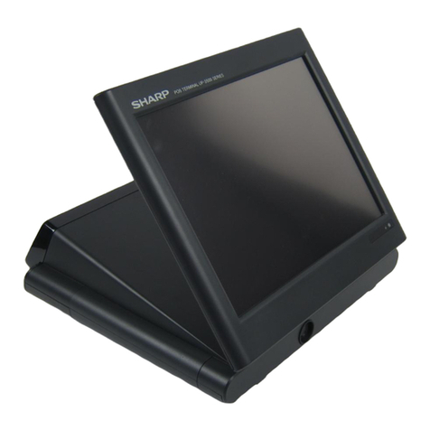
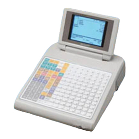
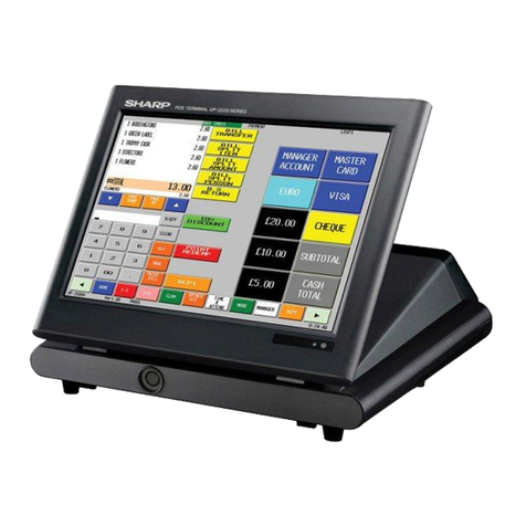
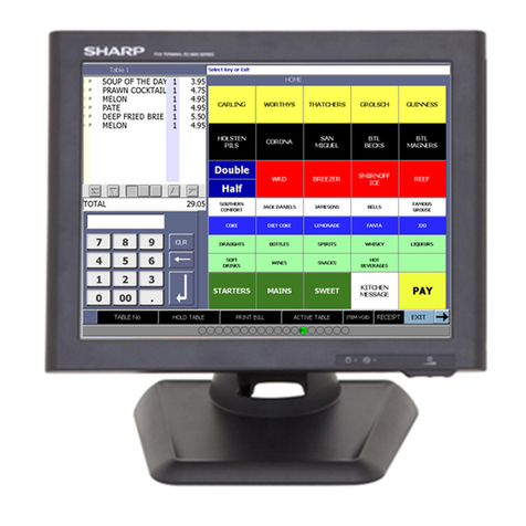
Sharp UP-5900 User manual

CODE : 00Z
qSERVICE MANUAL
CONTENTS
Parts marked with "!" are important for maintaining the safety of the set. Be sure to replace these parts with specified
ones for maintaining the safety and performance of the set.
SHARP CORPORATION This document has been published to be used
for after sales service only.
The contents are subject to change withoutnotice.
UP5900VSME
POS TERMINAL
MODEL UP-5900
CHAPTER 1. SPECIFICATIONS . . . . . . . . . . . . . . . . . . . . . . . . . .1 - 1
CHAPTER 2. OPTIONS . . . . . . . . . . . . . . . . . . . . . . . . . . . . . . . . .2 - 1
CHAPTER 3. SERVICE PRECAUTION . . . . . . . . . . . . . . . . . . . . .3 - 1
CHAPTER 4. DIAGNOSTICS SPECIFICATIONS . . . . . . . . . . . . .4 - 1
CHAPTER 5. CIRCUIT DESCRIPTION . . . . . . . . . . . . . . . . . . . . .5 - 1
CHAPTER 6. BIOS SETUP UTILITY . . . . . . . . . . . . . . . . . . . . . . .6 - 1
CHAPTER 7. HDI RECOVERY PROCEDURES . . . . . . . . . . . . . .7 - 1
CHAPTER 8. ABOUT UTILITY SOFTWARE . . . . . . . . . . . . . . . . .8 - 1
CHAPTER 9. CIRCUIT DIAGRAM . . . . . . . . . . . . . . . . . . . . . . . . .9 - 1
CHAPTER 10.PWB LAYOUT . . . . . . . . . . . . . . . . . . . . . . . . . . . .10 - 1
("V/VK" version)
PARTS GUIDE

UP-5900VS
BATTERY DISPOSAL
Contains Nickel Metal Hydride Battery. Must be Disposed of Properly.
Contact Local Environmental Officials for Disposal Instructions.
CAUTION
RISK OF EXPLOSION IF BATTERY IS REPLACED
BY AN INCORRECT TYPE.
DISPOSE OF USED BATTERIES ACCORDING
TO THE INSTRUCTIONS.
AVOID: SHORT-CIRCUITING THE BATTERY TERMINALS.
KEEP THE BATTERY AWAY FROM FIRE.
*WHEN DISPOSING THE BATTERY, FOLLOW THE LOCAL
RULES AND REGULATIONS.
“BATTERY DISPOSAL”
THIS PRODUCT CONTAINS NICKEL-METAL HYDRIDE BATTERY.
THIS BATTERY MUST BE DISPOSED OF PROPERLY.
REMOVE THE BATTERY FROM THE PRODUCT AND CONTACT FEDERAL OR
STATE ENVIRONMENTAL AGENCIES FOR INFORMATION ON RECYCLING AND
DISPOSAL OPTIONS.
“TRAITEMENT DES ACCUMULATEUR USAGÉS”
CE PRODUIT CONTIENT UN ACCUMULATEUR À NICKEL MÉTAL HYDRIDE.
CET ACCUMULATEUR USAGÉ DOIT ÊTRE TRAITÉ CORRECTEMENT.
ENLEVEZ L’ ACCUMULATEUR DU PRODUIT ET PRENEZ CONTACT AVEC VOTRE
AGENCE ENVIRONNEMENTALE LOCALE POUR DES INFORMATIONS SUR LES
MÉTHODES DE RECYCLAGE ET DE TRAITEMENT.

UP-5900VS SPECIFICATIONS
1 – 1
CHAPTER 1. SPECIFICATIONS
1. APPEARANCE
AC cord
Plug your terminal into a wall outlet that has a dedicated ground before
using.
Power switch
Set the power switch to the ON ( I ) position after the terminal has been
plugged in.
Power indicator
When the power switch is turned on, the power indicator will light up.
The indicator will remain on even while the display’s backlight is off.
■
■■
■ DISPLAY
Display angle
The display may be tilted for the best viewing angle by adjusting the
rear stand.
Be sure to push the release button on the side of the rear stand when
sliding it.
Brightness control
The brightness of the illuminated display can be adjusted using the
brightness control.
Turning the control backwards darkens the display and turning it for-
wards brightens the display.
Caution: The LCD module built in this POS terminal is manufactured
with highly precise technology.
However bright pixels or blank pixels may appear. Also an
irregular color and brightness may occur depending on the
view angle. Please note that this type of phenomena is com-
mon for LCDs and may not be a malfunction.
The backlight in the display is a consumable part.
When the LCD display can no longer be adjusted and becomes darker,
you should replace the LCD module. Consult your authorized SHARP
dealer for further details.
2. RATING
Front view
Operator display
(touch panel)
Money checking
space
Brightness
control
Power indicator
Floppy disk drive
Rear view
Power switch AC cord
Caution: DO NOT insert any device into this
connector unless recommended to do.
Doing so may cause the POS terminal
not to function properly.
DO NOT insert any object into this
switch unless instructed to do.
Doing so may damage or delete the data.
ITEM SPECIFICATIONS
External dimensions 11.8 (W) x 16.3 (D) x 13.5 (H) in. approximately
(298.5 (W) x 415 (D) x 342 (H) mm)
Weight Approximately 15.5lb. (7.0 kg)
Power source 220V~240V AC m10%, 50Hz/60Hz
Power consumption Operating : 92.5W 590mA
Working temperature 32 to 104°F (0 to 40°C)
Button
Brightness control

UP-5900VS SPECIFICATIONS
1 – 2
3. HARDWARE
3-1. DISPLAY
3-2. KEYBOARD
1
11
1TOUCH PANEL
2
22
2POS KEY PAD
VK (U. K.) version : Option (UP-C30PK)
Except VK version : Standard
3-3. PC SYSTEM
3-4. SERIAL PORT
D-SUB 9-pin connector COM1 and COM2 are equipped.
In order to supply +5V power, CI signal and +5V power supply of COM1
and COM2 can be switched.
2 channels of RJ45 Connector COM port are equipped.
COM3 or original I/O address (COM5) can be selected as the 1 chan-
nels of RJ45 COM port.
3-5. EXPANSION SLOT
5V PCI board can built in UP-5900 instead of an ISA PC board.
It has to satisfy with power consumption as follows.
ITEM SPECIFICATION NOTE
Type TFT color LCD with back light High color (16bit)
display
Screen size 12.1" full screen
Dot size 0.0825 x RGB(W) x 0.2825(H) mm
Resolution XGA (1024 x 768 dots)
ITEM SPECIFICATIONS NOTE
Type Touch key (Analog touch panel)
Number of
key positions 4096 (W) x 4096 (H) positions
Control Mouse emulation
ITEM SPECIFICATION NOTE
Type POS rising keyboard
Number of
keys Standard 27 keys
Numeric keys : 11 keys ( 1 to 9,0 and 00)
Capped keys : 16 keys (Key labels are
locally purchased.)
Maximum 30 keys (6x5 matrix)
(Changing key layout by using
ER-11KT7/12KT7/22KT7)
Key layout
ITEM SPECIFICATIONS NOTE
CPU Celeron processor 566MHz
Chip set Intel 440BX + PIIX4e
Graphic controller SMI Lynx3DM4+
Main memory
(for executing MS-DOS,
Application software)
Standard : 128 Mbytes SD RAM
Max. : 256 Mbytes adding DIMM
Video RAM 4 Mbytes Built-in type
BIOS ROM 512 Kbytes Flash ROM
Keyboard controller M38813
Super I/O PC87309
POS system controller PSC2 : LZ9AM22
000
123
456
789
COM1 & COM2: D-sub 9 pin
Pin No. Signal Function I/O
1 CD Data Carrier Detect I
2 RD Receive Data I
3 SD Send Data O
4 ER Data Terminal Ready O
5 SG Signal Ground –
6 DR Data set Ready I
7 RS Request to Send O
8 CS Clear to Send I
9 CI/+5V Ring Indicate / +5V I/
COM3 (or COM5): Modular jack RJ45 8 pin
Pin No. Signal Function I/O
1 RS Request to Send O
2 ER Data terminal Ready I
3 SD Send Data O
4 SG/(+5V) Signal Ground/(+5V) –
5 SG Signal Ground –
6 RD Receive Data I
7 DR Data set Ready I
8 CS Clear to Send I
ITEM SPECIFICATION NOTE
Type PCI bus
Power
consumption +5V max. 0.3A
+12V max. 0.05A
5V PCI board size Short size PC board (Local
procurement item)
Quantity 1 slots

UP-5900VS SPECIFICATIONS
1 – 3
3-6. SHUTDOWN SWITCH
The shutdown switch is used when the OS or application programs are
straying and the system can not return to the normal state.
You must not use this shutdown switch when the UP-5900 is running
normally. Use this switch only when the main power source is not cut off
even if the main unit power switch is set to OFF position. The UP-5900
is turned OFF and the hardware is reset by turning the main power
switch OFF and then pressing the shutdown switch.
[OUT LINE]
The shutdown switch is a single shut type. (Normally OFF position)
[OPERATING METHOD]
The shutdown switch is a push switch. If it is pushed to ON, the UP-
5900 stops supplying the power when the power switch is set into
stand-by mode.
Note: The shutdown operation will be ignored when the power switch is
set to power-on position.
3-7. SYSTEM SWITCH
The system switches are used to preset various system configurations.
[OUT LINE]
The system switches is short pin.
[JUMPER SWITCH]
3-8. POWER SWITCH
[OUT LINE]
The power switch has the positions ON and OFF (Stand-by)
[OPERATING METHOD]
The power switch is a see-saw switch, and it can be tipped toward the
ON or OFF.
4. SOFTWARE
Push ON: This position is used to reset the stand-by mode for
power supply unit during software hang ups.
Release OFF: Usually the shutdown switch needs to be set to this
position when the UP-5900 is operating.
Shut down switch
JP1: Setting of IRQ allocated to COM3.
Position 1-2: COM3 = IRQ4
2-3: COM3 = IRQ11
JP2: Initialization of COMS.
Position 1-2: Initiallize
2-3: Not initiallize
ON position: Usually the power switch needs to be set to this posi-
tion when the POS-terminal is operated.
OFF position: This position can be used to turn the stand-by mode.
When the power switch is set to this position, the power
supply stops automatically. But if the software program
controls the power supply to hold, even if the power
switch is set into this position, power supplying will be
kept until a software program allows power supply to
turn OFF.
Power switch :
ITEM SPECIFICATION NOTE
OS provision Windows 98 Second Edition Local purchased (For V version)
Provided from SHARP (For VK version)
Available OS Windows 2000 Local purchased
Windows NT Work station 4.0 Local purchased
Device drivers POS drivers POS device driver Provided from SHARP
Touch panel driver
VGA device driver
Additional device driver
BIOS Written to the Flash ROM on the Main PWB.
Utility software Touch panel calibration utility program Provided from SHARP
Double tap setup utility program
POS printer utility program
Application software Local purchased

UP-5900VS OPTIONS
2 – 1
CHAPTER 2. OPTIONS
1. SYSTEM CONFIGURATION
2. OPTIONS
No. NAME MODEL NAME DESCRRIPTION
1 Customer display UP-I20DP 2 line 20 digits dot display
2 Customer pole display UP-P20DP 2 line 20 digits dot display
3 MCR (Magnetic Card Reader) UP-E12MR2 for ISO 1 & 2 stripe card
4 Remote drawer ER-03DW 4B/8C
ER-04DW 4B/8C
ER-05DW 5B/8C
5 Receipt/Journal printer ER-01PU 2 station (R/J) thermal printer 45mm width
6 Built-in printer UP-T80BP 1 station thermal printer 80mm width
7 Hand scanner ER-A6HS1 for reading bar code
8 Key pad (Option for VK version) UP-C30PK Std. 27 keys, Max. 30 keys
9 Key kit (Used for key pad : UP-C30PK) ER-11KT7 1 x 1 key top kit
ER-12KT7 1 x 2 key top kit
ER-22KT7 2 x 2 key top kit
Incorporated in Main Unit
RS-232 Communication Connection
max.2
(RS-232)
(Ethernet)
PC Keyboard
<Local item>
Drawer
<Option>
ER-03DW/04DW/05DW
Customer
Poll Displa
<Option>
UP-P20DP
Magnetic
Card Reader
<Option>
UP-E12MR2
Additional DRAM
Memory
<Local item>
Built-in printer
<Option>
UP-T80BP
PC server
<Local item>
Scale
<Local item>
Hand Scanner
<Option>
ER-A6HS1
CAT/EFT
<Local item>
Kitchen video monito
<supplied on site>
Local Printe
<Option> ER-01P
<Local item>
Customer Display
<Option>
UP-I20DP
max.3
Host
UP-5900 Sub
POS terminal
In-line Communication Connection
Remote Printer
<Local item>

UP-5900VS OPTIONS
2 – 2
3. LOCALLY SUPPLIED OPTIONS
*1 Extension RAM module
*2 Hard disk drive
4. SERVICE OPTIONS
No. NAME DESCRIPTION NOTE
1 DIMM 168pin SD-RAM Max. 256Mbytes *1
2 Hard disk drive 2.5 inch type *2
3 PC keyboard PS/2 type PC keyboard
4 Application software
5 Additional device drivers
[Device] 168pin DIMM
[Outline] UP-5900 has a socket as DIMM.
The following DIMM memory specification must be adhered
to.
[Specification] 168pin.DIMM
Type SD-RAM type
Access time PC100 (more than)
Power 3.3V
Refresh cycle 4096/64 msec.
Refresh type AUTO
Power consumption 1400 mA (less than)
[Device] 2.5 inch type Hard disk drive
[Outline] It is necessary to satisfy with 2.5 inch Hard disk drive speci-
fication as follows.
[Specification]
2.5 inch Hard disk drive
Maker Fujitsu
Model MHN2150AT
Capacity 15 Gbytes
Interface ATA-4
No NAME PARTS CODE
PRICE DESCRIPTION
1
Connector cable
for Dongle
(LPT-1)
QCNW-7858BHZZ BL
Relay line from
Terminal to Dongle
2 1 hole clerk key
Thekey No.1to
No.12 are sup-
plied together
with UP-5900.
LKGIM1004BH13 BH Key No.13
LKGIM1004BH14 BH Key No.14
LKGIM1004BH15 BH Key No.15
LKGIM1004BH16 BH Key No.16
LKGIM1004BH17 BH Key No.17
LKGIM1004BH18 BH Key No.18
LKGIM1004BH19 BH Key No.19
LKGIM1004BH20 BH Key No.20
LKGIM1004BH21 BH Key No.21
LKGIM1004BH22 BH Key No.22
LKGIM1004BH23 BH Key No.23
LKGIM1004BH24 BH Key No.24
LKGIM1004BH25 BH Key No.25
LKGIM1004BH26 BH Key No.26
LKGIM1004BH27 BH Key No.27
LKGIM1004BH28 BH Key No.28
LKGIM1004BH29 BH Key No.29
LKGIM1004BH30 BH Key No.30
LKGIM1004BH31 BH Key No.31
LKGIM1004BH32 BH Key No.32
LKGIM1004BH33 BH Key No.33
LKGIM1004BH34 BH Key No.34
LKGIM1004BH35 BH Key No.35
LKGIM1004BH36 BH Key No.36
LKGIM1004BH37 BH Key No.37
LKGIM1004BH38 BH Key No.38
LKGIM1004BH39 BH Key No.39
LKGIM1004BH40 BH Key No.40
LKGIM1004BH41 BH Key No.41
LKGIM1004BH42 BH Key No.42
LKGIM1004BH43 BH Key No.43
LKGIM1004BH44 BH Key No.44
LKGIM1004BH45 BH Key No.45
LKGIM1004BH46 BH Key No.46
LKGIM1004BH47 BH Key No.47
LKGIM1004BH48 BH Key No.48
LKGIM1004BH49 BH Key No.49

UP-5900VS OPTIONS
2 – 3
LKGIM1004BH50 BH Key No.50
LKGIM1004BH51 BH Key No.51
LKGIM1004BH52 BH Key No.52
LKGIM1004BH53 BH Key No.53
LKGIM1004BH54 BH Key No.54
LKGIM1004BH55 BH Key No.55
LKGIM1004BH56 BH Key No.56
LKGIM1004BH57 BH Key No.57
LKGIM1004BH58 BH Key No.58
LKGIM1004BH59 BH Key No.59
LKGIM1004BH60 BH Key No.60
LKGIM1004BH61 BH Key No.61
LKGIM1004BH62 BH Key No.62
LKGIM1004BH63 BH Key No.63
LKGIM1004BH64 BH Key No.64
LKGIM1004BH65 BH Key No.65
LKGIM1004BH66 BH Key No.66
LKGIM1004BH67 BH Key No.67
LKGIM1004BH68 BH Key No.68
LKGIM1004BH69 BH Key No.69
LKGIM1004BH70 BH Key No.70
LKGIM1004BH71 BH Key No.71
LKGIM1004BH72 BH Key No.72
LKGIM1004BH73 BH Key No.73
LKGIM1004BH74 BH Key No.74
LKGIM1004BH75 BH Key No.75
LKGIM1004BH76 BH Key No.76
LKGIM1004BH77 BH Key No.77
LKGIM1004BH78 BH Key No.78
LKGIM1004BH79 BH Key No.79
LKGIM1004BH80 BH Key No.80
LKGIM1004BH81 BH Key No.81
LKGIM1004BH82 BH Key No.82
LKGIM1004BH83 BH Key No.83
LKGIM1004BH84 BH Key No.84
LKGIM1004BH85 BH Key No.85
LKGIM1004BH86 BH Key No.86
LKGIM1004BH87 BH Key No.87
LKGIM1004BH88 BH Key No.88
LKGIM1004BH89 BH Key No.89
LKGIM1004BH90 BH Key No.90
LKGIM1004BH91 BH Key No.91
LKGIM1004BH92 BH Key No.92
LKGIM1004BH93 BH Key No.93
LKGIM1004BH94 BH Key No.94
LKGIM1004BH95 BH Key No.95
LKGIM1004BH96 BH Key No.96
LKGIM1004BH97 BH Key No.97
LKGIM1004BH98 BH Key No.98
LKGIM1004BH99 BH Key No.99
No NAME PARTS CODE
PRICE DESCRIPTION
LKGIM1004BH00 BH Key No.100
LKGIM1004BHA1 BH Key No.101
LKGIM1004BHA2 BH Key No.102
LKGIM1004BHA3 BH Key No.103
LKGIM1004BHA4 BH Key No.104
LKGIM1004BHA5 BH Key No.105
LKGIM1004BHA6 BH Key No.106
LKGIM1004BHA7 BH Key No.107
LKGIM1004BHA8 BH Key No.108
LKGIM1004BHA9 BH Key No.109
LKGIM1004BHA0 BH Key No.110
LKGIM1004BHB1 BH Key No.111
LKGIM1004BHB2 BH Key No.112
LKGIM1004BHB3 BH Key No.113
LKGIM1004BHB4 BH Key No.114
LKGIM1004BHB5 BH Key No.115
LKGIM1004BHB6 BH Key No.116
LKGIM1004BHB7 BH Key No.117
LKGIM1004BHB8 BH Key No.118
LKGIM1004BHB9 BH Key No.119
LKGIM1004BHB0 BH Key No.120
LKGIM1004BHC1 BH Key No.121
LKGIM1004BHC2 BH Key No.122
LKGIM1004BHC3 BH Key No.123
LKGIM1004BHC4 BH Key No.124
LKGIM1004BHC5 BH Key No.125
LKGIM1004BHC6 BH Key No.126
No NAME PARTS CODE
PRICE DESCRIPTION
UP-5900VS OPTIONS
2 – 4
5. SERVICE TOOLS
5-1. PARALLEL LOOP BACK CONNECTOR:
UKOG-2366BHZZ
This connector is connected between CN10/11 of the main PWB and
the parallel port through the Dongle cable (QCNW-7858BHZZ) for
checking the parallel port during execution of diagnostics.
5-2. MCR TEST CARD: UKOG-6718RCZZ
• Used when executing the diagnostics of the UP-E12MR2.
• External view
5-3. RS232 LOOP BACK CONNECTOR:
UKOG-6705RCZZ
Connected to the RS232 connector (D-SUB 9 pin: COM1, COM2) of the
UP-5900 and ER-A8RS, and used to check loop signals when execut-
ing diagnostics.
• Connection diagram
5-4. RS232 MODULAR JACK LOOP BACK
CONNECTOR: UKOG-6729BHZZ
Connected to the RS232 connector (RJ45: COM3) of the UP-5900, and
used to check loop signals when executing diagnostics.
• Connection diagram
No. NAME PARTS CODE PRICE DESCRIPTION
1 Parallel loop back connector UKOG-2366BHZZ BM
2 MCR test card UKOG-6718RCZZ BE for UP-E12MR2
3 RS232 loop back connector UKOG-6705RCZZ BC for RS232 connector
4 RS232 modular jack loop back connector UKOG-6729BHZZ AZ for RJ45 connector
5 TOUCH PEN CPENP1004PCN5 AG
STROBE#
1. D0
2. D1
3. D2
4. D3
5. D4
6. D5
7. D6
8. D7
9. ACK#
10. BUSY
11. PE
12. SLCT
13. AF#
14. ERROR#
15. INIT#
16. SLCTIN#
17. PE
25. PE
CD 1pin
RD 2pin
TD 3pin
DTR 4pin
GND 5pin
DSR 6pin
RTS 7pin
CTS 8pin
RI 9pin
RTS
DTR
TD
GND
GND
RD
DSR
CTS
1pin
2pin
3pin
4pin
5pin
6pin
7pin
8pin

UP-5900VS SERVICE PRECAUTION
3 – 1
CHAPTER 3. SERVICE PRECAUTION
1. CONDITIONS FOR SOLDERING CIRCUIT PARTS
To solder the following parts manually, follow the conditions described below.
Thermal fuse installation fig
2. CAUTIONS ON HANDLING CPU AND
POWER FAN
• When removing or performing maintenance activities on the CPU and
POWER FAN, be sure to handle them with care, because it may
cause abnormal sounds or deteriorate their performance if they are
dropped or exposed to a heavy impact.
3. NOTE FOR HANDLING OF TOUCH
PANEL
• The transparency of the touch panel should be vitally important.
Use clean gloves and masks.
• For handling, do not hold the transparent area, and do not hold the
heat seal connector section to assure reliability.
• Do not overlay touch panels. The edge may damage the surface.
• Do not place heavy things on the touch panel.
• Do not apply a strong shock, and do not drop it.
• When attaching the protection film again, carefully check for dirt. If
there is any dirt, it is transferred.
• To clean dirt on the surface, use a dry, soft cloth or a cloth immersed
in ethyl alcohol.
• Check that the housing does not give stress to the touch panel.
• Be careful not to touch the touch panel with tools.
• The heat seal section is easily disconnected. Be careful not to place
stress to the heat seal section when installing.
• The touch panel is provided with an air groove to make the external
and the internal air pressure equal to each other. If water or oil is put
around the air groove, it may penetrate inside. Be careful to keep the
air groove away from water and oil.
• Do not use sharp objects when making input entrees.
4. NOTE FOR HANDLING OF LCD
• The LCD elements are made of glass. BE careful not to expose them
to strong mechanical shock, or they may be broken. Use extreme
care not to break them.
• If the LCD element is broken and the liquid leaks, avoid contact with
your mouth or eyes. If the liquid comes in contact with your skin or
clothes, immediately clean with soap.
• Use the unit under the rated conditions to prevent against damage.
• Be careful not to place water or other liquids on the display surface.
• The reflection plate and the polarizing plate are easily scratched. BE
careful not to touch them with a hard object such as glass, tweezers
etc. Never hit, push, or rub the surface with hard objects.
• When installing the unit, be careful not to apply stress to the LCD
module. If excessive stress is applied, abnormal display or uneven
color may result.
5. CAUTIONS ON HANDLING FFC
When connecting or disconnecting the ffc, follow the procedures below.
*
**
*How to insert FFC
(1) Pull the slider to the unlock position.
(2) Inserting the FFC
Insert the FFC firmly until the FFC hits the bottom of the connector’s
insulator.
(3) Close the slider to the lock position
PARTS NAME PARTS CODE LOCATION CONDITIONS FOR SOLDERING
Ceramic oscillator RCRMZ7002RCZZ TOUCH PANEL CONTROL PWB: X1 (8M) 270°C/3sec.
RCRMZ7004RCZZ MAIN PWB: X4 (8M)
RCRMZ7004RCZZ MAIN PWB: X3 (7.37M)
Thermal fuse QFS-T0096FCZZ MAIN PWB: F1 300°C/3sec (Length of lead: 15mm or more)
F1
SILICON BOND
Q5
Solder
15mm or more
FFC FFC FFC
CONNECTOR CONNECTOR CONNECTOR
FFC

UP-5900VS SERVICE PRECAUTION
3 – 2
6. PS2 KEYBOARD USABLE FOR UP-5900
The UP-5900 can be externally connected to a keyboard.
The UP-5900’s key BIOS conforms to the PC standard, but this BIOS’s
operation is not compatible for some keyboards.
Some keyboards may cause operation errors due to delicate timing and
conflicts.
It is currently found that the following models of keyboards may mal-
function.
When selecting a keyboard to be connected, test the keyboard in
advance to check that it correctly works.
• Japanese keyboard (106 keys)
Manufactured by IBM: TYPE/MODEL5576-B01 FRUPN66G0507
• English keyboard (101 keys)
Manufactured by NMB Technologies Inc.: Model: RT6651T+
7. PRECAUTION FOR ATTACHING THE
COVER TO THE POWER UNIT
When attaching the cover to the power unit, two lead wires (white x 1,
black x 1) of T1A (transformer) in the power unit may be pinched by the
cover, causing a damage to the wiring. (1)
To avoid this, push two lead wires of T1A between the radiator fin and
T1A before attaching the cover. (2)
8. AC CORD GND WIRE CORE ADDITION
■
■■
■Fixing the core
Procedure 1
Procedure 2
T1A
6)
T1A
1
2
Radiator fin
Radiator fin Radiator fin
Cover
Add the core to the AC cord GND
wire for increasing the EMI margin.
Core added: SC18B (RCORF6698BHZZ)
Wind the AC GND wire around
the core 3 turns (2 windings).
Binding band
Binding position of the
binding band
Pulling direction of
the binding band

UP-5900VS SERVICE PRECAUTION
3 – 3
Procedure 3
■
■■
■
Power unit - Main PWB unit connection cable core change
1. Content of change
The core of the cable connecting the power unit and the main PWB
unit is changed.
■
■■
■LCD cable treatment
Fig.1 LCD cable treatment and core addition
Fig.2 LCD cable treatment (Cable and riser fixing)
Fig.4 Earth Spring 1 (30PK)
l
Fig.5 Earth Spring 2
*Earth Spring 1 and 2 are the same one.
*Earth Spring 1 in Fig.4 is packed together with 30PK.
Procedure 1Pass the binding band through the core as shown in
the photo.
Procedure 2Bind the core as shown in the photo and pull the
band to fix.
Procedure 3Fix so that the binding position of the band does not
extend out of the plate.
Binding position of the
binding band
Inside
The binding position of the band
must be inside of this position.
Core: RCORF2356BHZZ(SC18E)
Pass all the cables (1pin - 15pin)
through the core (SC18E) except for
the power cable. At that time, be
careful not to apply an external force
to the power unit capacitor.
This cable is passed under the
PS unit - Main PWB cable.
Binding band
Binding band
BNF18
Use the binding band for
wiring as shown in the
figure.
30PK standard destination model

UP-5900VS DIAGNOSTICS SPECIFICATIONS
4 – 1
CHAPTER 4. DIAGNOSTICS SPECIFICATIONS
CONTENT
1. General.......................................................................................4-1
2. System configuration..................................................................4-1
3. Service diagnostics ....................................................................4-2
3-1. Service diagnostics getting started...................................4-2
3-2. Selection menu.................................................................4-2
3-3. RAM Diagnostics..............................................................4-2
1) D-RAM Check ............................................................4-2
3-4. ROM Diagnostics..............................................................4-3
1) BIOS ROM Check......................................................4-3
3-5. Real time clock & CMOS RAM Diagnostics.....................4-3
1) Real time clock Check................................................4-3
2) CMOS RAM Check ....................................................4-3
3-6. Key Pad Diagnostics ........................................................4-3
1) Key Pad Check ..........................................................4-3
3-7. Touch Panel Diagnostics..................................................4-4
1) Controller Diagnostics Test........................................4-4
2) Touch Key Pad Test...................................................4-4
3) Linearity Test..............................................................4-4
3-8. Clerk Key Diagnostics ......................................................4-5
1) Clerk Key Check ........................................................4-5
3-9. Printer Diagnostics ...........................................................4-5
1) PARALLEL Loop Back Check....................................4-5
2) PARALLEL Print Check .............................................4-5
3) UP-T180BP Test........................................................4-6
3-10. Serial I/O Diagnostics.......................................................4-6
1) COM1 Check..............................................................4-7
2) COM2 Check..............................................................4-7
3) COM3 Check..............................................................4-7
3-11. Liquid Crystal Display Diagnostics ...................................4-7
1) Liquid Crystal Display Check .....................................4-7
3-12. Magnetic Card Reader Diagnostics..................................4-9
1) Magnetic Card Reader Check....................................4-9
3-13. System Switch Diagnostics ..............................................4-9
1) System Switch............................................................4-9
3-14. Drawer Diagnostics ..........................................................4-9
1) Drawer 1 Check .......................................................4-10
2) Drawer 2 Check .......................................................4-10
3-15. Option Display Diagnostics.............................................4-10
3-16. IDE I/F & HARD DISK Diagnostics.................................4-10
[READ MODE TEST]......................................................4-11
1) Drive Status display .................................................4-11
2) Sequential Seek Test...............................................4-11
3) Random Seek Test ..................................................4-11
4) Seek & Read Test....................................................4-12
5) Target Sector Read Test..........................................4-12
6) HD Dump Test......................................................... 4-13
7) Error lnformation Display ......................................... 4-13
8) Controller check Test............................................... 4-14
[WRITE MODE TEST] ................................................... 4-14
9) Seek&Write/Read-Verify Test.................................. 4-14
10) Target Sector Write/Read-Verify Test...................... 4-15
11) HD Patch Test (Utility) ............................................. 4-15
12) Error Logging Area Clear......................................... 4-15
13) Error table display.................................................... 4-15
14) Other Supplemental Items....................................... 4-15
15) Error Content........................................................... 4-15
16) Error Information Storing Area Description.............. 4-16
3-17. FDD Diagnostics............................................................ 4-16
3-18. FAN & LCD ON/OFF Diagnostics.................................. 4-16
1) FAN & LCD ON/OFF Check.................................... 4-16
3-19. Power Hold Diagnostics................................................. 4-16
1) Power Hold Check................................................... 4-16
3-20. Operating procedure of LAN Interface Diagnostics........ 4-17
■
■■
■DIAGNOSTICS PROGRAM: CREATING AN MS-DOS
STARTING MEDIA (FD)
Before executing the Diagnostic program, you must create the MS-DOS
starting media and copy the Diagnostics program onto it.
HOW TO CREATE AN MS-DOS STARTING MEDIA
1) Execute the command given below on the PC where the MS-
DOS Ver. 6.22 is running and create an MS-DOS starting
media (FD).
MS-DOS (Command) format a: /s
2) Copy the Diagnostics program onto the MS-DOS starting media
(FD).
1. GENERAL
This diagnostic program is used to check the PWB’s, the process, and
the machine of the UP-5900 series in a simplified manner.
This test program is supplied with floppy disks.
2. SYSTEM CONFIGURATION
The system requires the POS terminal, and a PS2 keyboard for diag-
nostic operations.

UP-5900VS DIAGNOSTICS SPECIFICATIONS
4 – 2
3. SERVICE DIAGNOSTICS
3-1. SERVICE DIAGNOSTICS GETTING STARTED
GETTING STARTED:
Execute “SRV.BAT” by entering the command with the PS2 keyboard
as follows:
A:\> SRV b
“A:\>” is the DOS prompt. (Used by the FD)
*Do not load any device drivers when using this program.
*To operate other applications after performing this program, it is rec-
ommended to re-boot the machine.
3-2. SELECTION MENU
The diagnostics menu is started and the following menu is displayed.
The highlighted cursor is moved by the cursor keys (UP 2and
DOWN 4) of the PS2 keyboard. Move the cursor to the desired item,
and press the Enter key to execute the selected diagnostics program.
When the selected diagnostics program is completed, the display
returns to the menu screen by pressing the ESC key. Select “Diagnos-
tics End” and press the Enter key to terminate the diagnostics.
3-3. RAM DIAGNOSTICS
This program is used to test the standard memory and the extension
memory.
1) D-RAM CHECK
1Checking content
All memory areas are checked in blocks of 512KB. The checking
procedures are as follows:
i. Test data 5555H is written to all the test areas.
ii. Test data and read data are compared by each word, If it is
O.K., test data AAAAH is written to the test area.
iii. Test data and read data are compared by each word, If it is
O.K., test data 5555H is written to the test area.
iv. Test data 0000H is written to all the test areas.
v. Test data and read data are compared by each word, If it is
O.K., test data FFFFH is written to the test area.
vi. Test data and read data are compared by each word, If it is
O.K., test data 0000H is written to the test area.
When an error occurs during the test, the error address and data are
displayed and the test is stopped.
For the extended memory test, the value is set in the setup of the
read test and is made to the area in increments of 512KB.
2Display
The error address and the error data are displayed only when an
error occurs. (When no errors occur, they are not displayed.)
3Terminating method
After completion of the test, press the Esc key to terminate and
return to the service diagnostics menu.
RAM Diagnostics
Diagnostics for Service
SHARP PC-POS System Diagnostic Series
ROM Diagnostics
Real time clock & CMOS RAM Diagnostics
Touch Panel Diagnostics
Key Pad Diagnostics
Version 1.00A
Clerk Key Diagnostics
Serial I/O Diagnostics
Printer Diagnostics
LCD (Liquid Crystal Display) Diagnostics
MCR (Magnetic Card Reader) Diagnostics
System Switch Diagnostics
Drawer Diagnostics
Diagnostics End
IDE I/F & Controller Diagnostics
Option Display Diagnostics
FAN&LCD ON/OFF Diagnostics
FDD Diagnostics
Power Hold Diagnostics
IV
D-RAM Check
Memory size :xxxxKB PASS !!(or ERROR !!)
Error Address xxxxxxH Write Data xxxxH Read Data xxxxH

UP-5900VS DIAGNOSTICS SPECIFICATIONS
4 – 3
3-4. ROM DIAGNOSTICS
The BIOS ROM, is tested.
1) BIOS ROM CHECK
1Checking content
The BIOS ROM version is displayed.
2Display
3Terminating method
After the test result is displayed, press Esc key to terminate and
return to the service diagnostics menu.
3-5. REAL TIME CLOCK & CMOS RAM DIAGNOSTICS
RTC and CMOS RAM check is performed.
The following menu is displayed. The highlighted cursor is moved by
the cursor keys (UP 2and DOWN 4) of the PS2 keyboard. Move the
cursor to the desired item, and then press the Enter key to execute the
selected diagnostics program. When the selected diagnostics program
is completed. Pressing the Esc key again returns to the service diag-
nostics menu.
1) REAL TIME CLOCK CHECK
1Checking content
RTC timer function and RTC clock function are tested.
2Display
3Terminating method
After the test result is displayed, press the Esc key to terminate and
return to the RTC and CMOS RAM diagnostics menu.
2) CMOS RAM CHECK
1Checking content
The read/write check is performed for the CMOS-RAM when setting
up. The checking procedure is as follows:
i. Test address data is saved to the main memory.
ii. Test data 55H is written to the test address.
iii. Test data and read data are compared, and test data AAH is
written to the test address.
iv. Test data and read data are compared.
v. The saved test data is written to the test area.
vi. The address is incremented until it becomes 3FH.
If POFF interruption is generated during the test, the test is stopped
and the saved data is written to the test area within 50ms.
2Display
The error address and error bit are displayed only when an error
occurs. (When no error occurs, they are not displayed.)
3Terminating method
After the test result is displayed, press the Esc key to terminate and
return to the RTC and CMOS RAM diagnostics menu.
3-6. KEY PAD DIAGNOSTICS
1) KEY PAD CHECK
The UP-C30PK key test is performed. In the UP-C30PK, keys are
detected by matrix scan of KBC (M38802M270).
1Display
BIOS ROM Check
Version - ROM : SHPUP****
The version is displayed.
Real time clock & CMOS RAM Diagnostics
Real time clock Check
CMOS RAM Check
Real time clock Check
RTC Timer Check : PASS !!(or ERROR !!)
RTC Clock Check : PASS !!(or ERROR !!)
CMOS-RAM Check
RTC RAM Check : PASS !!(or ERROR !!)
Error Address xxxxxH Write Data xxH Read Data xxH
Key Pad Diagnostics
ESC
When this is pressed, the buzzer sounds
and the color changes.
Press ESC key to exit.

UP-5900VS DIAGNOSTICS SPECIFICATIONS
4 – 4
2Content
When a key is pressed, its color changes and the key catch sound is
made.
The keys to be checked and their positions are as shown below.
3End
Press the ESC key to terminate the test.
3-7. TOUCH PANEL DIAGNOSTICS
The touch panel and its controller are checked. Communication with the
controller is performed by the 8250 built in the gate array PSC2.
The controller diag check, the touch keypad test, and the linearity test
are performed.
The initial display is as follows:
1) CONTROLLER DIAGNOSTICS TEST
1Checking content
After initializing the controller, the diagnostic command is executed.
The procedures are as follows:
• One byte of sample data (FFh) is sent and a wait state of 100ms
is made.
• The reset command (80h) is sent and a wait state for the end
code (2 bytes: 90h and 00h) from the controller is made.
• The diagnostic command (2 bytes: 89h, any one-byte data) is
executed, and a wait state for the end code (3 bytes: 90h, return
code, any one-byte data) is made.
• If an error occurs the error display is made with the return code.
*To exit from the controller diagnostic test, press the Esc key dur-
ing the wait state for the end code response.
2Display
3Terminating method
After the test result is displayed, press the Esc key to terminate and
return to the Touch panel diagnostics menu.
2) TOUCH KEY PAD TEST
1Checking content
The driver function call is used. The is displayed at the four
corners of the LCD sequentially.
(In the sequence of upper right, upper left, lower left, lower right.)
When the is touched by the operator, the buzzer sounds and
the screen turns to .
2Display
3Terminating method
Touch all four areas or press the Esc key to terminate and
return to the Touch panel diagnostics menu.
3) LINEARITY TEST
1Checking content
Red lines are displayed at both sides of the blue line at the center.
The operator must touch the blue line without touching the red lines
and drag from top to bottom.
The touched part of the blue line is changed to white.
If the red line is touched, an error message is issued.
2Display
3Terminating method
Press the Esc key to terminate and return to the Touch panel diag-
nostics menu.
Return code Content
0Ah ROM error
0Bh RAM error
0Ch Panel voltage error
0Dh Reserve
0Eh EPROM write error
0Fh EPROM read error
10h EPROM check sum error
Back
Space
L-Shift
L-Alt
L-Ctrl
Tab
F10 Delete
6
3
9
F5
5
2
8
F4
4
0
1
7
ESC
Space
Enter
Touch Panel Diagnostics
Touch Key Pad Test
Linearity
Controller DiagTest
EPROM
Controller Diag Test
ROM Error!!
RAM Error!!
PANEL Voltage Error!!
Error!!
EPROM Write Error!!
EPROM SUM Error!!
Error!!
Pass!!
or
Read Error!!
Touch Key Pad Test
Touch Cursor !!
Test
Complete!
(Error!!)
About 2cm
About 1cm
Displayed after termination.
Red line
Blue line
Red line
Linearity

UP-5900VS DIAGNOSTICS SPECIFICATIONS
4 – 5
3-8. CLERK KEY DIAGNOSTICS
(European model only)
The clerk key input test is performed.
Pressing the Esc key returns to the serviceman diagnostics menu.
1) CLERK KEY CHECK
1Checking content
Key code inserted to the clerk key switch which is then displayed in
a decimal value.
2Display
The clerk code is displayed at XX.
3Terminating method.
Press the Esc key to terminate and return to the service diagnostics
menu.
3-9. PRINTER DIAGNOSTICS
The parallel interface (standard) is tested.
The following menu is displayed.
The highlighted cursor is moved by the cursor keys (UP 2and DOWN 4)
on the PS2 keyboard. Move the cursor to the desired item and press the
Enter key to execute the selected diagnostics program.
When the selected diagnostics program is completed, the display
returns to the menu screen. Pressing the Esc key returns to the service
diagnostics menu.
1) PARALLEL LOOP BACK CHECK
1Checking content
To check the parallel port DSub 25 pin, use the connector (UKOG-
2366BHZZ) for Parallel Loop Back Test.
Wiring is as shown below:
Perform the loop back check with the following combination of paral-
lel ports (standard provision).
2Display
3Terminating method.
Press the Esc key to terminate and return to the Printer diagnostics
menu.
2) PARALLEL Print Check
1Checking content
The print check is performed for the standard port PARALLEL at I/O
address 378H ~ 37FH. In the print check mode the D-Sub 25 pin
connector is connected with a printer to allow a print pattern test.
The test procedures are as follows:
i. Data of 55H is written to I/O address 378H, and the same
address is read. If the read data is not 55H, “PARALLEL Chan-
nel Disabled” is displayed and the following check is not per-
formed.
ii. Characters of 20H ~ 7FH (ASCII code) are printed and the line
is changed.
This procedure is repeated for 5 times.
2Display
“PARALLEL Channel Disabled” is displayed only when no access to
PARALLEL is allowed.
3Terminating method.
Press the Esc key to terminate and return to the Printer diagnostics
menu.
Clerk Key Check
Clerk Key Code : xx
Printer Diagnostics
PARALLEL Loop Back Check
PARALLEL Print Check
Option(UP-T80BP)
Print Check
Standard
(D0) – (STROBE#)
(D1) – (AF#)
(D2) – (INIT#)
(D3) – (SLCTIN#)
(D4) – (ERROR#) – (SLCT)
(D5) – (PE)
(D6) – (ACK#)
(D7) – (BUSY)
Printer Diagnostics
PARALLEL Loop Back
D0-STROB : OK! (or ERROR!)
D1-AF : OK! (or ERROR!)
D2-INT : OK! (or ERROR!)
D3-SLCTN : OK! (or ERROR!)
D4-ERROR & SLCT : OK! (or ERROR!)
D5-PE : OK! (or ERROR!)
D6-ACK : OK! (or ERROR!)
D7-BUSY : OK! (or ERROR!)
PARALLEL Print Check
PARALLEL Channel Disabled

UP-5900VS DIAGNOSTICS SPECIFICATIONS
4 – 6
3) UP-T80BP TEST
1Display
On the above screen the setting appears in the box.
The Count can be set from “01” up to “99”. If “00” is set, printing
does not stop until the ESC key is pressed.
2Testing
The following patterns are printed and the paper cut command is
sent by the specified number of times to the Serial output of I/O
address 980H to 987H.
3Error message
The following error message appears if a communication error
occurs with the UP-T80BP.
4End of testing
The testing is finished after printing is made by the specified number
of times or by pressing the ESC key.
3-10. SERIAL I/O DIAGNOSTICS
The serial interface of UP-5900 is performed. To test the 9pin D-Sub
port, connect the D-Sub loop back connector (UKOG-6705RCZZ).
To test the RJ45 port, connect the loop back connector (UKOG-
6729BHZZ).
Loop back connector (UKOG-6705RCZZ) wiring diagram
Loop back connector (UKOG-6729BHZZ) wiring diagram
The UP-5900’s 9-pin D-sub ports are used as COM1 and 2. The UP-
5900 also provides a RJ45 port is used as COM3.
The following menu is displayed.
The highlighted cursor is moved by the cursor keys (UP
2
and DOWN
4
)
of the PS2 keyboard. Move the cursor to the desired item, and press the
Enter key to execute the selected diagnostics program.
When the selected diagnostics program is completed, the display
returns to the menu screen. Pressing the Esc key returns to the service
diagnostics menu.
Count ? = 01 (00-99)
Pass Count = XX
Hit ESC Key to Stop
Print Check
YOUR RECEIPT
THANK YOU
********************
UP-T80BP I/F ERROR
Hit ESC Key to Stop
Print Check
CD 1pin
RD 2pin
TD 3pin
DTR 4pin
GND 5pin
DSR 6pin
RTS 7pin
CTS 8pin
RI 9pin
RTS
DTR
TD
GND
GND
RD
DSR
CTS
1pin
2pin
3pin
4pin
5pin
6pin
7pin
8pin
Serial I/O Diagnostics
COM1 Check
COM2 Check
COM3 Check

UP-5900VS DIAGNOSTICS SPECIFICATIONS
4 – 7
1) COM1 CHECK
1Content
The loop back check is performed for the UART at I/O address
3F8H ~ 3FFH. The test procedures are as follows:
i. UART setting is made. If access is denied to UART at that time,
“COM1 Disabled” is displayed and the following check is not
performed.
ii. RTS signal is turned on/off to check that CD, CTS signal is nor-
mally operating. In case of any abnormality, ERROR is dis-
played.
iii. DTR signal is turned on/off to check that DSR, RI signal is nor-
mally operating. In case of any error, ERROR is displayed.
When an error occurs in procedure i or ii, the following test is
not performed.
iv. Set the baud rate to 19200bps asynchronous. 256 byte data of
00H ~ FFH is transmitted from SD signal. Data received at RD
signal is compared to check that the both are the same. If the
output data is not returned for 5 sec or more, an ERROR is dis-
played and the test is terminated.
v. An interruption signal is issued from UART and the number of
generated interruption request signal is displayed.
2Display
The number of the interruption request signal is displayed at XX.
If no access is allowed to COM1 UART, the following display is
made.
3Terminating method.
Press the Esc key to terminate and return to the Serial I/O diagnos-
tics menu.
2) COM2 CHECK
1Checking content
The loop back check is performed for the UART at I/O address
2F8H ~ 2FFH. The check procedure, the display, and the terminat-
ing method are the same as COM1 Check.
3) COM3 CHECK
1Checking content
The loop back check is performed for the UART at I/O address
3E8H.
When the RJ-45 port of the UP-5900 main unit is assigned to
COM3, the following points are different from COM1 Check :
1Content
• RTS-CTS is not checked.
• DTR-RI is not checked.
2Display
• RTS-CTS is not displayed.
• DTR-RI is not displayed.
COM3 is checked as well as COM1 except at the above 2 points.
3-11. LIQUID CRYSTAL DISPLAY DIAGNOSTICS
LCD test is performed.
The following patterns are displayed in sequence. Pressing the space
bar proceeds to the next display. Pressing the space bar at the final pat-
tern or pressing the Esc key during the test, will return the display to the
service diagnostics menu.
1) LIQUID CRYSTAL DISPLAY CHECK
1Checking content
The test patterns are displayed in the following test procedures.
Pressing the space bar moves to the next pattern.
i. Black-and-white pattern in 1 dot interval
ii. Reversed pattern of pattern i.
iii. Vertical stripe pattern in 1 dot interval
Serial I/O COM1 Check
RTS - CD : PASS !!(or ERROR !!)
DTR - DSR : PASS !!(or ERROR !!)
TD - RD : PASS !!(or ERROR !!)
INTERRUPT : IRQ XX
RTS - CTS : PASS !!(or ERROR !!)
DTR - RI : PASS !!(or ERROR !!)
Serial I/O COM1 Check
COM1 Channel Disabled

UP-5900VS DIAGNOSTICS SPECIFICATIONS
4 – 8
iv. Reversed pattern of pattern iii.
v. Horizontal stripe pattern in 1 dot interval
vi. Reversed pattern of pattern v.
vii. “H” pattern (80 digits x 35 lines) In the 35th line, only 78 digits of
“H” are displayed.
(The actual display range is 25 lines. Scroll for 10 lines to
check.)
viii. Gradation pattern from black to white in 16 gradations
ix. All white pattern
x. Color bar (16 colors)
Color bars of 16 colors are displayed.
xi. Color pattern (256 colors)
Color pattern of 256 colors is displayed. The displayed colors
are the default pallet.
Arrange RAMDAC register No. 0 ~ 255 from the upper left.
xii. Backlight OFF
The backlight is turned off without turning off the display.
xiii. Backlight ON
2Terminating method
Press the space bar or Esc key to terminate and return to the ser-
vice diagnostics menu.
HHHHHHHHHHHHHHHHHHHHHHHHHHHHHHHHHHHHHHHHHHHHHHHHHHHHHHHHHHHHHHHHHHHHHHHHHHH
HHHHHHHHHHHHHHHHHHHHHHHHHHHHHHHHHHHHHHHHHHHHHHHHHHHHHHHHHHHHHHHHHHHHHHHHHH
Black
Blue
Green
Cyan
Red
Magenta
Brown
White
Gray
Light blue
Light green
Light cyan
Light red
Light magenta
Light yellow
Light white
Other Sharp Touch Terminal manuals

Sharp
Sharp UP-3301 User manual

Sharp
Sharp ER-A750 User manual

Sharp
Sharp UP-X300CF256 User manual

Sharp
Sharp UP-X500 User manual

Sharp
Sharp ER-A770 User manual

Sharp
Sharp UP-3500 User manual

Sharp
Sharp UP-5700 User manual

Sharp
Sharp UP-3300 Owner's manual

Sharp
Sharp UP-X500 User manual

Sharp
Sharp RZ-E601 User manual