Eton NCS 700 Guide

EINBAU /BEDIENUNG
INSTALLATION / OPERATION
NCS 700
NCS 525
NCS 400
NCS 700
NCS 525
NCS 400
2-WEGE SYSTEM / 2-WAY SYSTEM
GERMAN HIGH TECHNOLOGY

Achtung !
Bitte lesen Sie alle Warnungen in dieser Anleitung. Diese
Informationen sind eingerahmt hervorgehoben und eingefügt, um
Sie über mögliche persönliche Schäden oder Beschädigungen von
Sachwerten zu informieren.
Hörschäden
Anhaltendes, übermäßiges Ausgesetztsein von Lautstärken
über 85 dB kann das Hörvermögen auf Dauer beeinträchtigen. ETON
Lautsprechersysteme sind imstande, auch Lautstärken über 85 dB zu
produzieren.
Lautstärke und Fahrerbewußtsein
Der Gebrauch von Musikanlagen kann das Hören von
wichtigen Verkehrsgeräuschenbehindern und dadurch während der
Fahrt Gefahren auslösen.
ETON übernimmt keine Verantwortung für Gehörschäden,
körperliche Schäden oder Sachschäden, die aus dem Gebrauch oder
Mißbrauch seiner Produkte entstehen.
Attention !
Please read all warnings found in this manual. This
information is highlighted in frames and is included to inform you of
the potential danger of personal injury or damage to property.
Hearing Damage
Continuous, excessive exposure to sound pressure levels in
excess of 85 dB can cause a loss of hearing. ETON components are
capable of producing sound pressure levels greater than 85 dB.
Volume and Driver Awareness
Use of sound components can impair your ability to hear
necessary traffic sounds and may constitute a hazard while driving
your automobile.
ETON accepts no liability for hearing loss, bodily injury or
property damage as a result of use or misuse of this product.

Nehmen Sie Ihr Fahrzeug nicht in Betrieb, bevor alle Komponenten
des Lautsprechersystems fest und sicher eingebaut sind. Lose Teile
können im Falle eines plötzlichen Bremsmanövers oder eines Unfalls
zu gefährlichen, fliegenden Geschossen werden.
Bohren oder schrauben Sie nicht in eine Fahrzeugverkleidung oder
einen teppichbezogenen Boden, bevor Sie sich versichert haben daß
darunter keine wichtigen Teile oder Kabel sind. Achten Sie auf Benzin-
, Brems-, Ölleitungen und elektrische Kabel bei der Planung für die
Montage.
Trennen Sie vor Beginn der Montage den Massepol (-) von der Fahr-
zeugbatterie, um eventuelle Kurzschlüsse zu verhindern.
Vorsicht beim Entfernen von Innenverkleidungen. Die Fahrzeugher-
steller verwenden verschiedenste Befestigungsteile die bei der De-
montage beschädigt werden können.
MONTAGE
Einbauplätze wählen
Für eine einfache Montage benutzen Sie die vorgesehenen Original-Ein-
bauplätze. Diese Wahl bringt erheblich kürzere Montagedauer und beste
optische Integration.
Vermeiden Sie Plätze hinter dicken Stoffen. Dies kann, besonders bei
Hochtönern, den Klang und die Lautstärke beeinträchtigen.
Nur NCS 525 /700
Zu nahe Montage der Hochtöner an reflektierende Flächen kann den
Stereoeffekt beeinträchtigen. Jedes Mittel/Tieftöner und Hochtöner-Paar sollte
nicht weiter als 60 cm auseinander liegen.
Wenn Sie zuerst den Mittel/Tieftöner montieren und die Anschlußkabel ver-
legen, können Sie die optimale Position für die Hochtöner an verschiedenen
Plätzen ausprobieren, bevor Sie diese fest einbauen.
Einbau der Mittel/Tieftöner
Können Sie den Lautsprecher nicht am Original-Einbauplatz montieren, ist der
allgemein meistgenutzte Ort die Türverkleidung.
1. Nach der Wahl des entsprechenden Platzes entfernen Sie vorsichtig
die Verkleidung. Versichern Sie sich, daß genügend Einbautiefe vor-
handen ist und keine beweglichen Teile (Fenster, Fensterkurbel) in
ihrer Funktion behindert werden.

3. Bei der Verwendung von Gittern oder Verkleidungen vor dem Laut-
sprecher versichern Sie sich, daß genügend Raum für den Weg des
Lautsprecher-Konus vorhanden ist. Sollte der Abstand nicht ausrei-
chen, kann der Konus gegen die Verkleidung vibrieren und der
Lautsprecher dadurch beschädigt werden.
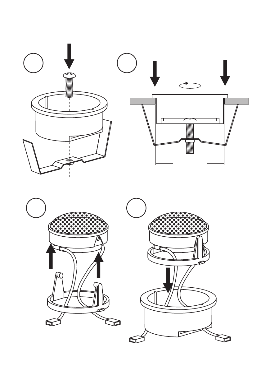
Einbau der Hochtöner (Nur NCS 525/700)
Die Hochtöner können eingebaut oder aufgebaut werden. Bedenken Sie, daß
sich bei Montage in der Türe die Halterungen der Hochtöner durch häufiges
Türenschlagen lösen können.
1. Einbau: Schneiden Sie unter Zuhilfenahme der beiliegenden Bohr-
schablone ein entsprechendes Loch. Verlegen Sie das zu-
führende Anschlußkabel und montieren die Teile wie in
Abbildung 2gezeigt.
Die Besonderheit des ETON Einbaugehäuses ist, daß Sie den Hoch-
tönereinsatz schwenken und drehen können, um die optimale Ab-
strahlrichtung zu Ihrer Sitzposition zu erzielen. Siehe Abbilung 3.
Demontage: Um den Hochtönereinsatz aus dem Einbaugehäuse zu
entfernen, drehen Sie den Einsatz in mittlere Position, nehmen zwei
metallene Rundstäbchen mit ø1,0 mm und stecken diese bis zum
Anschlag in die beiden Öffnungen rechts und links des Einsatzes.
Durch Schwenken des Hochtöners können Sie ihn nun nach oben
entnehmen.
2. Aufbau: Bohren Sie unter Zuhilfenahme des Aufbaugehäuses
zwei Löcher für die Befestigungsschrauben und ein Loch für das zuführ-
ende Anschlußkabel. Beachten Sie dabei die von Ihnen
gewünschte Neigung des Aufbaugehäuses. Montieren Sie die Teile wie
in Abbildung 4gezeigt.
2. Schneiden Sie unter Zuhilfenahme der beiliegenden Bohrschablone
ein entsprechendes Loch in die Verkleidung und eventuell in das da-
hinterliegende Karosserieblech und bohren die Löcher für die Befe-
stigungsschrauben. Montieren Sie die Teile wie in Abbildung 1dar-
gestellt.
Achtung: Sollen zur Montage der Lautsprecher Karosseriebleche
ausgeschnitten oder entfernt werden, nehmen Sie Kontakt mit Ihrer
Fahrzeug-Vertragswerkstatt auf. Bei Beschädigungen tragender Kar-
osserieteile kann die Betriebserlaubnis erlöschen.
Vorsicht beim Entfernen von Innenverkleidungen. Die Fahrzeugher-
steller verwenden verschiedenste Befestigungsteile, die bei der De-
montage beschädigt werden können.

Befestigung der passiven Weiche (Nur NCS 525/700)
1. Bohren Sie unter Zuhilfenahme der Weiche vier Löcher für die Be-
festigungsschrauben.
Schrauben Sie die Weiche fest wie inAbbildung 5 gezeigt.
Achten Sie immer darauf, wenn Sie Kabel durch ein Blech verlegen, daß das
Kabel durch eine Kunststoffdurchführung geschützt ist und nicht von einer
scharfen Blechkante beschädigt werden kann, um Kurzschlüsse und daraus
resultierende Schäden am Verstärker oder der Lautsprecher zu vermeiden.
1. Folgen Sie den Anschlußplänen der Abildungen 6und 7, um das
Lautsprechersystem mit Ihrem Autoradio und eventuell mit einem
Verstärker zu verbinden.
Achten Sie unbedingt auf die Polarität aller Anschlüsse.
(+ auf +, - auf -)
Die Hochtöner dürfen nur über eine Weiche angeschlossen sein.
2. Nun können Sie die Fahrzeug-Batterie wieder anklemmen und das
Lautsprecher-System testen.
Wichtig: Befestigen Sie die Weiche an einem Ort, der leichten Zugang
für den späteren Anschluß und Abgleich ermöglicht.
Bitte verwenden Sie nur die beigefügten Krempkontakte für die An-
schlüsse und löten Sie diese nicht an, um eine Beschädigung der
Komponenten zu vermeiden.
ELEKTRISCHER ANSCHLUSS
Abgleich der passiven Weiche (Nur NCS 525/700)
Abhängig vom Einbauort in Ihrem Fahrzeug lassen sich Lautstärke
und Phasen des Hochtöners an der Frequenzweiche einstellen. (Wird
ein Hochtöner z.B. in Ohrennähe des Fahrers und zu ihm ausge-
richtet eingebaut, sollte der Drehschalter in Stellung -2 bzw. -3 dB
gedreht werden. Soll der Hochtöner jedoch versenkt im Armaturen-
brett plaziert sein, sollte der Drehschalter in Stellung +1 bzw. +3 dB
gebracht werden). Richtig ist die Stellung des Phasenschalters, we nn
der Mitteltonbereich lauter empfunden wird. Die Schalter an bei-d e n
Frequenzweichen (linker und rechter Kanal) müssen gleich ein-
gestellt sein.
Achtung: Schließen Sie die Höchtöner nie ohne Frequenzweiche direkt

Do not use your automobile until all components of the loudspeaker
system have been secured to the interior framework. Failure to do so
may turn a component into a dangerous, flying projectile during a
sudden stop or accident.
Do not drill or drive screws through any vehicle interior or carpeted
floor before inspecting the underside for potential punctures to control
lines or cables. Be sure to avoid all fuel lines, brake lines, electrical
cables or oil lines when planning the installation.
Before beginning installation of the loudspeaker system remove the
minus connector from the automobile battery in order to avoid
possible short circuits.
Caution: Use care when removing interior trim panels. Car manu-
facturers use a variety of fastening devices that can be damaged in the
disassembly process.
MECHANICAL INSTALLATION
Choosing a Location
For ease of installation use original factory speaker locations. Using these
positions will save considerable installation time and provide the best optical
integration. Avoid installing speakers behind thick stock fabric or cloth. This
could - especially in the case of tweeters - restrict output and reduce sound
volume.
Applies only to NCS 525 /700
Installation too close to reflective surfaces can negatively affect stereo imaging.
The distance between each mid/woofer and tweeter pair should not exceed 60
cm. We suggest first mounting the mid/woofer and attaching the cables. Then
you can determine the optimum tweeter location by auditioning the tweeters at
several positions in your automobile before permanent installation.
Installation of Mid/Woofer
If it is not possible to install the loudspeaker in the original factory speaker
location, the most used position is the door panel.
1. After choosing a location, carefully remove the trim panels. Be sure
that sufficient mounting depth is available and that no moveable
mechanical parts (window, window regulator handle) are restricted
in their functionality.

3. If you plan to use grilles or panels in front of the loudspeaker, en- s u r e
that sufficient space is available for the path of the loudspeaker cone.
Should the distance not be sufficient, the cone could vibrate
against the grille or panel thus damaging the loudspeaker.
Installing the Tweeters (only NCS 525/700)
The tweeters can be flush- and surface-mounted. Consider that repeated
opening and closing of the car door can result in loosening of the tweeter
fastening devices, when the loudspeaker is mounted in the door panel.
1. Flush mounting: Use the enclosed drilling template to cut a suit-
able hole. Lay the leading connector cable and mount the parts as
The specialty of the ETON mounting cabinet is that the tweeter ele-
ment can be turned and swiveled to achieve the optimum hearing
path to your sitting position. See figure 3.
Disassambly: To remove the tweeter element from the mounting
cabinet turn the element to its middle position and place two round
metal rods with a diameter of 1,0 mm to the limit in both openings
right and left of the tweeter element. By swiveling of the tweeter you
can now move it upwards and remove it.
2. Surface mounting: Drill two holes for the fastening screws and one
hole for the leading connector cable using the mounting cabinet as
a guide. Consider the preferred incline of the mounting cabinet.
Mount the parts as shown in figure 4.
2. Use the enclosed drilling template to cut a suitable hole in the trim
panel and, if necessary, in the sheet metal behind. Drill holes for the
fastening screws. Mount the parts as shown in figure 1.
Attention: If sheet metal must be cut or removed contact your
authorized car dealer for professional advice. By damage to sup-
porting body structures the safety certificate may be withdrawn.
Caution: Use care when removing interior trim panels. Car manu-
facturers use a variety of fastening devices that can be damaged in the
disassembly process.

Tuning of the Passive Crossover (only NCS 525/700)
Dependant upon the location in your automobile, volume and pha-
ses of the tweeter can be adjusted by the crossover. For example, if a
tweeter is installed close to the listenor’s ears, directed towards him,
the rotary-switch should be turned into position -2 respectively -3 dB.
However, should the tweeter be placed in the dash board, the
switch should be turned into position +1 respectively +3 dB. The
position of the phase switch is correct, when the midrange can be
distinguished as louder. The switches on both crossovers (left and
right channel) must be adjusted identically.
See figure 6.
Whenever you run wires through sheet metal, use tape or grommets to properly
insulate the metal edges from cable jackets. This technique prevents chafing
and possible short circuits that could damage an amplifier or the loudspeakers.
1. Follow the wiring diagrams figures 6and 7 to connect the loud-
speaker system to your automobile radio and possibly to an ampli-
fier. Be very careful of correct polarity of all connections.
(+ to +, - to -)
The tweeters should only be installed through a crossover.
2. Replace the automobile battery connector and test the loudspeaker
system.
Important: Mount the crossover in a location that will provide easy
access for later connection and system tuning.
Please use only the enclosed crimp-type terminals when connecting
and do not solder them to avoid possible damage to the compo- nents.
Caution: Do not connect the tweeters directly with the amplifier / radio
ELECTRICAL INSTALLATION
Fastening of the Passive Crossover (only NCS 525/700)
1. Drill four holes for the fastening screws using the uncovered cross-
over. Secure the crossover with four screws as shown in figure 5.

Einbau Mittel/Tieftöner
Flush mount of Mid/Woofer
NCS 700
Abbildung 1
Figure 1
Blechmutter
Tinnerman Nut
Blechschraube
Self-Threading Screw
Ring und Gitter
(Zubehör - optional)
Ring and grille
(Accessories - optional)
Ring und Gitter
(Zubehör - optional)
Ring and grille
(Accessories - optional)
Abbrechohren-
wenn nur Platz für
2 oder 3 Anschraub-
punkte ist.
Break off Ears-
if there is space for
2 or 3 mounting
holes only.
NCS 400/525
NCS 400
NCS 525
Blechmutter
Tinnerman Nut
Blechschraube
Self-Threading Screw

1
3 4
2
ø 46,0 mm
Einbau Hochtöner
Flush mount of Tweeter
+ red
_black
Cable:
Abbildung 2
Figure 2
Nur NCS 525/700
Only NCS 525/700

12
Demontage:
Disassembly:
Schwenken und Drehen
Swivel and turn
Einbau Hochtöner
Flush mount of Tweeter
Aufbau Hochtöner
Surface mount of Tweeter
Nur NCS 525/700
Only NCS 525/700
Nur NCS 525/700
Only NCS 525/700
Lautsprecher in mittlerer Position !
Speaker in middle position !
ø 1,0 mm
Abbildung 3
Figure 3
Abbildung 4
Figure 4
+ red
_black
Cable:

Vom
Verstärker
From
Amplifier
Hoch-
töner
To
Tweeter
Mittel-
Tieftöner
To Mid/
Woofer
Montage der Weiche
Installing the crossover
Anschlußplan für Weiche
Wiring diagram crossover
Abstimmung der Weiche
Tuning of the crossover
Abbildung 5
Figure 5
Abbildung 6
Figure 6
Nur NCS 525/700
Only NCS 525/700
_3
_2
_1
+2
+1
0
0
180 180
TWEETER
PHASE
TWEETER
dB
IN WOOFER OUT TWEETER OUT
REAR OUT

WEICHE
CROSSOVER
WEICHE
CROSSOVER
WEICHE
CROSSOVER
WEICHE
CROSSOVER
TWEETER
TWEETER
TWEETER
TWEETER
MID/WOOFER
MID/WOOFER
additional speaker additional speaker
MID/WOOFER
MID/WOOFER
VERSTÄRKER
AMPLIFIER
AUTORADIO / SOURCE UNIT
LF
LR
RF
RR
Anschlußplan für
2 Kanal
4 Kanal
Wiring diagram for
2-channel
4-channel
Abbildung 7
Figure 7
IN IN
WOOFER
OUT WOOFER
OUT
TWEETER
OUT TWEETER
OUT
REAR
OUT REAR
OUT

Nennbelastbarbeit / Nominal Power
Max. Belastbarkeit / Max. Power
Konus / Cone Material
Impedanz / Nominal Impedance
Frequenzbereich / Frequency Response
Empfindlichkeit / Sensivity
Maße / Dimensions
70 W
100 W
Hexacone/Concave
4W
45 - 8000 Hz
90 dB
102 mm ø
35 mm (depth)
Technische Daten / Specifications
NCS 400
80 W
130 W
Hexacone/Concave
4 W
35 - 25000 Hz
2500 Hz
90 dB
34 mm ø
12 mm (depth)
167 mm ø
51 mm (depth)
80 W
130 W
Hexacone/Concave
4 W
40 - 25000 Hz
2500 Hz
90 dB
34 mm ø
12 mm (depth)
130 mm ø
43 mm (depth)
Nennbelastbarbeit / Nominal Power
Max. Belastbarkeit / Max. Power
Konus / Cone Material
Impedanz / Nominal Impedance
Frequenzbereich / Frequency Response
Frequenz Weiche / Crossover Frequency
Empfindlichkeit / Sensivity
Hochtönermaße / Tweeter Dimensions
Mittel/Tieftönermaße / Mid/Woofer Dimensions
Nennbelastbarbeit / Nominal Power
Max. Belastbarkeit / Max. Power
Konus / Cone Material
Impedanz / Nominal Impedance
Frequenzbereich / Frequency Response
Frequenz Weiche / Crossover Frequency
Empfindlichkeit / Sensivity
Hochtönermaße / Tweeter Dimensions
Mittel/Tieftönermaße / Mid/Woofer Dimensions
NCS 700 2-Wege System / 2-Way Component System
NCS 525 2-Wege System / 2-Way Component System
This manual suits for next models
2
Table of contents
Other Eton Car Stereo System manuals
Popular Car Stereo System manuals by other brands

Intel
Intel IXP400 user manual

Blaupunkt
Blaupunkt ALICANTE CD30 operating instructions

Eclipse
Eclipse E-iSERV CD3100 Operation instructions

Sony
Sony MEXBT5700U - CD Receiver Bluetooth... Installation/connections

Metra Electronics
Metra Electronics 99-7378B installation instructions

Discount Car Stereo
Discount Car Stereo BLU-FB Quick start installation guide