Eton ATV6A 90 User manual

SERVICE MANUAL
ATV6A 90
VIPER 90
E-TON POWER

VIPER 90
SERVICE MANUAL
2009 by E-TON POWER TECH CO., LTD.
First edition, May 2009
All rights reserved.
Any reproduction or unauthorized use
without the written permission of
E-TON POWER TECH CO., LTD.
is expressly prohibited.

IMPORTANT
This manual was produced by the E-TON POWER TECH CO primarily for use by E-TON dealers and
their qualified mechanics. It is not possible to include all the knowledge of a mechanic in one man-
ual, so it is assumed that anyone who uses this book to perform maintenance and repairs on
E-TON machine has a basic understanding of the mechanical ideas and the procedures of
machine repair. Repairs attempted by anyone without this knowledge are likely to render the
machine unsafe and unfit for use.
E-TON POWER TECH CO., Ltd. is continually striving to improve all its models. Modifications and sig-
nificant changes in specifications or procedures will be forwarded to all authorized E-TON dealers
and will appear in future editions of this manual where applicable.
TIP
Designs and specifications are subject to change without notice.
IMPORTANT INFORMATION
Particularly important information is distinguished in this manual by the following notations:
* Product and specifications are subject to change without notice.
This is the safety alert symbol. It is used to alert you to potential
personal injury hazards. Obey all safety messages that follow this
symbol to avoid possible injury or death.
damage to the vehicle or other property.
A TIP provides key information to make procedures easier or clearer.
A WARNING indicates a hazardous situation which, if not avoided,
could result in death or serious injury.
A NOTICE indicates special precautions that must be taken to avoid
WARNING
რ
NOTICE
TIP

HOW TO USE THIS MANUAL
MANUAL ORGANIZATION
This manual consists of chapters for the main categories of subjects. (See “symbols”)
1st title : This is the title of the chapter with its symbol in the upper right corner of each page.
2nd title : This title indicates the section of the chapter and only appears on the first page of each
section. It is located in the upper left corner of the page.
3rd title : This title indicates a sub-section that is followed by step-by-step procedures accompa-
nied by corresponding illustrations.
EXPLODED DIAGRAMS
To help identify parts and clarify procedure steps, there are exploded diagrams at the start of each
removal and disassembly section.
1. An easy-to-see exploded diagram is provided for removal and disassembly jobs.
2. Numbers are given in the order of the jobs in the exploded diagram. A number that is enclosed
by a circle indicates a disassembly step.
3. An explanation of jobs and notes is presented in an easy-to-read way by the use of symbol marks
. The meanings of the symbol marks are given on the next page.
4. A job instruction chart accompanies the exploded diagram, providing the order of jobs, names
of parts, notes in jobs, etc.
5. For jobs requiring more information, the step-by-step format supplements are given in addition
to the exploded diagram and the job instruction chart.
4 - 33
ENG
BELT DRIVE
INSTALLING THE KICKSTARTER
1. Install:
solid bush
kickstarter shaft
kickstarter spring
2. Hook:
kickstarter spring
TIP
Hook the spring end on the kickstarter shaft
as shown, and hook the other end on the
projection .
3. Install:
plain washer
circlip
4. Install:
kick pinion gear
kick pinion gear clip
TIP
Install the clip at the position shown.
1
2
2
3
bc
d
a
1
1
New
ba
d
c
2
3
1
1
2
2
1
4 - 32
ENG
RemarksOrder Job/Part Q’ty
4
5
2
1
3
6
7
9
8
1
1
1
1
1
1
1
1
1
Remove the parts in the order listed.
Refer to “CRANKCASE COVER “.
Refer to “INSTALLING THE KICKSTARTER“.
For installation, reverse the removal pro-
cedure.
KICKSTARTER
Removing the kickstarter
Crankcase, cover
Circlip
Washer
Kick pinion gear
Kick pinion gear clip
Washer
Kick shaft assembly
Torsion spring
Solid bush
Spacer
BELT DRIVE
3
2
1
9
7
8
6
New
5
4

SYMBOLS
The following symbols are not relevant to every
machine.
Symbols to indicate the subject of each chapter.
General information
Specifications
Periodic checks and adjustments
Engine
Carburetor
Chassis
Electrical
Troubleshooting
Symbols to indicate the following.
Serviceable with engine mounted
Filling fluid
Lubricant
Special tool
Torque
Wear limit, clearance
Engine speed
Electrical data (, V, A)
Symbols to in the exploded diagrams
indicate the types of lubricants and lubrication
points.
Apply engine oil
Apply gear oil
Apply molybdenum disulfide oil
Apply wheel bearing grease
Apply lithium-soap-based grease
Apply molybdenum disulfide grease
Symbols to in the exploded diagrams
indicate where to apply a locking agent and
when to install a new part .
Apply the locking agent (LOCTITE®)
Replace
SPEC
ENG
CHAS
TRBL
SHTG
–+
GEN
INFO
CHK
ADJ
CARB
T
R
.
.
EGM
BLS M
LT New
ELEC

TABLE OF CONTENTS
SPECIFICATIONS 2
PERIODIC CHECKS AND
ADJUSTMENTS 3
ENGINE 4
CARBURETOR 5
CHASSIS 6
ELECTRICAL –+ 7
GENERAL INFORMATION 1
TROUBLESHOOTING 8

CHAPTER 1
GENERAL INFORMATION
MACHINE IDENTIFICATION...........................................................................1-1
VEHICLE IDENTIFICATION NUMBER .....................................................1-1
ENGINE SERIAL NUMBER.......................................................................1-1
IMPORTANT INFORMATION .........................................................................1-2
PREPARATION FOR REMOVAL AND DISASSEMBLY...........................1-2
REPLACEMENT PARTS...........................................................................1-2
GASKETS, OIL SEALS AND O-RINGS ....................................................1-2
LOCK WASHERS/PLATES AND COTTER PINS .....................................1-3
BEARINGS AND OIL SEALS ....................................................................1-3
CIRCLIPS ..................................................................................................1-3
CHECKING THE CONNECTIONS............................................................1-4

GENERAL SPECIFICATIONS ........................................................................2-1
ENGINE SPECIFICATIONS ............................................................................2-4
CHASSIS SPECIFICATIONS ........................................................................2-11
ELECTRICAL SPECIFICATIONS .................................................................2-13
TIGHTENING TORQUES ..............................................................................2-15
ENGINE TIGHTENING TORQUES.........................................................2-15
CHASSIS TIGHTENING TORQUES.......................................................2-16
HOW TO USE THE CONVERSION TABLE.................................................. 2-18
GENERAL TIGHTENING TORQUE SPECIFICATIONS............................... 2-18
LUBRICATION POINTS AND LUBRICANT TYPES .................................... 2-19
OIL FLOW DIAGRAMS.................................................................................2-21
CABLE ROUTING .........................................................................................2-22
ENGINE................................................................................................... 2-19
CHAPTER 2
SPECIFICATIONS

INTRODUCTION............................................................................................3-1
PERIODIC MAINTENANCE CHART FOR THE............................................3-1
EMISSION CONTROL SYSTEM
GENERAL MAINTENANCE AND LUBRICATION CHART..........................3-1
HANDLEBAR, SEAT, FENDERS AND FUEL TANK.....................................3-3
HANDLEBAR...........................................................................................3-3
SEAT, FRONT PANEL AND FOOTREST BOARDS..............................3-4
FRONT FENDER.....................................................................................3-5
REAR FENDER AND BATTERY.............................................................3-6
FUEL TANK AND FOOTREST BARS.....................................................3-7
ENGINE .........................................................................................................3-8
ADJUSTING THE VALVE CLEARANCE ................................................3-8
ADJUSTING THE ENGINE IDLING SPEED ...........................................3-10
ADJUSTING THE THROTTLE LEVER FREE PLAY ..............................3-11
ADJUSTING THE SPEED LIMITER........................................................3-12
CHECKING THE SPARK PLUG .............................................................3-13
CHECKING THE IGNITION TIMING.......................................................3-14
MEASURING THE COMPRESSION PRESSURE..................................3-15
CHECKING THE ENGINE OIL LEVEL....................................................3-17
CHANGING THE ENGINE OIL ...............................................................3-18
CLEANING THE AIR FILTER ELEMENTS..............................................3-19
CLEANING THE SPARK ARRESTER ....................................................3-20
CHASSIS .......................................................................................................3-22
CHECKING THE FRONT BRAKE SHOES..............................................3-22
ADJUSTING THE FRONT BRAKE..........................................................3-22
CHECKING THE REAR BRAKE FLUID LEVEL......................................3-24
CHECKING THE REAR BRAKE PADS...................................................3-25
CHECKING THE BRAKE HOSE..............................................................3-25
ADJUSTING THE PARKING BRAKE.......................................................3-23
BLEEDING THE HYDRAULIC BRAKE SYSTEM....................................3-25
CHANGING THE FINAL TRANSMISSION OIL.......................................3-27
ADJUSTING THE DRIVE CHAIN SLACK................................................3-27
CHECKING THE STEERING SYSTEM...................................................3-29
ADJUSTING THE TOE-IN.......................................................................3-30
CHECKING THE FRONT AND REAR SHOCK ABSORBERS ...............3-31
CHECKING THE TIRES..........................................................................3-33
ADJUSTING THE SHOCK ABSORBERS...............................................3-32
CHECKING THE WHEELS .....................................................................3-35
CHECKING AND LUBRICATING THE CABLES ....................................3-36
LUBRICATING THE LEVERS, STEERING SHAFT
AND STEERING KNUCKLES .................................................................3-36
ELECTRICAL SYSTEM.................................................................................3-37
CHECKING AND CHARGING THE BATTERY.......................................3-37
CHECKING THE FUSES.........................................................................3-44
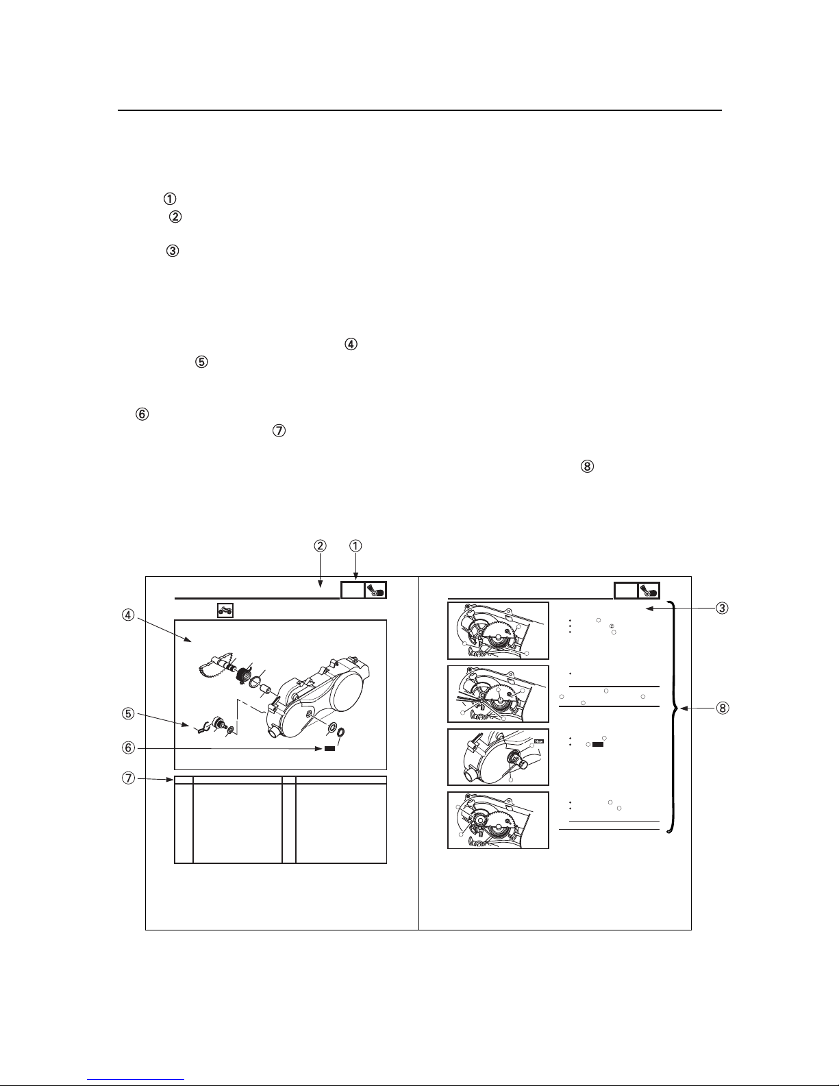
CHAPTER 3
PERIODIC CHECKS AND ADJUSTMENTS

ENGINE ...........................................................................................................4-1
EXHAUST PIPE/MUFFLER, BREATHER HOSE AND LEADS ................4-1
ENGINE MOUNTING BOLTS ...................................................................4-2
REMOVING THE ENGINE ........................................................................4-3
INSTALLING THE ENGINE.......................................................................4-3
CYLINDER HEAD ............................................................................................ 4-4
REMOVING THE CYLINDER HEAD.........................................................4-6
CHECKING THE CAMSHAFT SPROCKET..............................................4-7
CHECKING THE CYL. HEAD COVER ASSY............................................4-7
CHECKING THE TIMING CHAIN GUIDES...............................................4-7
CHECKING THE TIMING CHAIN TENSIONER ASSEMBLY ...................4-7
CHECKING THE CYLINDER HEAD .........................................................4-8
INSTALLING THE CYLINDER HEAD .......................................................4-9
CAMSHAFT, ROCKER ARMS AND VALVES ..............................................4-11
REMOVING THE ROCKER ARMS AND CAMSHAFT............................4-12
REMOVING THE VALVES AND VALVE SPRINGS ...............................4-12
CHECKING THE CAMSHAFT.................................................................4-13
CHECKING THE ROCKER ARMS AND ROCKER ARM SHAFTS ........4-13
CHECKING THE VALVES AND VALVE SPRINGS ................................4-15
INSTALLING THE VALVES AND VALVE SPRINGS ..............................4-19
INSTALLING THE CAMSHAFT AND ROCKER ARMS ..........................4-20
CYLINDER AND PISTON ..............................................................................4-21
REMOVING THE PISTON ....................................................................... 4-22
CHECKING THE CYLINDER AND PISTON ............................................4-22
CHECKING THE PISTON RINGS............................................................4-24
CHECKING THE PISTON PIN .................................................................4-25
INSTALLING THE PISTON ......................................................................4-26
INSTALLING THE CYLINDER .................................................................4-27
C.D.I. MAGNETO ........................................................................................... 4-28
REMOVING THE C.D.I. MAGNETO ROTOR ..........................................4-29
CHECKING THE PICKUP COIL/STATOR ASSEMBLY...........................4-29
INSTALLING THE C.D.I. MAGNETO ROTOR .........................................4-30
CHAPTER 4
ENGINE

BELT DRIVE ................................................................................................4-31
CRANKCASE COVER.............................................................................4-31
KICKSTARTER........................................................................................4-32
INSTALLING THE KICKSTARTER..........................................................4-33
V-BELT, CLUTCH, DRIVE AND DRIVEN PULLEY.................................4-34
DISASSEMBLING THE SECONDARY SHEAVE....................................4-35
REMOVING THE PRIMARY SHEAVE....................................................4-36
REMOVING THE SECONDARY SHEAVE AND V-BELT........................4-36
DISASSEMBLING THE SECONDARY SHEAVE....................................4-37
CHECKING THE CLUTCH SHOE...........................................................4-37
CHECKING THE V-BELT........................................................................4-38
CHECKING THE DRIVE PULLEY...........................................................4-38
CHECKING THE PRIMARY ROLLER WEIGHTS...................................4-38
CHECKING THE PIECE SLIDER............................................................4-39
CHECKING THE DRIVEN PULLEY........................................................ 4-39
ASSEMBLING THE PRIMARY SHEAVE................................................4-40
ASSEMBLING THE SECONDARY SHEAVE..........................................4-41
INSTALLING THE BELT DRIVE..............................................................4-42
TRANSMISSION ..........................................................................................4-55
CHECKING THE TRANSMISSION.........................................................4-56
CRANKCASE AND CRANKSHAFT ............................................................4-49
SEPARATING THE CRANKCASE..........................................................4-50
REMOVING THE CRANKSHAFT ASSEMBLY........................................4-51
CHECKING THE TIMING CHAIN AND TIMING CHAIN GUIDES...........4-51
CHECKING THE CRANKSHAFT AND CONNECTING ROD..................4-52
INSTALLING THE CRANKSHAFT..........................................................4-53
ASSEMBLING THE CRANKCASE..........................................................4-54
STARTER CLUTCH AND STARTER MOTOR ............................................4-44
CHECKING THE STARTER WHEEL GEAR...........................................4-45
OIL PUMP .....................................................................................................4-46
CHECKING THE OIL PUMP....................................................................4-47
INSTALLING THE OIL PUMP..................................................................4-48

CARBURETOR................................................................................................5-1
DISASSEMBLING THE CARBURETOR...................................................5-4
CHECKING THE CARBURETOR .............................................................5-4
ASSEMBLING THE CARBURETOR.........................................................5-6
INSTALLING THE CARBURETOR ...........................................................5-7
MEASURING AND ADJUSTING THE FUEL LEVEL ................................5-8
CHAPTER 5
CARBURETOR

FRONT AND REAR WHEELS ......................................................................6-1
FRONT WHEELS ....................................................................................6-1
REAR WHEELS ......................................................................................6-2
CHECKING THE WHEELS .....................................................................6-3
CHECKING THE FRONT WHEEL HUBS ...............................................6-3
CHECKING THE REAR WHEEL HUBS..................................................6-4
INSTALLING THE WHEEL HUBS...........................................................6-4
INSTALLING THE FRONT WHEELS......................................................6-5
INSTALLING THE REAR WHEELS........................................................ 6-5
FRONT BRAKES ..........................................................................................6-6
FRONT BRAKE S ....................................................................................6-6
REMOVING THE FRONT BRAKES .......................................................6-7
CHECKING THE FRONT BRAKE SHOE PLATES ................................6-7
CHECKING THE FRONT BRAKE SHOES..............................................6-7
CHECKING THE FRONT BRAKE DRUMS .............................................6-8
INSTALLING THE FRONT BRAKES ......................................................6-9
REAR AXLE AND REAR AXLE HUB...........................................................6-11
REAR AXLE AND REAR AXLE HUB......................................................6-11
REMOVING THE REAR AXLE...............................................................6-13
CHECKING THE REAR AXLE...............................................................6-14
CHECKING THE DRIVEN SPROCKET..................................................6-14
CHECKING THE BRAKE DISC................................................................6-14
INSTALLING THE DRIVEN SPROCKET.................................................6-14
INSTALLING THE REAR AXLE...............................................................6-15
REAR BRAKE ...............................................................................................6-16
REAR BRAKE PADS...............................................................................6-16
REPLACING THE REAR BRAKE PADS.................................................6-17
REAR BRAKE MASTER CYLINDER......................................................6-19
CHECKING THE MASTER CYLINDER...................................................6-20
ASSEMBLING THE REAR BRAKE MASTER CYLINDER......................6-20
INSTALLING THE REAR BRAKE MASTER CYLINDER.........................6-21
REAR BRAKE CALIPER..........................................................................6-23
REMOVING THE PARKING BRAKE CABLE..........................................6-25
CHECKING THE REAR BRAKE CALIPER.............................................6-25
INSTALLING THE REAR BRAKE CALIPER............................................6-26
CHAPTER 6
CHASSIS

STEERING SYSTEM .....................................................................................6-28
HANDLEBAR...........................................................................................6-28
REMOVING THE HANDLEBAR GRIPS..................................................6-30
REMOVING THE REAR BRAKE SWITCH .............................................6-30
CHECKING THE HANDLEBAR ..............................................................6-30
INSTALLING THE HANDLEBAR ............................................................ 6-31
INSTALLING THE HANDLEBAR GRIPS ................................................6-31
INSTALLING THE REAR BRAKE MASTER CYLINDER........................6-32
INSTALLING THE FRONT BRAKE LEVER ASSEMBLY........................6-32
INSTALLING THE PARKING BRAKE LEVER.........................................6-33
STEERING STEM ...................................................................................6-34
REMOVING THE STEERING STEM ...................................................... 6-35
CHECKING THE STEERING STEM .......................................................6-35
INSTALLING THE STEERING STEM .....................................................6-36
INSTALLING THE LOWER HANDLEBAR HOLDER...............................6-36
INSTALLING THE LOCK WASHER........................................................6-36
TIE-RODS AND STEERING KNUCKLES ...............................................6-37
REMOVING THE STEERING KNUCKLES..............................................6-38
REMOVING THE TIE-RODS...................................................................6-38
CHECKING THE TIE-RODS ...................................................................6-38
CHECKING THE STEERING KNUCKLES..............................................6-38
INSTALLING THE TIE-RODS .................................................................6-39
FRONT ARMS AND FRONT SHOCK ABSORBER ASSEMBLIES............. 6-40
REMOVING THE FRONT ARMS.............................................................6-41
FRONT ARMS AND FRONT SHOCK ABSORBER
ASSEMBLIES..........................................................................................6-40
CHECKING THE FRONT ARMS.............................................................6-41
CHECKING THE FRONT SHOCK ABSORBERS...................................6-41
CHECKING THE BALL JOINTS.............................................................. 6-42
INSTALLING THE FRONT ARMS............................................................6-42
REAR SHOCK ABSORBER, SWINGARM AND DRIVE CHAIN..................6-43
REAR SHOCK ABSORBER, SWINGARM AND DRIVE CHAIN.............6-43
REMOVING THE REAR SHOCK ABSORBER........................................6-45
CHECKING THE REAR SHOCK ABSORBER........................................6-45
REMOVING THE SWINGARM................................................................6-45
CHECKING THE SWINGARM.................................................................6-46
CHECKING THE DRIVE CHAIN..............................................................6-47
INSTALLING THE DRIVE SPROCKET................................................... 6-48
INSTALLING THE DRIVE CHAIN............................................................6-48

ELECTRICAL COMPONENTS........................................................................7-1
CHECKING THE SWITCHS ............................................................................7-3
WIRING DIAGRAM .........................................................................................7-2
CHECKING SWITCH CONTINUITY
.............................................................7-4
IGNITION SYSTEM .........................................................................................7-5
CIRCUIT DIAGRAM ..................................................................................7-5
TROUBLESHOOTING ..............................................................................7-6
ELECTRIC STARTING SYSTEM ..................................................................7-10
CIRCUIT DIAGRAM ................................................................................7-10
STARTING CIRCUIT OPERATION.........................................................7-11
TROUBLESHOOTING ............................................................................7-12
STARTER MOTOR........................................................................................7-14
CHECKING THE STARTER MOTOR .....................................................7-15
ASSEMBLING THE STARTER MOTOR.................................................7-16
CHARGING SYSTEM....................................................................................7-17
CIRCUIT DIAGRAM ................................................................................7-17
TROUBLESHOOTING ............................................................................7-18
CHAPTER 7
ELECTRICAL

STARTING FAILURE/HARD STARTING ....................................................... 8-1
FUEL SYSTEM..........................................................................................8-1
ELECTRICAL SYSTEM.............................................................................8-1
COMPRESSION SYSTEM........................................................................8-2
POOR IDLE SPEED PERFORMANCE ........................................................... 8-2
POOR IDLE SPEED PERFORMANCE.....................................................8-2
POOR MEDIUM AND HIGH-SPEED PERFORMANCE..................................8-2
POOR MEDIUM AND HIGH-SPEED PERFORMANCE ...........................8-2
FAULTY CLUTCH ...........................................................................................8-3
ENGINE OPERATES BUT VEHICLE WILL NOT MOVE..........................8-3
CLUTCH SLIPPING..................................................................................8-3
POOR STARTING PERFORMANCE........................................................8-3
POOR SPEED PERFORMANCE..............................................................8-3
OVERHEATING...............................................................................................8-3
OVERHEATING ........................................................................................8-3
FAULTY BRAKE .............................................................................................8-4
POOR BRAKING EFFECT........................................................................ 8-4
SHOCK ABSORBER MALFUNCTION ...........................................................8-4
MALFUNCTION.........................................................................................8-4
UNSTABLE HANDLING..................................................................................8-4
UNSTABLE HANDLING ............................................................................8-4
CHAPTER 8
TROUBLESHOOTING

GEN
INFO
GENERAL INFORMATION
MACHINE IDENTIFICATION
VEHICLE IDENTIFICATION NUMBER
The vehicle identification number is stamped
into the left side of the frame.
MACHINE IDENTIFICATION
1 - 1
The engine serial number is stamped on
the engine.
ENGINE SERIAL NUMBER
1

IMPORTANT INFORMATION
PREPARATION FOR REMOVAL AND
DISASSEMBLY
1.Before removal and disassembly add, remove
all dirt, mud, dust and foreign material.
2. Use only the proper tools and cleaning
equipment.
3. When disassembling always keep mated
parts together. This includes gears, cylin-
ders, pistons and other parts that have been
“mated” through normal wear. Mated parts
must always be reused or replaced as an
assembly.
4. During disassembly, clean all of the parts
and place them in trays in the order of dis-
assembly. This will speed up assembly and
allow for the correct installation of all parts.
5. Keep all parts away from any source of fire.
GASKETS, OIL SEALS AND O-RINGS
1. When overhauling the engine, replace all
gaskets, seals and O-rings. All gasket sur-
faces, oil seal lips and O-rings must be
cleaned.
2. During reassembly properly oil all mating
parts and bearings, and lubricate the oil
seal lips with grease.
1. Use only genuine E-TON parts for all
replacements.
REPLACEMENT PARTS
1 - 2
GEN
INFO
IMPORTANT INFORMATION

LOCK WASHERS/PLATES AND COTTER
PINS
After removal, replace all lock washers/plates
and cotter pins. After the bolt or nut has
been tightened to specification, bend the lock
tabs along a flat of the bolt or nut.
BEARINGS AND OIL SEALS
Install bearings and oil seals so that the manu-
facturer’s marks or numbers are visible. When
installing oil seals, lubricate the oil seal lips
with a light coat of lithium-soap-based grease.
Oil bearings liberally when installing, if appro-
priate.
Oil seal
Do not spin the bearing with compressed
air because this will damage the bearing
surfaces.
Bearing
CIRCLIPS
Before reassembly, check all circlips carefully
and replace damaged or distorted circlips.
Always replace piston pin clips after one use.
When installing a circlip , make sure the
sharp-edged corner is positioned opposite
the thrust that the circlip receives.
Shaft
1 - 3
GEN
INFO
IMPORTANT INFORMATION
რ
NOTICE

CHECKING THE CONNECTIONS
Check the leads, couplers, and connectors for
stains, rust, moisture, etc.
1. Disconnect:
• lead
• coupler
• connector
2. Check:
• lead
• coupler
• connector
Moisture Dry with an air blower.
Rust/stains Connect and disconnect sev-
eral times.
3. Check:
• all connections
Loose connection ĺ
ĺ
ĺ
Connect properly.
If the pin 1on the terminal is flattened, bend it
up.
4. Connect:
• lead
• coupler
• connector
Make sure all connections are tight.
5. Check:
• continuity (with the pocket tester)
• If there is no continuity, clean the terminals.
• When checking the wire harness, perform
steps (1) to (3).
• As a quick remedy, use a contact revitalizer
available at most part stores.
1 - 4
GEN
INFO
IMPORTANT INFORMATION
TIP
TIP
TIP
This manual suits for next models
1
Table of contents
Other Eton Offroad Vehicle manuals

Eton
Eton VIPER 50M User manual

Eton
Eton 2006 Viper 70 User manual

Eton
Eton DXL90 User manual

Eton
Eton Vector 250R User manual

Eton
Eton Viper 40E (RXL-40E) User manual

Eton
Eton Vector 250R User manual

Eton
Eton VECTOR ST 250 User manual

Eton
Eton IXL 40 User manual

Eton
Eton Viper 70 User manual

Eton
Eton VIPER 50 ST - SERVICE User manual

Eton
Eton Yukon II User manual

Eton
Eton Yukon II CXL-150 User manual

Eton
Eton ATV3F-150 - SERVICE User manual

Eton
Eton Lightning-AXL50 User manual

Eton
Eton CXL-150 User manual

Eton
Eton ATV8E - SERVICE User manual

Eton
Eton ATV RXL 50 User manual

Eton
Eton ATV8F - SERVICE User manual

Eton
Eton Viper Jr. (RXL-40) User manual

Eton
Eton ROVER User manual