ETS-Lindgren EMI Manual

EMI-EMP Filter
Signal / Control / Data
Installation and Maintenance Manual
1703315 Rev CDecember 2019


3
ETS-Lindgren Inc. reserves the right to make changes to any products herein to improve functioning or design.
Although the information in this document has been carefully reviewed and is believed to be reliable, ETS-Lindgren
does not assume any liability arising out of the application or use of any product or circuit described herein; nor does
it convey any license under its patent rights nor the rights of others. All trademarks are the property of their respective
owners.
© Copyright 2019 by ETS-Lindgren Inc. All Rights Reserved. No part of this document may be copied by any
means without written permission from ETS-Lindgren Inc.
Trademarks used in this document: The ETS-Lindgren logo is a registered trademark of ETS-Lindgren, Inc.
Revision Record
MANUAL,EMI-EMP Filter | Part # 1703315 Rev C
Revision Description Date
AInitial Release April, 2019
BUpdated September, 2019
CNote added to Maintenance section December, 2019

4

5
TABLE OF CONTENTS
NOTES, CAUTIONS AND WARNINGS 7
SAFETY INFORMATION 7
GENERAL SAFETY CONSIDERATIONS 8
INTRODUCTION 9
ETS-Lindgren Product Information Bulletin . . . . . . . . . . . . . . . . . . . . . . . . . . . . 9
PRECAUTIONS 9
FILTER COMPONENTS 10
Filter Elements . . . . . . . . . . . . . . . . . . . . . . . . . . . . . . . . . . . . . . . 10
Terminations . . . . . . . . . . . . . . . . . . . . . . . . . . . . . . . . . . . . . . . . 10
Input . . . . . . . . . . . . . . . . . . . . . . . . . . . . . . . . . . . . . . . . . . 10
Output. . . . . . . . . . . . . . . . . . . . . . . . . . . . . . . . . . . . . . . . . . 10
Filter Penetrations . . . . . . . . . . . . . . . . . . . . . . . . . . . . . . . . . . . . . . 10
MOV Failure and Protective Devices (If Provided) . . . . . . . . . . . . . . . . . . . . . . . . . . 10
Automatic Discharge . . . . . . . . . . . . . . . . . . . . . . . . . . . . . . . . . . . . . 10
Shorting Stick (Not Provided) . . . . . . . . . . . . . . . . . . . . . . . . . . . . . . . . . . 11
ELECTRICAL PERFORMANCE CHARACTERISTICS 11
Voltage (RMS) . . . . . . . . . . . . . . . . . . . . . . . . . . . . . . . . . . . . . . . 11
Voltage Drop . . . . . . . . . . . . . . . . . . . . . . . . . . . . . . . . . . . . . . . . 11
Overload Current . . . . . . . . . . . . . . . . . . . . . . . . . . . . . . . . . . . . . . 11
Insertion Loss (Stop Band) . . . . . . . . . . . . . . . . . . . . . . . . . . . . . . . . . . . 11
Current . . . . . . . . . . . . . . . . . . . . . . . . . . . . . . . . . . . . . . . . . . 11
Frequency of Operation (Pass Band) . . . . . . . . . . . . . . . . . . . . . . . . . . . . . . . 11
ENVIRONMENTAL SPECIFICATIONS 12
INSTALLATION 12
POWER ON 12
MAINTENANCE 13
Inspection and Cleaning of Wiring Compartments . . . . . . . . . . . . . . . . . . . . . . . . . . 13
Capacitance Measurement and MOV Inspection Voltage . . . . . . . . . . . . . . . . . . . . . . . 14
If no Transient Protection is provided the sections pertaining to MOVs do not apply. 14

6
ILLUSTRATIONS 15
Filter Penetration . . . . . . . . . . . . . . . . . . . . . . . . . . . . . . . . . . . . . . 15
Filter Installation on Shield . . . . . . . . . . . . . . . . . . . . . . . . . . . . . . . . . . . 16
Filter Electrical Wiring . . . . . . . . . . . . . . . . . . . . . . . . . . . . . . . . . . . . . 16
Individually Mounted Filters . . . . . . . . . . . . . . . . . . . . . . . . . . . . . . . . . 16
Panelized Filters . . . . . . . . . . . . . . . . . . . . . . . . . . . . . . . . . . . . . 16
WARRANTY STATEMENT 21

7
NOTES, CAUTIONS AND WARNINGS
Note: Denotes helpful information intended to provide tips for better use of
the product.
Caution: Denotes a hazard. Failure to follow instructions could result in
minor personal injury and/or property damage. Included text gives proper
procedures.
Warning: Denotes a hazard. Failure to follow instructions could result in
SEVERE personal injury and/or property damage. Included text gives proper
procedures.
SAFETY INFORMATION
Refer to Manual: When product is marked with this symbol, see the
instruction manual for additional information. If the instruction manual has
been misplaced, download it from www.ets-lindgren.com, or contact
ETS-Lindgren Customer Service.
High Voltage: Indicates presence of hazardous voltage. Unsafe practice
could result in severe personal injury or death.
High Voltage: Indicates presence of hazardous voltage. Unsafe practice
could result in severe personal injury or death.
Protective Earth Ground (Safety Ground): Indicates protective earth
terminal. You should provide uninterruptible safety earth ground from the
main power source to the product input wiring terminals, power cord, or
supplied power cord set.
See the ETS-Lindgren Product Information Bulletin for safety, regulatory, and other product
marking information.

8
GENERAL SAFETY CONSIDERATIONS
Before power is applied to this instrument, ground it properly through the
protective conductor of the AC power cable to a power source provided with
the protective earth contact. Any interruption of the protective (grounding)
conductor, inside or outside the instrument, or disconnection of the protective
earth terminal could result in personal injury.
Before servicing: contact ETS-Lindgren – servicing (or modifying) the unit by
yourself may void your warranty. If you attempt to service the unit by yourself,
disconnect all electrical power before starting. There are voltages at many
points in the instrument which could, if contacted, cause personal injury.
Only trained service personnel should perform adjustments and/or service
procedures upon this instrument. Capacitors inside this instrument may still
be CHARGED even when instrument is disconnected from its power source.
Only qualied personnel should operate (or service) this equipment.
WARRANTY

9
INTRODUCTION
ETS-Lindgren Filters are electromagnetically isolated Electromagnetic Interference (EMI) Filter enclosures with EMI
isolated lter components. Filters designated as -TS are equipped with transient protection devices (MOVs). The lter is
designed to lter internally and externally generated EMI conducted emissions and arrest high transient currents when
equipped with MOVs.
ETS-Lindgren Product Information Bulletin
See the ETS-Lindgren Product Information Bulletin included with your shipment for the following:
• Warranty information
• Safety, regulatory, and other product marking information
• Steps to receive your shipment
• Steps to return a component for service
• ETS-Lindgren calibration service
• ETS-Lindgren contact information
PRECAUTIONS
LETHAL VOLTAGES PRESENT. THIS UNIT SHOULD BE INSTALLED AND MAINTAINED BY A
QUALIFIED ELECTRICIAN.
AUTOMATIC BLEEDER RESISTORS DISCHARGE THE CAPACITORS TO 50 V FIVE (5)
SECONDS AFTER POWER IS REMOVED.
USE A SHORTING STICK (NOT INCLUDED) TO TOUCH ALL EXPOSED METAL SURFACES
PRIOR TO TOUCHING THE FILTER.

10
FILTER COMPONENTS
Filter Elements
The lter consists of lter components enclosed in a lter can and termination connections. If the lter is equipped
with Transient Protection, there will also be MOVs in the lter.
There are NO USER SERVICEABLE PARTS inside the Filter.
Should a lter be determined to be defective, contact ETS-Lindgren to order a replacement or to schedule its return
or replacement.
Terminations
Input
Only qualied personnel should operate or service this equipment.
The source conductors are brought through an opening made in the eld on the dirty side wiring compartment of
the lter. The opening should be of sucient diameter to allow the free passage of conductors. The conductors
should then be directly terminated to the lter terminals or lugs (if provided), or equivalent.
Output
The output conductors are brought into the clean side wiring compartment of the lter through a conduit
penetration (if provided) or a circular opening in the back of the lter panel. The conductors should then be directly
terminated to the lter terminals or lugs (if provided), or equivalent.
The output terminals of the lter are EMI isolated from the inputs.
Filter Penetrations
All lter penetrations include attached conductive elastomeric gaskets to maintain shielding eectiveness and
environmental seal.
MOV Failure and Protective Devices (If Provided)
The prime power circuit breaker upstream from the lter and MOV protector should provide overcurrent protection.
This minimizes the possibility of undetected loss of transient protection (if provided).
Automatic Discharge
Some signal lters contain bleeder resistors that will automatically reduce the voltage on any component after the
removal of input power. Contact ETS-Lindgren for details. Always discharge lters as described in the SHORTING
STICK section of this manual.

11
Shorting Stick (Not Provided)
Only qualied personnel should operate or service this equipment.
A shorting stick (grounding rod) should be used by qualied service personnel to ensure all capacitors and other
energy storage elements are discharged and in a safe state. All terminals accessible to service personnel and
capable of retaining stored energy in the event of automatic discharge circuit failure are accessible and should be
shorted to ground with a shorting stick or equivalent.
ELECTRICAL PERFORMANCE CHARACTERISTICS
Voltage (RMS)
According to lter label, as applicable to each individual lter type.
Voltage Drop
The total AC voltage drop from input to output is designed to be no more than 2% of the rated voltage when
measured into a unity power factor.
Overload Current
The lter can withstand an overload current of 1.4 times the rated current in amperes for a period of fteen (15)
minutes and maintain ltering during this period per MIL-F15733.
Insertion Loss (Stop Band)
As applicable to each individual lter type per MIL-STD-220.
Current
According to lter label, as applicable to each individual lter type.
Frequency of Operation (Pass Band)
According to lter label, as applicable to each individual lter type.

12
ENVIRONMENTAL SPECIFICATIONS
Attribute Operating Non-Operating
Temperature -45° C to + 65° C -55° C to +85° C
Altitude Sea Level to 8,000 ft Sea level to 40,000 ft
Humidity Relative humidity between 10% and
90% at air temperatures between
+25° C and +32° C
Relative humidity as low as 14% at an
air temperature of +71° C and as high
as 100% at temperatures from -33°
C to +33° C with condensation at all
temperatures lower than +30° C
INSTALLATION
Uncrate all parts. Check all parts for any shipping damage. Ensure adequate space is available for installing the lter.
Do not discard any packaging material until the unit is installed.
Electrical connection should only be performed by a qualied electrician and in compliance with all
applicable regulatory agencies.
Connection to the lter should be made by qualied electricians. Refer to the TERMINATIONS section for
further details.
Wiring should be done in accordance to the wiring schematic provided in the ILLUSTRATIONS section of this manual
and applicable local and national electrical codes and guidelines.
Installation of the conduit penetration and EMI gasket should be done in accordance with the drawing provided in the
ILLUSTRATIONS section of this manual.
POWER ON
Prior to applying power to the lter, verify wiring is correct. Use an ohmmeter to verify there are no shorts
from any line to ground or neutral.
Electrical wiring verication should only be performed by a qualied electrician and in compliance
with all applicable regulatory agencies.

13
MAINTENANCE
LETHAL VOLTAGES PRESENT. RISK OF ELECTRIC SHOCK.
AFTER REMOVING POWER FROM THE UNIT, THE AUTOMATIC BLEEDER RESISTORS WILL
DISCHARGE THE UNIT TO 50 V IN FIVE (5) SECONDS.
USE A SHORTING STICK (NOT INCLUDED) TO TOUCH ALL METALLIC SURFACES
EXPOSED BEFORE TOUCHING THE FILTER.
Only qualied personnel should operate or service this equipment.
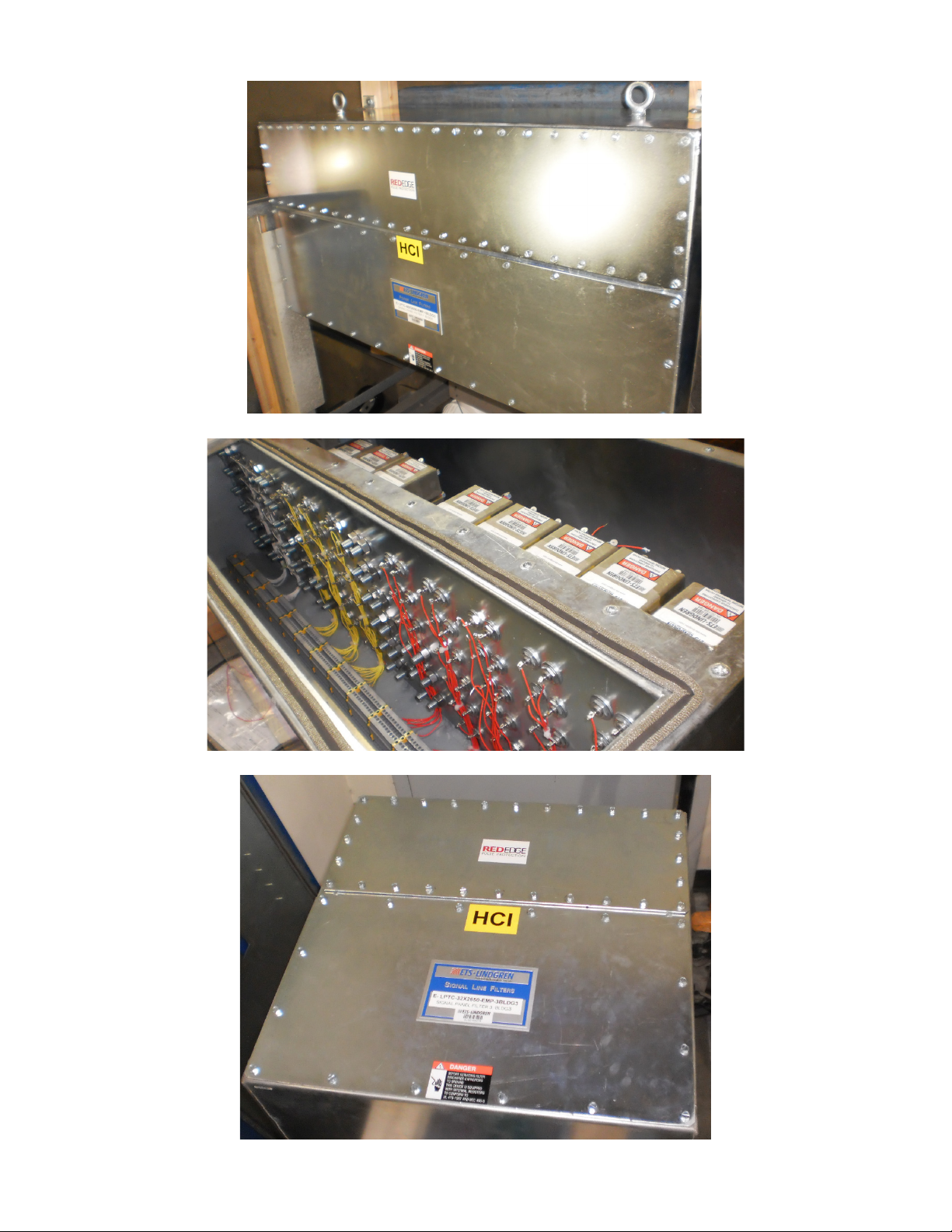
Periodically power down the lter and remove the wiring compartment lids to check inside for dirt, debris and corrosion.
Oil, dirt, debris and corrosion inside the lter compartments should be removed according to appropriate procedures.
User’s own procedures for the removal of spills, dirt, debris and corrosion should suce. Should EMI gasket become
torn or unusable, contact ETS-Lindgren to order replacement part E-903-008 or E-903-016, depending on the
size of lter.
The MOV arrestor (if provided) should be replaced annually, when it is estimated that a high incidence of over voltages
have occurred during that year.
Once a lter is properly installed it typically does not require maintenance under normal operating conditions. However,
if there is an extraordinary event aecting the lters (such as a severe voltage overload or water entering the wiring
compartments), then the following procedures should be followed depending on the nature of the event. Follow the
INSPECTION AND CLEANING OF WIRING COMPARTMENTS procedure after an event that causes abnormal
contamination of lter wiring compartments with liquid or debris. Follow the CAPACITANCE MEASUREMENT AND
MOV INSPECTION PROCEDURE following an event that causes abnormal voltage overloads or spikes beyond that
which the lters are designed to accommodate.
Frequency of maintenance is at the discretion of the user and may be included in a routine maintenance
schedule for the connected equipment. However, lters in clean, industrial environments typically do not
require maintenance.
Inspection and Cleaning of Wiring Compartments
1. Remove power from the lter(s).
2. Wait at least sixty (60) seconds, then remove the wiring compartment covers.
3. Short the lter terminals to the lter case using a conductive shorting stick (not included) to ensure that the lter
capacitors are fully discharged.
4. Inspect the lter terminals and insulators for contamination and/or damage.
5. If the terminals or insulators are cracked or damaged replacement in the eld is not possible.
Call ETS-Lindgren for instructions.
6. Clean the terminals and insulators as necessary, and remove any loose debris from the wiring compartments.
7. Re-install the wiring compartment covers. Ensure even compression of the RF gasket around the RF tight
wiring compartment. Begin by torquing all of the cover screws to 1 N-m, starting in the center of each ange
and working out towards the corners. Then, using the same pattern torque all screws to 5 N-m.
8. Re-apply power to the lter(s).

14
Capacitance Measurement and MOV Inspection Voltage
If no Transient Protection is provided the sections pertaining to MOVs do not apply.
1. Remove power from the lter(s).
2. Wait at least sixty (60) seconds, then remove the wiring compartment covers. Use a voltmeter to ensure no
voltage is present.
3. Short the lter terminals to the lter case using a conductive shorting stick (not included) to ensure that lter
capacitors are fully discharged.
4. Disconnect the phase and neutral electrical wiring from the electrical termination points.
5. Inspect the lter terminals and insulators for contamination and/or damage.
6. If any of the terminals or insulators are cracked or damaged replace the damaged component in accordance
with the directions provided with the replacement parts.
7. Inspect the MOVs (when provided) for damage.
8. If any MOVs are damaged, replace the damaged component in accordance with the directions provided with
the replacement parts.
9. Measure MOVs with a Bourns Model 4030-01 (or equivalent) to determine if they are operational. Replacement
is required if they are not operational.
10. Measure the line to ground capacitance of each phase. Using an LCR bridge measure the capacitance of each
phase at 120 Hz. Contact ETS-Lindgren for expected values (please provide model number of lter). The
reading should be according to these values ±20%. A DF measurement should be done at the same time and
recorded. DF readings above 0.08 should be noted and ETS-Lindgren should be called for advice before re-
applying power to the lter.
11. Clean the terminals and insulators as necessary, and remove any loose debris from the wiring compartments.
12. Re-install the phase and neutral electrical wiring to the electrical termination points. Torque the bolts and/or
nuts to the specied torque as noted next to the termination point.
13. Re-install the wiring compartment covers. Ensure even compression of the RF gasket around the RF tight
wiring compartment. Begin by torquing all of the cover screws to 1 N-m, starting in the center of each
ange and working out towards the corners. Then using the same pattern torque all screws to 5 N-m.
14. Re-apply power to the lter(s).

15
ILLUSTRATIONS
Filter Penetration
Filter penetrations should be installed as shown

16
Filter Installation on Shield
Filter Electrical Wiring
Individually Mounted Filters
Most lters provided will have solder-on terminals. Connection should be made by soldering an appropriately
sized conductor to the terminal. Soldering iron should not exceed 60W. An input terminal corresponds to an
output terminal on the same line.
Panelized Filters
These lters will be pre-wired to a set of DIN terminals on rails at the bottom of the cabinet/panel. Connection is
made to the DIN terminals by means of screwing a wire to them. Yellow/Green DIN terminals are
grounded points.
Installation on shield is straight forward as shown

17
General illustration of an individually mounted signal lter
General illustration of a signal line panel lter

18
Individually mounted 4-line signal lter
Individually mounted 2-line signal lter

19
Panel signal lter
Individually mounted 10 to 12-line signal lter

20
This manual suits for next models
1
Table of contents
Other ETS-Lindgren Water Filtration System manuals
Popular Water Filtration System manuals by other brands

Pall
Pall UT310 Series Service instructions

Veolia
Veolia HYDROTECH 12 Series Operation and maintenance manual

IONFILTER
IONFILTER ALISON user manual

Pentair
Pentair EVERPURE ENDURANCE EV943730 Installation, operation, maintenance guide

Clean Water Systems
Clean Water Systems Tannin 5900e Series Installation & start?up guide

HOMBLI
HOMBLI HEPA 13 Filter manual