ETS 5504 User manual

www.electrotechsystems.com 833-ENV-GURU (833-368-4878) D01833 Revision A –20211101 - Page 2of 24
Table of Contents
I. Important Safety Information ........................................................3
II. Description of Contents...............................................................5
III. Set-Up Guide..............................................................................8
Part 1: Chamber Unpacking and Initial Setup............................................................ 8
Part 2: Operating System Setup................................................................................ 9
Part 2a. Controller: Model 5000-Series Microcontroller with 556 Sensor ......................................9
Part 2b. Heating & Cooling: Model 5475-250 Thermoelectric Heating/Cooling System ................9
Part 2c. Humidification: Model 5482 Ultrasonic Humidifier.........................................................10
Part 2d. Dehumidification Systems.............................................................................................13
IV. Quick Start Guide.....................................................................17
V. Functionality..............................................................................18
VI. Specifications...........................................................................20
VII. Repair and Maintenance.........................................................22
Calibration...............................................................................................................22
Preventive Maintenance..........................................................................................22
Repair.....................................................................................................................23
VIII. Warranty.................................................................................24
Revision History:
Revision A: Released 2021-11-01. Initial release
Products described in this manual are designed and assembled in the U.S.A. by
Electro-Tech Systems, Inc.
700 West Park Avenue
Perkasie, PA 18944

www.electrotechsystems.com 833-ENV-GURU (833-368-4878) D01833 Revision A –20211101 - Page 3of 24
I. Important Safety Information
This symbol accompanied by the
word “WARNING” calls attention to
an act or a condition which can
lead to serious personal injury or
death of operators and bystanders.
This symbol accompanied by the
word “CAUTION” indicates a
potentially hazardous situation
which, if not avoided, may result in
minor or moderate injury. The
symbol without any warning text
indicates potential damage to
device when misused.
This symbol indicates the presence
of hazardous AC or DC voltages
constituting the risk of electric
shock.
This symbol indicates a risk of fire
due to improper handling or failure
of device. For continued protection
against risk of fire, when replacing
fuses use only fuses of the
specified type and current ratings.
This symbol indicates the danger
of an electro-static discharge to
which equipment may be sensitive.
Observe all precautions for
handling electrostatic sensitive
devices.
These symbols indicate extreme
temperature which can cause
burns or frostbite. Avoid contact
with surface. Failure to follow
precautions may result in moderate
to severe injury.
SAFETY INSTRUCTIONS
The equipment described in this manual is designed and manufactured to operate within defined
design limits. Any misuse may result in electric shock or fire. To prevent the equipment from being
damaged, the following rules should be observed for installation, use and maintenance. Read the
following safety instructions before operating the instrument.

www.electrotechsystems.com 833-ENV-GURU (833-368-4878) D01833 Revision A –20211101 - Page 4of 24
POWER
POWER CORD: Use only the power cord specified for this equipment and certified for the country
of use. If the power (mains) plug is replaced, follow the wiring connections specified for the country
of use. When installing or removing the power plug, hold the plug, not the cord.
GROUNDING: The power cord provided is equipped with a 3-prong grounded plug (a plug with
a third grounding pin). This is both a safety feature to avoid electrical shock and a requirement
for correct equipment operation. If the outlet to be used does not accommodate the 3-prong plug,
either change the outlet or use a grounding adapter.
FUSES: Replace fuses only with those having the required current rating, voltage, and specified
type such as normal blow, time delay, etc. DO NOT use makeshift fuses or short the fuse holder.
This could cause a shock or fire hazard or severely damage the instrument.
OPERATION CAUTION
DO NOT OPERATE WITH COVERS OR PANELS REMOVED. Voltages inside the equipment
consist of line (mains) that can be anywhere from 100-240VAC.
DO NOT OPERATE WITH SUSPECTED EQUIPMENT FAILURES. If any odor or smoke becomes
apparent turn off the equipment and unplug it immediately. Failure to do so may result in electrical
shock, fire, or permanent damage to the equipment. Contact the factory for further instructions.
DO NOT OPERATE IN AN EXPLOSIVE ATMOSPHERE. Operating the equipment in the
presence of flammable gases or fumes constitutes a definite safety hazard. For equipment
designed to operate in such environments the proper safety devices must be used such as dry air
or inert gas purge, intrinsic safe barriers and/or explosion-proof enclosures.
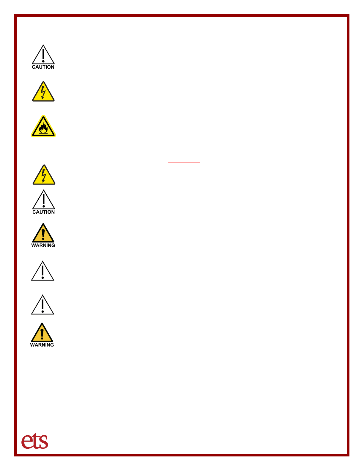
DO NOT IMPEDE THE CHAMBER FROM VENTING EXCESS PRESSURE. Available
dehumidification systems include open loop systems that pump external air into the chamber. If
the chamber is not allowed to vent, pressure can build up and cause serious damage to the
chamber.
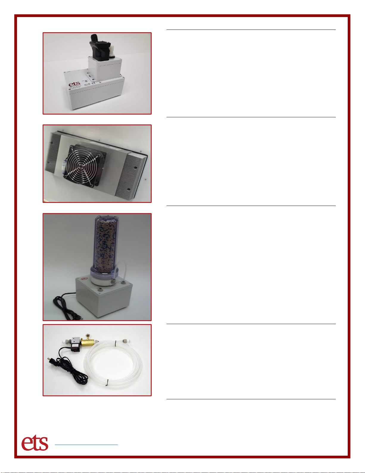
USE DISTILLED OR DEIONIZED WATER SOURCE FOR HUMIDIFICATION. Build-up of
contaminates on the transducer will cause stress to the transducer and electronics and resulting in
premature failure and invalidate the warranty.
DO NOT USE IN ANY MANNER NOT SPECIFIED OR APPROVED BY THE MANUFACTURER.
Unapproved use may result in damage to the equipment or present an electrical shock or fire
hazard.

www.electrotechsystems.com 833-ENV-GURU (833-368-4878) D01833 Revision A –20211101 - Page 5of 24
II. Description of Contents
Item
Description
Environmental Chamber
The Model 5504 is an acrylic (Plexiglas) chamber with
dimensions of 24” W x 18” D x 15” H. The chamber features an
18” x 12” door opening and non-setting gasket. It is constructed
of both clear and white acrylic for enhanced visibility and
contrast. The chamber can be purchased with or without front
glove ports.
Compatible Operating Systems available for additional purchase and integration include:
Model 5000-Series Controller and 556 Sensor
The Model 5000-Series Microcontroller is a separate
unit that utilizes PID control systems to create and hold
environmental conditions. The controller monitors
temperature and humidity with the Model 556 Sensor
and powers relevant operating systems to reach
desired conditions.

www.electrotechsystems.com 833-ENV-GURU (833-368-4878) D01833 Revision A –20211101 - Page 6of 24
Model 5482 Ultrasonic Humidifier
The Model 5482 ultrasonic humidifier is a separate unit
which sits outside the chamber. The humidifier accepts
distilled or deionized water from a water line or tank and
generates humidity on demand to humidify up to 95%
RH*. A water tank and tubing are included for use in
either open-loop or closed-loop configurations.
Model 5475-250 Thermoelectric Heater & Cooler
The Model 5475-250 Thermoelectric Heating and
Cooling system provides a complete temperature
solution. Utilizing Peltier elements and air-to-air
conditioning, the Model 5475-250 can maintain
temperatures from 10°C to 60°C at ambient conditions*.
A universal voltage power supply and thermal channel
controller are included.
Model 5461 Molecular Sieve Dehumidifier
The Model 5461 Molecular Sieve Desiccant Column is
a separate unit which sits outside of the chamber. It
utilizes renewable indicating desiccant in a closed-loop
configuration to dehumidify to at least 10% RH*. Tubing
is included. 115V or 230V Voltage requirements must
be specified.
Model 5465 Dry Nitrogen Gas Dehumidifier
The Model 5465 Dry Nitrogen Valve is a separate unit
which attaches to the chamber. It requires a customer
supply of nitrogen gas to dehumidify to as low as 5%
RH* and includes an over-pressure protection module.
The Model 5465 operates in an open-loop
configuration. Tubing is included.
*Temperature and Humidity range is valid for the M 5504 chamber with an ambient temperature of 22°C ±3°C and relative humidity of 25% to
70% RH. Lower humidities down to 2-5% RH can be achieved with increased temperatures and/or extended conditioning times.

www.electrotechsystems.com 833-ENV-GURU (833-368-4878) D01833 Revision A –20211101 - Page 7of 24
Model 5478 Regenerative Desiccant Dehumidifier
The Model 5478 Self-Regenerating Dehumidifier is a
separate unit which sits outside of the chamber. It
utilizes a dual-column desiccant recharging mechanism
to dehumidify as low 5% RH* without need for
maintenance and includes an over-pressure protection
module. Operates in an open-loop configuration and
requires 50-100 psi house air. Tubing is included. 115V
or 230V Voltage requirements must be specified.
Gloves
A pair of rubber gloves for installation in the chamber 6”
glove ports.
*Temperature and Humidity range is valid for the M 5504 chamber with an ambient temperature of 22°C ±3°C and relative humidity of 25% to 70% RH.
Lower humidities down to 2-5% RH can be achieved with increased temperatures and/or extended conditioning times.
Visit www.electrotechsystems.com for more.

www.electrotechsystems.com 833-ENV-GURU (833-368-4878) D01833 Revision A –20211101 - Page 8of 24
III. Set-Up Guide
Part 1: Chamber Unpacking and Initial Setup
Step 1-1
Step 1-2
Step 1-3
Note: DO NOT use any of
the chamber fittings or the
glove ports as a grip or for
leverage. Lift the chamber by
gripping around the outside of the
chamber.
Unpack the Main Chamber Unit and
inspect for visible damage. If no
damage is observed, then proceed to
the next step.
Place the chamber on a clean, level
bench area. If ordered with gloves,
verify gloves are secured firmly to the
chamber ports.
If the unit was ordered with
a heating/cooling unit
installed, it is
recommended to allow for at least 6
inches of open space behind the
chamber. Insufficient ventilation will
impact heating and cooling
performance.
Unpack the accessories and
applicable operating systems
shipped with the chamber.
Operating System connections are
located on the left side of the
chamber. Place operating systems
near the connections.
Sensor Input
Humidifier Output
Humidifier Return
Dehumidifier Output
Dehumidifier Return
Removeable Hole Plug
Step 1-4
Refer to above image and table for color-coded operating system input locations and descriptions. Color codes are
also listed alongside compatible operating systems in Section II. Description of Contents. Your chamber will only
feature relevant color indicators for purchased operating systems.
TOOLS NEEDED:

www.electrotechsystems.com 833-ENV-GURU (833-368-4878) D01833 Revision A –20211101 - Page 9of 24
Part 2: Operating System Setup
Part 2a. Controller: Model 5000-Series Microcontroller with 556 Sensor
Step 2a-1
Step 2a-2
Step 2a-3
Place the controller in an accessible,
convenient location. Ensure all front
panel switches are in the off position
(0).
On the rear of the controller unit,
ensure the “POWER” switch is in the
off position (0).
Plug the 556 Sensor cable into the
“SENSOR” jack.
Note: Plugging in the 556
sensor while the controller
is powered on may result in
damage to the sensor.
Connect the included AC power cord
receptacle into the “POWER IN” jack
and the plug into a standard outlet.
Ensure the sensor and its cable are
firmly connected.
Locate the sensor cord grip fitting on
the left chamber wall. It features the
GREEN color-indicator ring.
Loosen the fitting from the inside of
the chamber and insert the 556
sensor from the outside.
Tighten the fitting from the
inside to secure the sensor
in place. Tighten by hand
only, DO NOT use tools.
Part 2b. Heating & Cooling: Model 5475-250 Thermoelectric Heating/Cooling System
Step 2b-1
Step 2b-2
Step 2b-3
The Model 5475-250 Thermoelectric
Heating and Cooling system will be
mounted to the chamber if ordered.
The system consists of three
components –the Thermoelectric
(1), the Power Supply (2), and the
Thermal Channel Controller (3).
These will be mounted and
accessible on the rear of the
chamber.
On the rear of the chamber, perform
a quick visual check for any
disconnected wires.
Locating the Thermal Channel
Controller (3), plug the connector on
the dual-wall adapter cable into the
side of the unit.
Plug the wall adapters from the
Thermal Channel Controller (1) into
the rear of the Model 5000-Series
Controller unit.
Plug the wall adapter plug labeled
“COOL” into the controller “COOL”
socket.
Plug the wall adapter plug labeled
“HEAT” into the controller “HEAT”
socket.

www.electrotechsystems.com 833-ENV-GURU (833-368-4878) D01833 Revision A –20211101 - Page 10 of 24
Step 2b-4
Step 2b-5
Locating the Power Supply (2), plug
the AC power cable from the Power
Supply into a standard wall outlet.
The thermoelectric fans will turn on
after a few seconds.
Note: The thermoelectric fans act as
circulation fans for the system and
will be on at all times during use. The
system will only heat and cool upon
demand.
After verifying the fans turn on, the
power cord may be unplugged from
the AC outlet until the entire setup is
complete and the chamber is
intended to be used.
Part 2c. Humidification: Model 5482 Ultrasonic Humidifier
Step 2c-1
Step 2c-2
Step 2c-3
If ordered, the Model 5482 Ultrasonic
Humidifier system is supplied as a
standalone unit.
The system consists of a humidifier
unit, a 5-gallon water tank, a 10 ft
length of 1/4" OD semi-flexible
polyethylene tubing, and two 1-1/2 ft
lengths of 1” ID flexible PVC tubing.
Remove the top cap of the water tank
to reveal the spigot attachment.
Unscrew the spigot to separate the
attachment from the cap.
Hand-tighten the spigot
attachment onto water
tank. DO NOT use any
tools, over-tightening the cap will
damage the gasket and cause water
leakage.
Ensure the water tank tap lever is
pointed right in the “OFF” position,
as depicted.

www.electrotechsystems.com 833-ENV-GURU (833-368-4878) D01833 Revision A –20211101 - Page 11 of 24
Step 2c-4
Step 2c-5
Step 2c-6
Fill the tank to intended level, up to
five gallons, with de-ionized or
distilled water only. Hand-tighten the
top cap back onto the tank.
Note: Use of tap water will
cause build-up of
contaminates and cause
stress to the mist-generating
elements, which may result in
premature failure
Place water tank at a height above
the humidifier.
Insert 1/4” OD semi-rigid tubing firmly
into the “DEIONIZED WATER IN”
port on the humidifier.
Cut the tubing to length and insert the
other end into the water tank spigot
fitting.
Test the connections by gently
tugging on the tubing.
Optionally, utilize a water
line in place of the water
tank. Water line pressure
cannot exceed 50 psi.
Ensure the drain valve on the
humidifier unit is set to the “OFF”
position with the tap lever turned 90°
from the drain valve.
Ensure humidifier is placed
on a level surface with no
more than 5° tilt.
Step 2c-7
Step 2c-8
Step 2c-9
Ensure water supply tube is fully
inserted on both ends.
Loosen the small white cap on the
water tank top cap to allow water to
flow freely.
Switch the water tank tap lever to the
“ON” position (to the left) for water to
begin flowing.
Apply power to begin filling the water
basin. Plug the humidifier three-prong
AC line cord into a standard wall
outlet to test the functionality of the
humidifier.
The humidifier LED turns red while
the water fills the unit to an
acceptable level. This process should
take between 1 to 2 minutes.
After the water reaches an
acceptable level, the LED will turn
green to indicate system has enough
water to produce humidity.
Mist will begin to be produced and
will ooze out of the white barb on the
top of the unit.
Unplug the humidifier from the wall
outlet.

www.electrotechsystems.com 833-ENV-GURU (833-368-4878) D01833 Revision A –20211101 - Page 12 of 24
Step 2c-10
Step 2c-11
Step 2c-12
Concluding the humidifier function
test, plug the three-prong humidifier
AC line cord into the “HUMIDIFY”
socket on the rear of the controller.
Locate the two barb fittings on the
top-left of the left chamber wall. The
barbs are inverted to protect during
shipping and must be reversed.
Unscrew the two locknuts and swap
the direction of the fittings so that the
barbs face outward.
Tighten the set of barbs and locknuts
by hand until secured.
Ensure the Light Blue/Cyan color-
indicator ring is on the barb closer to
the rear of the chamber.
Ensure the Blue color-indicator ring
is on the barb closer to the front door
of the chamber.
Remove the rubber caps from the
chamber barbs and set aside.
Step 2c-13
Step 2c-14
Connect the two 1.5-foot sections of
1” ID flexible tubing to the humidifier.
Connect one tube to the white
humidity output barb. The humidity
output barb features a Blue color-
indicator washer.
Connect the other tube to the black
air inlet barb. The inlet barb features
a Light Blue/Cyan color-indicator
washer.
Connect the other ends of the tubing
to the corresponding chamber input
and return barbs. Match the colors
from output/inlet on the unit to the
input/return on the chamber.
The unit will recirculate and humidify
a controlled volume of air within the
chamber in this configuration.
The humidifier can optionally be run
in an open-loop configuration, if
desired. The unit will pull external air
to humify the chamber in this
configuration.
Utilize one 1.5-foot section of 1” ID
tubing and connect from the white
humidity outlet barb, with the Blue
color-indicator washer, to the
chamber hose barb with the Blue
color-indicator ring.
Place one of the included rubber
caps over the remaining Light
Blue/Cyan color-coded hose barb on
the chamber.
The inlet barb on the humidifier with
the Light Blue/Cyan color-indicator
washer, should remain uncapped.

www.electrotechsystems.com 833-ENV-GURU (833-368-4878) D01833 Revision A –20211101 - Page 13 of 24
Part 2d. Dehumidification Systems
Multiple dehumidification operating systems are available for purchase, depending on preference and
available lab amenities. Options include the Model 5461 Molecular Sieve, the Model 5465 Dry Nitrogen
Valve, and the Model 5478 Regenerating Desiccant System. Information on each of these systems can
be found at www.electrotechsystems.com/product-category/environmental-control/operating-systems/.
Refer to the following setup steps for only relevant dehumidification systems.
The M 5461 Molecular Sieve Desiccant Column is a closed-loop desiccant-based system. It operates by
vacuum-pumping air from the chamber through a desiccant column before it returns to the chamber.
This system is self-contained and requires no external resources to operate. It comes with one liter of
renewable desiccant.
The M 5465 Dry Nitrogen System is an open-loop system. It operates by injecting dry gas into the
chamber to displace any moist air. It requires a separate, customer-supplied nitrogen source (or other
dry gas). The M 5465 requires an included over-pressure protection module which monitors the internal
pressure of the chamber and cuts power to the gas valve in the event of pressure buildup.
The M 5478 Self-Regenerating Desiccant System is an open-loop system. It is a fully contained system
that uses desiccant to dry the chamber without need for maintenance or recharging. It requires a
separate, customer-supplied 50-100 psi house air. The M 5478 requires an included over-pressure
protection module which monitors the internal pressure of the chamber and cuts power to the gas valve
in the event of pressure buildup.
Dehumidification: Model 5461 Molecular Sieve Desiccant System
Step 2d-1 (M 5461)
Step 2d-2 (M 5461)
Step 2d-3 (M 5461)
If ordered, the Model 5461 Molecular
Sieve Dehumidifier is supplied as a
standalone unit.
The system consists of a desiccant
column filled with 1 liter of
rechargeable indicating desiccant,
one vacuum pump base, and a 10 ft
length of 1/4" OD semi-rigid
polyethylene tubing.
Additional rechargeable indicating
desiccant refills can be purchased
separately.
Check that the desiccant column
contains the Molecular Sieve
desiccant, white with blue indication
beads.
Observing the bottom lid of the
column for the markings, orient the
column with the side marked “IN”
facing towards the two front fittings
on the base. The Magenta color-
coded fitting should also be facing
forwards.
Line up holes on the column lid and
column, lid down, onto the four
mounting studs of the base.
Cut 9” off of the 10 ft length of the
semi-rigid tubing.
Push the tubing firmly into the “AIR
OUTPUT” fitting with the Magenta
color-coded ring.
Push the other end of the tubing into
the Magenta color-coded fitting on
the desiccant column.
Tug gently on both ends of the
tubing to ensure a good connection.

www.electrotechsystems.com 833-ENV-GURU (833-368-4878) D01833 Revision A –20211101 - Page 14 of 24
Step 2d-4 (M 5461)
Step 2d-5 (M 5461)
Step 2d-6 (M 5461)
With the rest of the semi-rigid tubing,
push one end of the tubing firmly into
the “AIR INPUT” fitting with the
Orange color-coded ring.
Cut the tubing to length and push the
other end of the tubing into the
Orange color-coded fitting on the
chamber.
Tug gently on both ends of the tubing
to ensure a good connection.
With the remaining portion of the
semi-rigid tubing, push one end of
the tubing firmly into the fitting on the
rear side of the desiccant column lid
with the Yellow color-coded ring.
Cut the tubing to length, if needed,
and push the other end of the tubing
into the Yellow color-coded fitting on
the chamber.
Tug gently on both ends of the tubing
to ensure a good connection.
Plug the three-prong dehumidifier
AC line cord into the “DEHUMIDIFY”
socket on the rear of the controller.
Dehumidification: Model 5465 Dry Nitrogen Gas System
Step 2d-1 (M 5465)
Step 2d-2 (M 5465)
Step 2d-3 (M 5465)
If ordered, the Model 5465 Dry
Nitrogen Gas System is supplied as
a standalone unit.
The system consists of a gas valve
with flow control, an over-pressure
monitoring module mounted to the
chamber, 6 inches of flexible PVC
tubing, and a 10 ft length of 1/4" OD
semi-rigid polyethylene tubing.
Ensuring that the white plastic
washer is in place on the gray
stem fitting, insert the stem fitting of
the M 5465 gas valve into the Yellow
color-coded fitting on the chamber.
Press firmly to secure.
Adjust the fitment of the valve so that
the support bracket rests against the
chamber wall.
Loosen the two nuts to adjust the
position of the bracket. Retighten to
secure.

www.electrotechsystems.com 833-ENV-GURU (833-368-4878) D01833 Revision A –20211101 - Page 15 of 24
Step 2d-4 (M 5465)
Step 2d-5 (M 5465)
Step 2d-6 (M 5465)
Plug the two-prong AC power cable
located on the M 5465 valve into the
bottom socket on the over-pressure
monitor labeled “Valve Power”.
Plug the 3-prong AC power cable
located on the over-pressure monitor
into the “DEHUMIDIFY” outlet of the
rear of the controller.
Ensure the flexible tubing is securely
connected to both the over-pressure
module and the chamber hose barb.
Step 2d-7 (M 5465)
Step 2d-8 (M 5465)
Step 2d-9 (M 5465)
Plug AC wall adapter DC barrel jack
into the over-pressure monitor DC
receptacle. Plug the two-prong AC
adapter plug into a standard wall
outlet. The wall adapter must be
plugged in and powered at all times.
Firmly insert one end of the 10 ft
length of semi-rigid tubing into the
flow regulator side of the M 5465
valve. Cut to length and connect the
other end to the dry gas supply.
Adjust the flow regulator on the M
5465 to the fully closed position prior
to use.
During use, slowly open the valve
until gas supply reads 30 CFH of
Nitrogen @ 50 psig.
Dehumidification: Model 5478 Self-Regenerating Desiccant System
Step 2d-1 (M 5478)
Step 2d-2 (M 5478)
Step 2d-3 (M 5478)
If ordered, the Model 5478 Self-
Regenerating Desiccant System is
supplied as a standalone unit,
consisting of the main unit with flow
control, an over-pressure module
mounted to the chamber, and a 10 ft
length of semi-rigid tubing.
Firmly insert one end of the 10 ft
length of semi-rigid tubing into the M
5478 flow regulator with the Yellow
color-coded ring, labeled “Air Output”.
Cut tubing to length and insert the
other end into the Yellow color-
coded fitting on the chamber.
Orienting the M 5478 with the
regulator and tubing facing away,
connect the 3-prong AC power cable
on the right into a standard wall
outlet.
Ensure the cable is plugged in and
powered at all times

www.electrotechsystems.com 833-ENV-GURU (833-368-4878) D01833 Revision A –20211101 - Page 16 of 24
Step 2d-4 (M 5478)
Step 2d-5 (M 5478)
Step 2d-6 (M 5478)
Plug the remaining M 5478 3-prong
power cable (on the left) into the
“Valve Power” socket on the over-
pressure monitor.
Plug the 3-prong AC power cable
located on the over-pressure monitor
into the “DEHUMIDIFY” outlet of the
rear of the controller.
Ensure the flexible tubing is securely
connected to both the over-pressure
module and the chamber hose barb.
Step 2d-7 (M 5478)
Step 2d-8 (M 5478)
Step 2d-9 (M 5478)
Plug AC wall adapter DC barrel jack
into the over-pressure monitor DC
receptacle. Plug the two-prong AC
adapter plug into a standard wall
outlet. Ensure the wall adapter is
plugged in and powered at all times.
With the remaining length of semi-
rigid tubing, firmly insert the tubing
into the “Air Input” fitting on the top of
the M 5478.
Cut to length and connect
the other end to a 50-100
psi compressed air supply.
Do not exceed pressure rating.
Adjust the flow regulator on the M
5478 to the fully closed position, then
open the valve 2-1/2 turns, to the
recommended flow rate, prior to use.
The flow control valve provides an
adjustable 0.2 to 2 SCFM.

www.electrotechsystems.com 833-ENV-GURU (833-368-4878) D01833 Revision A –20211101 - Page 17 of 24
IV. Quick Start Guide
Step 1 –Turn on Controller
Verify that the controller and each separate operating system
is set up correctly as described in Section III. Set-Up Guide.
With the sensor and operating systems plugged into the
controller, turn the “POWER” switch on the back of the
controller to the ON (I) position.
Step 2 –Set Temperature
Enter the set point on the ⁰C side of the controller by pressing
and holding the “ ” key and using the “▲” (Increase) and “▼”
(Decrease) buttons to adjust to the desired chamber
temperature.
Step 3 –Set Humidity
Enter the set point on the ⁰C side of the controller by pressing
and holding the “ ” key and using the “▲” (Increase) and “▼”
(Decrease) buttons to adjust to the desired chamber humidity.
Step 4 –Provide Ventilation
Dehumidification systems that utilized compressed air
or gas require exhaust ventilation. If proper ventilation
is not provided, over-pressurization may result in
chamber damage or underperforming operating systems.
Remove the red cap on the left side of the chamber to expose
the cable grommet. The grommet will provide sufficient
ventilation, while maintaining internal chamber conditions.
Cables may also be fed through.
Step 5 –Turn on Operating Systems
On the front of the controller, flip all four operating system
switches to the ON (I) position. The controller will begin
conditioning the chamber.

www.electrotechsystems.com 833-ENV-GURU (833-368-4878) D01833 Revision A –20211101 - Page 18 of 24
V. Functionality
Controller Front View
Item
Description
Functionality
1
“HUMIDIFY” Switch
Allows the user to manually enable or disable the
Humidification System. Pushing this switch to the (‘O’) is
“Off”
2
“DEHUMIDIFY” Switch
Allows the user to manually enable or disable the
Dehumidification System. Pushing this switch to the (‘O’) is
“Off”
3
“HEAT” Switch
Allows the user to manually enable or disable the Heating
System. Pushing this switch to the (‘O’) is “Off”
4
“COOL” Switch
Allows the user to manually disable the Cooling System.
Pushing this switch to the (‘O’) is “Off”
5,6,7
Humidity Controller
Setpoint Buttons
The humidity controller includes a button and ▲/ ▼
selection arrows to change the humidity setpoint. These
buttons are also used to navigate the controller PID settings.
8,9,10
Temperature Controller
Setpoint Buttons
The humidity controller includes a button and ▲/ ▼
selection arrows to change the temperature setpoint. These
buttons are also used to navigate the controller PID settings.

www.electrotechsystems.com 833-ENV-GURU (833-368-4878) D01833 Revision A –20211101 - Page 19 of 24
Controller Rear View
Item
Description
Functionality
11
“POWER” Switch
This switch disconnects all power to the controller and going
to the chamber operating systems. “I” is on, “O” is off.
12
“POWER IN” Socket
Connect incoming AC power here. Socket accepts standard
IEC power cable.
13
“SENSOR” Socket
Attach the Model 556 Temperature and Humidity Sensor
cable here.
14
“COOL” Socket
Provides power to cooling system when needed.
15
“HEAT” Socket
Provides power to heating system when needed.
16
“DEHUMIDIFY” Socket
Provides power to dehumidification system when needed.
17
“HUMIDIFY” Socket
Provides power to humidification system when needed.
18
“.375A” Fuse
Fuse for internal electronics, 3/8 A.
19
“COMM PORT”
DB9 connector for communications to a computer.

www.electrotechsystems.com 833-ENV-GURU (833-368-4878) D01833 Revision A –20211101 - Page 20 of 24
VI. Specifications
Model 5504 Chamber
Mechanical
Material
Clear and White Acrylic
Internal Volume
~3.25 cu. Ft. (92L)
Internal Dimensions
23.5”W x 17.25”D x 14.5”H
(59cm x 44cm x 36cm)
External Dimensions
24”W x 18”D x 15”H
(61cm x 46cm x 38cm)
Weight
43 lbs. (19.5 kg) w/ Full Systems
26 lbs. (11.8 kg) for base chamber
Access
Front Opening
18” W x 12” H
(46cm x 30cm)
Front Door
1/2" (6mm) clear acrylic
Door Latches
3/4-Turn latches
Door Gasket
1/4” Non-setting EPDM foam
Glove Ports (optional)
Pair of 6” (15cm) ports
Gloves, pair (optional)
0.018” (0.5mm) latex, size 8
Cable Pass-Through
1-1/2” diameter
Connections (if included)
1/4" Push-to-connect fitting, 1/4NPT
Qty. 2
0.2” to 0.49” OD Compression Fitting, 3/4NPT
Qty. 1
1” ID Hose Barb, 1NPT
Qty. 2
5/32” ID Hose Barb, 1/8NPT
Qty. 1
1 x 1-1/2” Cable Passthrough Grommet, TPU
Qty. 1
Temperature Heat / Cool (if included)
Thermoelectric System
M 5475-250
Temperature Max.
60°C
Temperature Min.
10°C
Temp. ramp 22°C to 10°C typ.
< 30 mins
Temp. ramp 22°C to 50°C typ.
< 20 mins
Humidification (if included)
Ultrasonic Humidifier
Model 5482
RH% Max
100%
RH% ramp 50% to 90% typ.
< 10 minutes
Dehumidification (if included)
Molecular Sieve Desiccant
Model 5461-115V, or
Model 5461-230V
Dry Gas Valve
Model 5465
Regenerating Desiccant
Model 5478-115V, or
Model 5478-230V
RH% Min.
5% (10% with M 5461)
RH% ramp 50% to 10% typ.
< 60 mins
Control (if included)
Model 5100 Controller
9500 Dual Display Control,
Multiple ramp/soak cycle
Model 5200 Controller
3300 Single Display Control,
Single ramp/soak cycle
Displays
LED 0.4”, Setpoint and
present reading
Display Resolution
0.1 %RH / 0.1 °C
Sensor
Dual Temperature and RH
0-100 %RH, -40 to +60°C
Sensor Accuracy, RH%
±2.0% RH at 20°C and 0-90%
RH
±3.0% RH at 20°C and 90-
100% RH
Sensor Accuracy, Temp.
Temp: ±0.2°C at 20°C
Power (for full operating system options)
Voltage
115 VAC @ 8 Amps, or
230 VAC @ 4 Amps,
50 / 60Hz, Single Phase
Notes:
Chamber performance of 10°C to 60°C and 5% to 95% RH is valid at ambient conditions. Ambient
conditions consist of 22°C ±3°C and 25% to 70% RH. Higher or lower temperatures and humidities may be
reached by adjusting ambient conditions, conditioning chamber for extended periods, or by utilizing
combinations of operating systems (low humidity is easier at higher temperatures, etc.).
The Model 5475-250 Thermoelectric Heating and Cooling system has a cooling ΔT of up to 15°C for cooling
and 45°C for heating.
Table of contents
Other ETS Laboratory Equipment manuals
Popular Laboratory Equipment manuals by other brands

Cleaver Scientific
Cleaver Scientific omniPAGE Maxi instruction manual

Zymo Research
Zymo Research ZymoPURE Plasmid Miniprep instruction manual

Ashly
Ashly RPOE-1 manual

Knauer
Knauer BlueShadow Detector 10D user manual

WDT
WDT GRANUDOS Flex-CPR Touch XL operating instructions

Thermo Scientific
Thermo Scientific Dionex UltiMate 3000 Series operating instructions

Cole Parmer
Cole Parmer RV-400 Series instruction manual

Drucker Diagnostics
Drucker Diagnostics 642VES Operator's manual

PI Micos
PI Micos PRS-200 user manual

Varian
Varian 900-LC Series Removal & Replacement Procedures

PASCO
PASCO CI-6538 instruction manual

Nippon Genetics Europe
Nippon Genetics Europe FastGene CapEasy instruction manual