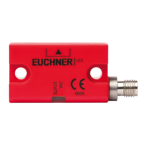
Operating Instructions
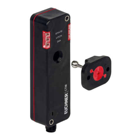
Transponder-Coded Safety Switch CTM-LBI-BP/BR-..D
2(translation of the original operating instructions) MAN20001661-01-05/23
Contents
1. About this document............................................................................................. 4
1.1. Scope............................................................................................................................................4
1.2. Target group ..................................................................................................................................4
1.3. Key to symbols...............................................................................................................................4
1.4. Supplementary documents ..............................................................................................................4
2. Correct use .......................................................................................................... 5
3. Description of the safety function .......................................................................... 6
4. Exclusion of liability and warranty ......................................................................... 7
5. General safety precautions ................................................................................... 7
6. Function............................................................................................................... 8
6.1. Bistable guard locking.....................................................................................................................8
6.2. Guard lock monitoring.....................................................................................................................8
6.3. Monitoring outputs/status bits .........................................................................................................8
6.3.1. Door position signal OD....................................................................................................8
6.3.2. Diagnostic signal OI .........................................................................................................8
6.3.3. Guard locking signal OL ...................................................................................................9
6.3.4. Status signal OM..............................................................................................................9
6.3.5. Locking element signal OLS..............................................................................................9
6.3.6. Communication connection C............................................................................................9
6.4. Guard locking .................................................................................................................................9
6.5. Switching states ...........................................................................................................................10
7. Manual release................................................................................................... 11
7.1. Auxiliary release............................................................................................................................11
8. Mounting............................................................................................................ 12
9. Electrical connection .......................................................................................... 13
9.1. Notes about .........................................................................................................................14
9.2. Safety in case of faults..................................................................................................................14
9.3. Fuse protection for power supply...................................................................................................14
9.4. Requirements for connecting cables...............................................................................................15
9.5. Connector assignments.................................................................................................................15
9.5.1. Connector assignment of safety switch CTM-…-BR-…-AZD-SA-…
with plug connector M12, 8-pin .......................................................................................15
9.6. Notes on operation with safe control systems.................................................................................15
10. Connection of a single CTM-BP/BR (separate operation)...................................... 16
11. Connection of several devices in a chain (series connection)................................ 17
11.1. Series connection with wiring in the control cabinet.........................................................................17
11.2. Series connection with Y-distributors ..............................................................................................18
11.2.1. Maximum cable lengths with BR switch chains..................................................................18
11.2.2. Determining cable lengths ..............................................................................................18
11.2.3. Connector assignment of Y-distributor for series connection with IO-Link communication .....19
