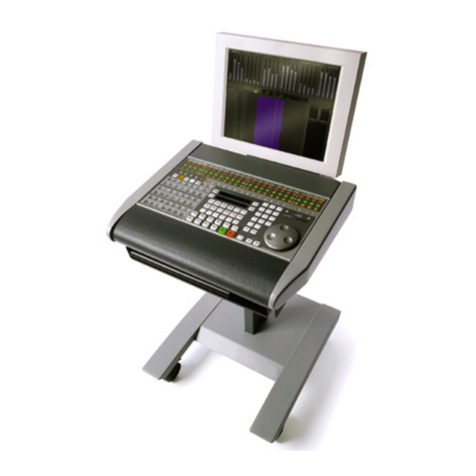
S5 Control Surface/Frame Manual Page 2 Version 1.0 ©1999 Euphonix, Inc.
TABLE OF CONTENTS
Box Inventory ............................................................................................................. 4
Safety and Precautions.............................................................................................. 4
Power On Sequence ............................................................................................................................ 5
CE/TUV/UL/CSA.......................................................................................................... 5
Component Overview ................................................................................................ 6
Functional Description ........................................................................................................................ 6
FRAME SECTION ......................................................................................7
Physical Specifications ....................................................................................................................... 7
Exploded View...................................................................................................................................... 7
Side Panel View.................................................................................................................................... 8
Dimensions and Weight ...................................................................................................................... 9
User Reference - Frame........................................................................................... 10
Assembling the S5 Frame................................................................................................................. 10
System 5 Ethernet/Power Cable Configuration .............................................................................. 18
System 5 Ethernet Cable Harness ................................................................................................... 19
CONTROL MODULES SECTION ............................................................21
Physical Specifications ........................................................................................... 21
Top View - Control Modules ............................................................................................................. 21
Filler Modules..................................................................................................................................... 22
Dimensions and Weight .................................................................................................................... 23
Technical Specifications ......................................................................................... 23
Environmental Requirements........................................................................................................... 23
Power Requirements ......................................................................................................................... 23
Power Consumption .......................................................................................................................... 23
Control Module Expansion Port ....................................................................................................... 24
General Description ....................................................................................................................... 24
Physical Pinout............................................................................................................................... 24
DB25 Electrical Specification: ........................................................................................................ 26
Typical Usage: ............................................................................................................................... 26
Alternate Usage #1: ....................................................................................................................... 27
Alternate Usage #2: ....................................................................................................................... 28
User Reference – Control Modules......................................................................... 29
Control Module Setup ....................................................................................................................... 29
Overview of Ethernet IP Address Allocation .................................................................................. 29
Self Test Procedure for CM401, CM402 and CM408....................................................................... 30
Initiating Self Test........................................................................................................................... 31
Self Test Operations ...................................................................................................................... 32
Top Level Test Keys ...................................................................................................................... 33
LED test ......................................................................................................................................... 34
All Switch LEDs Toggle.................................................................................................................. 35
Color Toggle................................................................................................................................... 35
All Switch and Indicator LEDs Toggle............................................................................................ 35
Vegas Mode ................................................................................................................................... 35
