EURA ELH-60B9 SILVER User manual

Door hanDle SeT
WITh aCCeSS ConTrol
Instruction manual
elh-70B9
BraSS
elh-80B9
BraSS
elh-60B9
BraSS
elh-70B9
SIlVer
elh-80B9
SIlVer
elh-60B9
SIlVer


INDEX
1. GENERAL CHARACTERISTICS AND INTENDED USE.........................................................................5
2. AVAILABLE DooR HANDLE SET VERSIoNS......................................................................................5
3. SET CoNTENTS: ....................................................................................................................................5
4. PRINCIPLE oF oPERATIoN................................................................................................................ 6
5. INSTALLATIoN oF LoCK IN DooR..................................................................................................... 6
5.2. INSTALLATIoN IN DooR WITHoUToPENINGS ........................................................................7
5.3. SETTING HANDLE oRIENTATIoN (LEFT-/RIGHT-HAND DooR) ............................................ 8
5.3.1. HANDLE oRIENTATIoN SETTING - FRoNT oFTHE DooR HANDLE SET.................... 8
5.3.2. HANDLE oRIENTATIoN SETTING – BACK oFTHE DooR HANDLE SET ..................... 8
5.4. EMERGENCY ENTRANCE............................................................................................................. 9
5.5. SETTING AND INSTALLATIoN oF THEARBoR IN THE DooR HANDLE SET ....................... 10
5.6. ELECTRIC CoNNECTIoNS .......................................................................................................... 10
6. PRoGRAMMING AND oPERATING ELH-60B9/ELH-70B9 DooR HANDLE SETS ..................... 11
6.1. PRoXIMITY CARD PRoGRAMMING (RFID) ............................................................................. 11
6.2. ACCESS CoDE PRoGRAMMING................................................................................................12
6.3. DELETING CARDS AND CoDES .................................................................................................12
7. PRoGRAMMING AND oPERATING ELH-80B9 DooR HANDLE SET............................................13
7.1. ACCoUNT REGISTRATIoN IN TTLoCK MoBILE APP ...............................................................13
7.2. LoGGING IN To THE TTLoCK APP.............................................................................................13
7.3. ADDING ELH-80B9 DooR HANDLE SETSWITH ACCESS CoNTRoL....................................13
7.4. oPERATING THE DEVICE...........................................................................................................14
8. TECHNICAL SPECIFICATIoN* ............................................................................................................16
WARRANTY ............................................................................................................................................19

PRELIMINARY COMMENTS
Please read this instruction manual carefully prior to installation, connection and use of the
device. In case of any issues with understanding of its contents please contact the device
vendor.
Self-installation and start up of the device is possible under the condition of using appro-
priate tools. However, it is recommended that installation of the device is performed by a
qualied personnel.
The manufacturer bears no liability for damage that can result from improper installation
and use of the device and performance of independent repairs and modications.

5
1. GENERAL CHARACTERISTICS AND INTENDED USE
Access control door handle sets enable simple restriction of access to unauthorized persons
to protected areas. They are intended for both le- and right-hand door wings, and the
versatile spacing of xing screws of 38~40.5 mm in the majority of cases enables use of a
lock that has already been installed in the door.
Depending on the model, the body of the door handle set includes:
-ELH-60B9 – proximity card reader (Unique 125 kHz);
-ELH-70B9 – proximity card reader (Unique 125 kHz) and physical numerical keypad;
-ELH-80B9 – proximity card reader (Mifare 13,56 MHz), numerical touchpad with Blue-
tooth module, application controlled
Upon card approximation, correct PIN code entering or mobile app use, the lock is released.
Door handle sets are intended for indoor installation and are available in two colour variants
– silver and antique brass.
2. AVAILABLE DOOR HANDLE SET VERSIONS
Fig. 1. ELH-60B9 brass/ silver door
handle set with RFID card reader Fig. 2. ELH-70B9 brass/ silver door
handle set with RFID card reader
and code keypad
Fig. 3. ELH-80B9 brass/silver door
handle set with touchpad, Blueto-
oth module and Mifare card reader
3. SET CONTENTS:
-external door handle set with door handle, electronic access control module and built-in
cylinder,
-internal door handle set with door handle, battery container and programming module,
- 2 keys for manual opening of the door in case of a failure,
- 3 non-programmed proximity cards*,
- 2 non-programmed proximity pendants*,
-installation elements,
-installation, programming and use guide.
* Elements not included in the ELH-80B9 set

6
4. PRINCIPLE OF OPERATION
Following an impulse from the electronic access control module, the servomotor unlocks
mechanical transmission, thus enabling door opening via normal pressing of the door han-
dle on the external door handle set. Opening is signalled via sound and LED being switched
on. The waiting time for handle pressing is set by the factory for a period of approximately 5
seconds, then the transmission is locked again and the lock awaiting another impulse from
the electronic access control module.
It is always possible to open the door via normal pressing of the door handle from the inter-
nal side (of the room). Aer the door is closed, the pawl mechanism activates immediately,
disabling opening of the door from the outside without the impulse from the electronic ac-
cess control module.
There is a possibility for emergency lock opening using a normal mechanical key, 2 pieces of
which are provided with each door handle set with access control (item 5.4).
5. INSTALLATION OF LOCK IN DOOR
The ELH-60B9/ ELH-70B9/ ELH-80B9 sets include an arbor enabling installation of door
handle sets in doors with 30~50 mm thickness.
Warning!
In the case of using ELW-06B9 spacers in doors with thickness in excess of 40 mm one
should remember to replace the arbor with a longer unit (approx. 70~80 mm*).
The spacer has identical openings as the one to be performed in the door wing.
In order to increase security, it is recommended that ELH-60B9/ ELH-70B9/ ELH-80B9
control door handle sets are installed in rebated doors.
Warning!
Installation shall be performed with emergency keys at hand, as they might prove indi-
spensable in the case of doors with non-programmed lock being slammed shut.
* Additional arbor not included.

7
Fig. 4.
5.1. INSTALLATION IN DOOR WITH OPENINGS
In order to install the ELH-60B9/ ELH-70B9 / ELH-80B9 door handle sets, rst check
whether the door possesses
a. suitable lock (Fig. 4 and installation openings for screws/ bushings with 38~41 mm spac-
ing (Fig. 4, Item 1)
b. cut out below the lock arbor (Fig. 4, Item 2) for the wire connecting electronics of the door
handle set with the power supply.
c. opening for the arbor socket with 25 mm diameter (Fig. 4, Item 3).
If suitable openings have been made in the door, the door handle set can be installed im-
mediately (move to item 5.3 of this guide).
5.2. INSTALLATION IN DOOR WITHOUT OPENINGS
If the door possesses no installation openings, the lock shall be removed from the door,
make sure that it complies with the standard provided in Fig. 4, and then four openings shall
be drilled:
a. two with diameter approx. 12 mm intended for connection of the internal and external
part of the door handle set (Fig. 4, Item 1).
b. one with 12 mm diameter to conduct the wire connecting the electronics with the power
supply (Fig. 4, Item 2)
c. one with 25 mm diameter intended for masking the arbor socket with locking pin (Fig. 4,
Item 3).

8
Note
1. Template (to be cut out) with the spacing of installation openings in 1:1 scale is provided
on page 13 of this guide.
2. In the case of using ELB-06B9 washers (bezels) performance of the 25 mm opening can
be omitted (Fig. 4, Item 3).
5.3. SETTING HANDLE ORIENTATION (LEFT-/RIGHT-HAND DOOR)
Subsequently, check the manner of door opening, to set the door handle set handle in a
proper manner. All door handle sets are universal and they can be installed on both le- and
right-hand doors.
5.3.1. HANDLE ORIENTATION SETTING - FRONT OF THE DOOR
HANDLE SET
In order to determine the direction of opening, just unscrew the xing screws located under the
opening plug (Fig. 5, Item 1), next to the cylinder of the door handle set lock (Fig. 5, Item 3). Then
remove the handle and rotate and install again using the screw (Fig. 5, Item 2).
Fig. 5.
5.3.2. HANDLE ORIENTATION SETTING – BACK OFTHE DOOR
HANDLE SET
In order to determine the direction of handle opening, unscrew the xing screw located
on the internal portion of the door handle set (Fig. 6, Item 1), then change its position and
install the handle again using the xing screw.

9
Fig. 6.
5.4. EMERGENCY ENTRANCE
Fig. 7.
In the case of a necessity to enter the room, the following shall be done using the emer-
gency key:
- remove the hole plug (Fig. 7, Item 1),
- insert the emergency key in the patent lock (Fig. 7, Item 2),
- by turning the key 90 degrees to the right unlock the door handle set mechanism,
- by pressing down the handle enter the room.
10
5.5. SETTING AND INSTALLATION OF THE ARBOR IN THE DOOR
HANDLE SET
The arbor shall be placed in the socket located in the device body marked with triangle (Fig.
9, Item 10), and the install the locking pin located in the accessory set.
Warning!
By installing the pin in the arbor remember that the element
located on the lock body is directed towards the handle (Fig. 9,
Item 10 and item 5.3).
Having placed the pin adjust it so that it ts the prepared ope-
ning of the arbor socket.
Fig. 8.
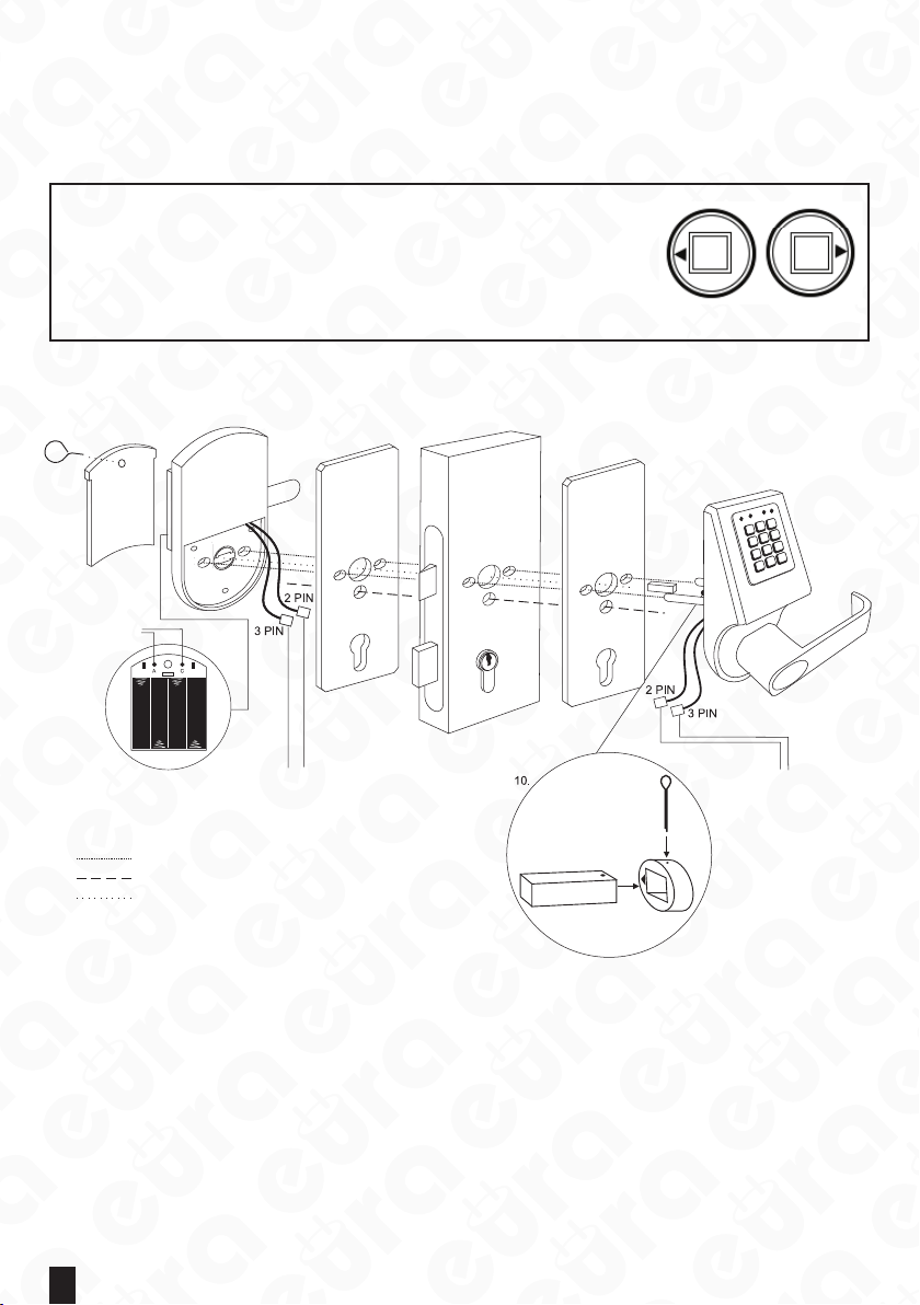
5.6. ELECTRIC CONNECTIONS
1. Battery chamber
cover
7. Coding
buttons
8. Battery chamber 9. Connecting wires
Route for bushings and screws connecting both lever set sides
Route for the wire connecting the electronics with the power supply
Route for the arbor connecting the external and internal portion of
the handle
9. Connecting wires
2. Lever set back 3. ELW-06B9 masking
washer (optional)
4. Lock in door wing
5. ELW-06B9 masking
washer (optional)
6. Lever set front
Arbor
Fig. 9.
The electromechanical lock door handle set is supplied by DC 6 V power (4 x alkaline battery
type AA 1.5 V).
To install the lock door handle set in door:
-use the existing one or prepare installation holes in accordance with the template pro-
vided on page 13 of this guide,
-screw the installation bushings into the screw union of the internal part of the door han-
dle set,
-insert connection wires from the external portion of the door handle set into the opening
made under the arbor opening,
- put the external portion of the door handle set with connecting bushings through the
door wing with the lock installed,

11
- place the internal portion of the door handle set and screw the xing screws into the
openings located next to the handle, into the bushings in the external portion,
-remove the cover of the battery chamber (Fig. 9, Item 1) using a special key included in the
set or other sharp tool
- place 4 alkaline 1.5 V batteries type AA into the power supply chamber,
- code the lock (see item 7)
-close the battery chamber.
Warning!
It is recommended that installation and programming ofthe door handle set is performed
with the door wing open, upon check of the operation the door can be closed.
Aer the rst insert of batteries, the door handle set automatically enters the set status,
thus it should be remembered to insert batteries only aer the door handle set is instal-
led in the door wing. If the batteries have been inserted earlier, to open the door use the
emergency key, which is recommended to be at hand during installation.
6. PROGRAMMING AND OPERATING ELH-60B9/ELH-70B9 DOOR
HANDLE SETS
The battery chamber is located on the external portion of the door handle set (installed
from the side of the room). Prior to the rst start up and programming of the lock, place 4
working 1.5V batteries type AA in the battery chamber and connect all plugs in accordance
with the chart shown in Fig. 9, Item 9.
Warning!
For the door handle set to operate properly, it is recommended to use alkaline batteries,
and not rechargeable batteries.
Aer the batteries are partially depleted, low power supply status will be signalled through
a red LED, yet approximately 100 lock opening cycles will still be possible to perform. The
lock programming is simple and secure. Programming buttons are located on the internal
side of the door handle set, that is from the room side. These are the buttons marked as ‘A’
and ‘C’ in Fig. 9, Item 7.
The lock models with numerical keypad (encoder) have the so called ‘transfer function’ ac-
tive, that is aer their installation, door can be opened using the default code ‘88888888’.
This function is active only until the rst programming of the target code.
6.1. PROXIMITY CARD PROGRAMMING (RFID)
Every set includes 3 non-programmed proximity cards and 2 pendants. Up to 100 user cards
can be programmed per one lock. Card programming is done as follows:
-remove the cover of the battery chamber (Fig. 9, Item 1) using a special key included in the
set or other sharp tool,
- single pressing of the ‘A’ button (Fig. 9, Item 7), will result in activation of the coding mode,
which will be signalled by blue LED,
- approximate the programmed RFID cart within 6 seconds, the speaker will generate a
brief sound, the blue LED will be ashing,
- in order to program a larger number of RFID cards, approximate subsequent cards at in-
tervals shorter than 6 seconds (when the blue LED is ashing)

12
6.2. ACCESS CODE PROGRAMMING
ELH-70B9 door handle set models, apart from the card reader are equipped with numerical
keypad, enabling access to the protected zone using a digital code (PIN). Aer the entire lock is
assembled and connected to power supply, the access cards can be programmed to cooperate
with the lock (in the manner described in the chapter no. 8.1). A possibility exists to program up
to 25 various digital access codes with the length from 6-10 digits. Each code at the moment
of programming as well as lock release shall be nished with the ‘#’ button. PIN code program-
ming is done as follows:
- remove the battery chamber cover (Fig. 9, Item 1) using a special key included in the set or
other sharp tool,
- single pressing of the ‘A’ button (Fig. 9, Item 7), will result in activation of the coding mode,
which will be signalled by green LED,
- enter a new access code within 6 seconds, nish the code with the ‘#’ button, speaker gener-
ates a brief sound, green LED will be ashing,
- repeat the access code enter to conrm the operation, nish by pressing the ‘#’ button, a
longer sound in the speaker will mean successful code programming.
When programming RFID cards and digital codes atthe same time, a possibilityfor an alterna-
tive access to the room will exist – using a code or a card.
ELH-70B9 door handle sets possess an active lock function. Aer 3 erroneous attempts to en-
ter an incorrect access code, the set is automatically locked for the period of approx. 3 minutes.
This status can be determined by the absence of sound reaction to pressing the ‘#’ button.
Warning!
The access code programmed by factory is ‘88888888’. Upon programming of a new ac-
cess code by the user, the factory access code becomes invalid.
6.3. DELETING CARDS AND CODES
In order to delete RFID cards or access codes from the system in any version of the lock, the
lock initialization function shall be started, which deletes all previously entered settings. Lock
initialization function is performed as follows:
-remove the cover of the battery chamber (Fig. 9, Item 1) using a special key included in the
set or other sharp tool,
- press and hold the ‘C’ button for about 6 seconds (Fig. 9, Item 7), aer that the speaker gen-
erates a brief sound, and the red LED switches on, and the second sound signal appears in
the speaker,
- aer the rst signal, release the ‘C’ button, the red and green or blue LEDs (depending on
model) will be ashing interchangeably, longer sound in the speaker will mean successful
initialization of lock settings.
Warning!
It is not possible to remove a single card or code.

13
7. PROGRAMMING AND OPERATING ELH-80B9 Door handle SET
Prior to the rst start up and programming, place 4 working 1.5 V batteries type AA in the
battery chamber and connect all plugs in accordance with the chart shown in Fig. 9.
Note: Forthe door handle setto operate properly, it is recommended to use alkaline batter-
ies, and not rechargeable batteries.
The battery status will be visible in mobile application aer synchronization of the app with
the door handle set.
In order to program the ELH-80B9 Door handle set with access control, download the
TTLock app from GooglePlay for Android devices or from AppStore for iOS devices, and then
follow the below instruction.
7.1. ACCOUNT REGISTRATION IN TTLOCK MOBILE APP
7.1.1. in the upper right corner click ‘Register’;
7.1.2. select registration mode by phone/e-mail;
7.1.3. enter the phone number/e-mail address;
7.1.4. set the password;
7.1.5. select the verication code by clicking ‘Get code’:
7.1.6. enter the code provided via text message/e-mail;
7.1.7. provide answers to security questions in the case of the password being lost - an-
swer 3 questions selected from the list of suggestions.
7.2. LOGGING IN TO THE TTLOCK APP
Aer the account is created, log in to the app by entering your phone number/e-mail ad-
dress and the set password.
7.3. ADDING ELH-80B9 DOOR HANDLE SETS WITH ACCESS CON-
TROL
First adding
In the case of adding the rst device, click in the round eld of the start screen with inscription
‘+Add lock’, and then move to the activities described from item 7.3.3
Adding further devices
7.3.1. Click the icon with ‘user” in the le upper corner of the app, which is followed by
the app’s main menu appearing;
7.3.2. from the main menu select rst position ‘+Add locks’;
7.3.3. if Bluetooth is not switched on, the app will ask for initiating, agree to add a lock;
7.3.4. from the selection menu of device types, select the rst position ‘Door Lock’;
7.3.5. in order to introduce electronics into pairing state, hold the door handle set key-
pad until the illumination appears;
7.3.6. Aer searching is nished, the app will show the list of found devices.
7.3.7. select the added device from the list. Note: in order to pass through the pairing
process easily, add devices one by one and check if the device’s keypad is illumi-
nated;
7.3.8. having selected the device, the app will move automatically to the main menu of
door handle set management.
7.3.9. then, select option Setting(see item 7.4.8) and then Clock, which opens the LOCK
CLOCK page, where the time shall be synchronized by clicking Adjust Clock

14
7.4. OPERATING THE DEVICE
7.4.1. The lock icon in the upper portion of the app screen enables releasing the lock
that remains in the range of the Bluetooth transmitter in the device with the
app installed.
7.4.2. „Send eKey” - eKeys are access keys, which can be send to other app users,
typically dedicated to the personnel operating the protected room. These keys
enable opening lock that remains within the range of Bluetooth transmitter, in
order to send the eKey:
7.4.2.1. select the eKey icon;
7.4.2.2. select the key type by clicking ‘Type’ - you can choose between:
- timed
- permanent
- one-time;
7.4.2.3. in the ‘Account’ eld enter the account name of the user, who is
provided with the key;
7.4.2.4. in the ‘Name’ eld enter the key name;
7.4.2.5. in the case of a timed key, specify its period of validity
7.4.2.6. send the key by clicking ‘Send’.
In order to open door using an eKey, click the lock icon in the app.
7.4.3. „Send Passcode” - these are access codes sent to door handle set users
(guests, employees, visitors), in order to send an access code, click ‘Send Pass-
code’ icon, and:
7.4.3.1. select the code type:
- permanent - the code must be used at least once within 24 h from
being established, otherwise it loses validity;
- timed - the code must be used at least once within 24 h from being
established, otherwise it loses validity;
- one-time - single-use code - the code must be used at least once
within 6 h from being established, otherwise it loses validity;
- erase - erasing code, should be used within 24h, otherwise it expires.
Aer its application all codes assigned to the given device are erased.
In order for the code list in the app to be cleared, perform app and
door handle set synchronization, this is best done using door open-
ing via the lock icon;
- customized - manual code - enables full personalization of code
thanks to the possibility to select the operation time and the code
number (4-9 signs);
Note: option available only in the case when the mobile device re-
mains within the operating range of the door handle set’s Bluetooth
module;
- cyclic - cyclic code enables setting access according to the scheme,
it is possible to select the day of the week and hours for the code to
work - the code must be used at least once within 24 h since being
established, otherwise it loses expires.
7.4.3.2. generate code by clicking ‘Generate’
7.4.3.3. click the icon of square with arrow in the upper right corner of the app.

15
7.4.3.4. From the list, select the code transmission method:
- WeChat - the code will be sent via WeChat app, under the condition the
WeChat app is congured;
- Text Meg - the code will be sent via a text message- the text message
will contain a template with information on the access code, its expiry
date etc. - it is possible to edit any text messages;
- E-mail - the message will be sent via e-mail, under the condition of pos-
sessing congured e-mail account on the mobile device.
7.4.4. eKeys - list of generated and sent access codes - with information on keys - key
type, activity status - it is possible to remove the given keyfrom the list, in orderto
remove press and hold the given key until ‘Delete’ button appears, upon its click-
ing the key becomes permanently deleted.
NOTE: Removing an active key from the list in the app prior to its expiration is
possible, in orderto remove, the device with the app must be connected to the In-
ternet, and the key will be removed only when the person receiving the key is also
connected to the Internet. Information on premature key removal will be down-
loaded from server.
All keys can be deleted from the list at once:
- click the icon with three dots in the upper right corner of the app;
- select reset eKeys;
- conrm that you want to reset keys - enter the password of the app administrator.
7.4.5. Passcodes - list of generated and sent access codes -with information on codes -
type, activity status - it is possible to remove the given code from the list, in order
to remove press and hold the given code until ‘Delete’ button appears, upon its
clicking the key becomes permanently deleted.
NOTE: In order to remove a permanent code, one must remain within the range of
the Bluetooth transmitter built in the door handle set.
All codes can be deleted from the list at once:
- click the icon with three dots in the upper right corner of the app;
- select reset passcodes;
- conrm that you want to reset codes - enter the password of the app administrator.
7.4.6. 1C Cards - door handle sets with access control possess Mifare 13.56 MHz card
reader built in. By clicking the IC Cards icon, the card management panel is opened.
In order to add the Mifare card:
- click the icon with three dots in the upper right corner;
- select ‘add IC Cards’ option;
- enter the card name in the ‘Name’ eld;
- select the access type - permanent or timed;
- in the case of a timed access being selected, specify its period of validity;
- click OK and wait for signal from the door handle set;
- aer the sound message, place card near the ‘2’ digit in the numerical keypad of
the device;
All cards can be deleted from the list at once:
- click the icon with three dots in the upper right corner of the app;
- select ‘Clear IC cards’;
- conrm that you want to reset cards - enter the password of the app administrator.

16
7.4.7. Records - device logbook.
7.4.8. Settings – clicking the Settings icon provides us with information on the device:
- lock id - lock no.;
- MAC - MAC adress;
- Battery - battery status;
- Validity - access validity;
- Lock name - here you can enter the lock name, e.g. Room 308;
- Group - lock group- here you can create a group, to which door handle sets can
be assigned, e.g. Floor 1;
- Admin passcode - administrator code;
Lock clock - option for synchronization of app and door handle set clocks;
Fault Diagnosis - diagnosis of issues with the lock;
Lock upgrade - soware update;
Attendance - attendance;
Unlocking alert - information on the door handle set being unlocked.
Warning!
Following each battery exchange it is necessary to perform synchronization of the door
handle set’s clock with the app’s clock, if synchronization is not performed the codes may
not work correctly.
8. TECHNICAL SPECIFICATION*
ParaMeTr elh-60B9
SIlVer/ BraSS elh-70B9
SIlVer/ BraSS elh-80B9
SIlVer/ BraSS
Power supply voltage 6 V DC
Power supply type Alkaline batteries (4 x AA 1.5V) or power supply unit.
Energy consumption - standby / operation 12 µA / 6.4 mA 16 µA / 72 mA <18uA / 95 mA
Max. no. of users 100 cards 100 cards + 25 codes no limit
Permissible relative humidity <80%
Intended for le-/right-winged doors
Case material Zinc alloy
Time of release impulse Approx. 5 sec.
Recommended installation site indoors
Proximity reader Unique 125 kHz Unique 125 kHz Mifare 13.56 MHz
Encoder No Mechanical Touch
Fingerprint reader No
Bluetooth No No Yes
Bluetooth transmitter power output 4dB
Temperature operating range -10°C ~ +70°C
Protection coecient IP20
Dimensions of the external door handle set (H xW x T) 154 x 74 x 77 mm
Dimensions of the internal door handle set (H xW x T) 152 x 76 x 70 mm
Net weight 1660 g
*the manufacturer reserves the right to make changes to the technical parameters without prior notice.


18

19
WARRANTY
As the only distributor of the Eura products, Eura-Tech is obliged to ensure ecient war-
ranty and post-warranty service. In the countries where Eura-Tech has neither its own
service network, nor DOOR-TO-DOOR service, the quality claims are dealt with by autho-
rised distributors of the Eura products on the basis of the signed distribution agreements.
Within the framework of such agreements, Eura-Tech will ensure nancing of the possible
repairs and delivery of spare parts.

EURA-TECH Sp. z o.o.
ul. Przemysłowa 35A, 84-200 Wejherowo, Poland
www.eura-tech.eu
All rights reserved.
The pictures, drawings and texts used in this manual are the property of ‘EURA-TECH’ Sp. z o.o. Reproduction, distribution and publication
of the whole or parts ofthe manual without the author's consent are prohibited!
The Eura-Tech Sp. z o.o. company reserves the right to change technical parameters and modify the operating instructions without notication.
At the same time, we would like to inform thatthe most up-to-date version of the manual can be found onthe website www.eura-tech.eu
on the subpage ofthe given product.
The EU declaration of conformity of the given device is provided on the http://www.eura-tech.eu website
2018/04
Eura-Tech Sp. z o.o. hereby declares that the radio equipment type - ELH-80B9 access control
door handle set - is in accordance with Directive 2014/53/EU.
Full text of the EU declaration of conformity is available under the following web address:
www.eura-tech.eu
This manual suits for next models
5
Table of contents
Other EURA Door Lock manuals


Popular Door Lock manuals by other brands


Dormakaba
Dormakaba Grange user guide

Schlage
Schlage ND40 How to Install Button in Field

Assa Abloy
Assa Abloy Sargent AL-PE80 Series installation instructions

BANKSTON
BANKSTON Edition Office Pull 01 installation instructions

E-LOK
E-LOK 7 Series user manual

ANXELL
ANXELL AXM-800M Series Installation instruction