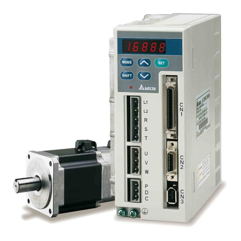
EURA SD20-G Series User manual

About this manual
■ Description of technical terms
The terms in this manual are defined as follows:
Servodrive is used to drive and control servo motor.
Servo System means a servo control system that includes the combination of a servodrive, servo motor with a host
computer and peripheral devices.
Parameters include monitoring parameter and setting parameters. Monitoring parameters can only be checked,
but not be modified, and setting parameters can be checked and modified, which includes function parameters and
data parameters.
■ Common symbol
The following symbols are used for convenience.
1. Instruction
P: position mode
Pt:position pulse mode
ALL: all modes
Pr:internal register position mode
S: speed mode
Sr:internal register speed mode
Sz:analog speed mode
T: torque mode
Tr:internal register torque mode
Tz:analog torque mode
2. Usage of backslash (/)
Backslash is used in the wiring diagram. It describes the default logic of I/O interface.
For input signal (DI terminal), balckslash means, when input circuit is ON status, the input signal is valid, i.e. the
default logic is positive logic. Without blackslash means, when input side is OFF status, the input signal is valid,
i.e. the default logic is negative logic.
For output signal (DO terminal), backslash means output side circuit is common-opened, and when the signal is
output, the output side circuit is closed. Without backslash means output side circuit is common-closed, and when
the signal is output, the output side circuit is opened.
3. Others
NC: no connection
N/A: no unit

SD20-G Series
2
I NOTES FOR SAFE OPERATION..............................................................................................8
II MODEL SELECTION................................................................................................................. 11
2.1 SERVO DRIVE INTRODUCTION.................................................................................................... 11
2.1.1 SERVO DRIVE NAMEPLATE..................................................................................................... 11
2.1.2 CONNECTION TO PERIPHERAL DEVICES .................................................................................12
2.1.3 SERVO DRIVE SPECIFICATION..................................................................................................13
2.1.4 CONNECTION TO PERIPHERAL DEVICES .................................................................................16
2.2 SERVO MOTOR...........................................................................................................................17
2.2.1 SERVO MOTOR NAMEPLATE AND MODEL.................................................................................17
2.2.2 SERVO MOTOR COMPONENT ...................................................................................................18
2.2.3 SERVO MOTOR MODEL............................................................................................................19
2.3 COMBINATION OF SERVOMOTORAND SERVODRIVE....................................................................22
2.4 INPUT FILTER MODELAND DIMENSIONS .....................................................................................25
III INSTALLATION........................................................................................................................32
3.1 SERVO DRIVES INSTALLATION....................................................................................................32
3.1.1 INSTALLATION CONDITIONS....................................................................................................32
3.1.2 INSTALLATION PROCEDURE AND MINIMUM CLEARANCES .......................................................33
3.1.3 SERVO DRIVE DIMENSION.......................................................................................................34
3.2 SERVO MOTOR INSTALLATION....................................................................................................39
3.2.1 INSTALLATION LOCATION .......................................................................................................39
3.2.2 INSTALLATION CONDITIONS .................................................................................................39
3.2.3 PRECAUTIONS ON SERVO MOTOR INSTALLATION.....................................................................42
3.2.4 SERVO MOTOR DIMENSION .....................................................................................................43
IV WIRING ......................................................................................................................................47
4.1 MAIN CIRCUIT WIRING...............................................................................................................49
4.1.1 MAIN CIRCUIT TERMINALS .....................................................................................................49
4.1.2 MAIN CIRCUIT TERMINAL WIRING ..........................................................................................52
4.1.3 TYPICAL MAIN CIRCUIT WIRING EXAMPLES ............................................................................55
4.1.4 PRECAUTION FOR MAIN CIRCUIT WIRING................................................................................57
4.2 ENCODER WIRING......................................................................................................................58
4.2.1ABSOLUTE ENCODER CONNECTOR TERMINAL LAYOUT ...........................................................58
4.2.2 RESOLVER ENCODER CONNECTOR TERMINAL LAYOUT............................................................59

SD20-G Series
3
4.2.3 INCREMENTAL ENCODER CONNECTOR TERMINAL LAYOUT......................................................58
4.3 I/O SIGNAL WIRING .................................................................................................................59
4.3.1 POSITION COMMAND INPUT SIGNALAND FUNCTION ...............................................................63
4.3.2ANALOG COMMAND INPUT SIGNALAND FUNCTIONS...............................................................68
4.3.3ANALOG OUTPUT SIGNALAND FUNCTIONS .............................................................................68
4.3.4 DIGITAL INPUT SIGNALAND FUNCTIONS .................................................................................69
4.3.5 ENCODER FREQUENCY-DIVISION OUTPUT SIGNALAND FUNCTION ..........................................72
4.3.6 COMMUNICATION WIRING ......................................................................................................74
4.3.7 WIRING WHEN USING MORE THAN ONE SERVOS......................................................................75
4.3.8ABSOLUTE VALUE ENCODER...................................................................................................77
4.4 SERVO DRIVE AND SERVO MOTOR WIRING .................................................................................79
4.4.1 ENCODER WIRING...................................................................................................................79
4.4.2 POWER CABLE OF SERVO DRIVE AND SERVO MOTOR...............................................................82
4.5 EMC.........................................................................................................................................83
4.5.1 DEFINITION ............................................................................................................................83
4.5.2 INSTALLATION ENVIORNMENT ...............................................................................................83
4.5.3 SELECTION AND INSTALLATION OF PERIPHERAL EMC DEVICES.............................................84
4.5.4 SHIELDED CABLE .................................................................................................................84
V. OPERATION AND PARAMETERS......................................................................................86
5.1 KEYPAD DESCRIPTION ...............................................................................................................86
5.2 KEYPAD OPERATING PROCEDURE ..............................................................................................87
5.2.2 PARAMETERS INSTRUCTIONS..................................................................................................88
5.3 KEYPAD OPERATING PROCEDURE...............................................................................................90
5.3.1 EXAMPLE OF MONITOR FUNCTION PARAMETER ......................................................................90
5.3.2 EXAMPLE OF AUXILIARY PARAMETERS USAGE........................................................................91
5.3.3 PARAMETER SETTING .............................................................................................................92
VI.RUN……………………………………………………………………………………………....92
6.1 BASIC PARAMETERS SETTING ....................................................................................................97
6.1.1 BEFORE RUNNING...................................................................................................................97
6.1.2 POWER ON ...........................................................................................................................97
6.1.3 PARAMETERS SETTING..........................................................................................................100
6.1.4 SETTING THE OVERTRAVEL LIMIT FUNCTION.......................................................................105
6.1.5 JOG OPERATION PROCEDURE ................................................................................................107
6.1.6 TIMING SEQUENCE CONTROL................................................................................................108

SD20-G Series
4
6.1.7 SETTING THE BRAKING......................................................................................................... 110
6.2 SPEED MODE ........................................................................................................................... 114
6.2.1 PARAMETERS SETTING.......................................................................................................... 114
6.2.2 SOFT START ..........................................................................................................................122
6.2.3 SCURVE SMOOTHNESS FUNCTION......................................................................................123
6.2.4 ZERO CLAMP FUNCTION .....................................................................................................124
6.2.5 SPEED OUTPUT SIGNAL ......................................................................................................124
6.3 TORQUE MODE......................................................................................................................128
6.3.1 PARAMETERS SETTING .......................................................................................................128
6.3.2 SOFT START ..........................................................................................................................133
6.3.3 SPEED LIMITING AT TORQUE MODE.....................................................................................134
6.3.4 LIMITING TORQUE .............................................................................................................134
6.3.5 RELATED OUTPUT.................................................................................................................136
6.4 POSITION PULSE MODE ............................................................................................................136
6.4.1 PARAEMETERS SETTING........................................................................................................137
6.4.2 SETTING ELECTRONIC GEAR ................................................................................................. 154
6.4.3 POSITION COMMAND FILTER................................................................................................. 157
6.4.4 SOFT START OF POSITION COMMAND ....................................................................................157
6.4.5 POSITION COMMAND INHIBIT FUNCTION...............................................................................158
6.4.6 COMMAND PULSE CLEAR FUNCTION.....................................................................................158
6.4.7 FREQUENCY-DIVISION OUTPUT FUNCTION............................................................................159
6.4.8 HOMESEARCHMODE............................................................................................................163
6.4.9MECHANICAL ORIGIN SEARCH FUNCTION ............................................................................169
6.4.10 FIXED LENGTH INTERRUPT FUNCTION ...............................................................................171
6.4.11 DO OUTPUT RELATED TO POSITION PULSE ..........................................................................173
6.4.12 FULL CLOSED LOOP FUNCTION ...........................................................................................174
6.4.13 GANTRY SYCHRON FUNCTION ...........................................................................................177
6.4.14 ELECTRONIC CAM (E-CAM)FUNCTION..............................................................................181
6.5 DUAL MODE............................................................................................................................192
6.5.1 USER PARAMETER SETTING................................................................................................192
6.5.2 INTERNAL SPEED AND POSITION PULSE DUAL MODE ..........................................................193
6.5.3ANALOG SPEED AND POSITION PULSE DUAL MODE.............................................................194
6.5.4 ANALOG SPEED AND INTERNAL REGISTER POSITION DUAL MODE........................................195
6.5.5 INTERNAL SPEED AND INTERNAL REGISTER POSITION DUAL MODE......................................196
6.5.6 TOREQUE MODE AND POSITION PULSE DUAL MODE.......................................................... 197

SD20-G Series
5
6.5.7 TORQUE MODE AND INTERNAL REGISTER POSITION DUAL MODE .....................................198
6.5.8 POSITION PULSE AND INTERNAL REGISTER POSITION DUAL MODE....................................199
6.5.9 INTERNAL SPEED AND ANALOG SPEED DUAL MODE ..........................................................200
6.5.10 SPEED AND TORQUE DUAL MODE ......................................................................................200
6.5.11ANALOG TORQUE AND INTERNAL REGISTER TORQUE DUAL MODE ...................................200
6.6AUXILIARY FUNCTION.............................................................................................................201
6.6.1 SOFTWARE VERSION......................................................................................................201
6.6.2 SETTING PASSWORD......................................................................................................202
6.6.3SERVO DRIVE STATUS DISPLAY………………………………………………………202
6.6.4 CONTROLMODE OF FAN ...............................................................................................205
6.6.5 PARAMTER COPY............................................................................................................206
6.6.6 REVERTING TO MFR’SVALUE......................................................................................206
6.6.7 MOTOR PROTECTION FUNCTION…………………………………………………….206
6.6.8 TORQUE UNREACHED PROTECTION CONTROL.......................................................................208
6.6.9 DI TERMINALS FILTER FUNCTION......................................................................................208
6.6.10 OTHER OUTPUT SIGNALS ...................................................................................................210
6.6.11 FRICTION TORQUE COMPENSATION …………………………………………….…..….208
6.6.12 GRAVITY TORQUE COMPENSATION…………………………………………………………..209
6.6.13 INPUT POWER PHASE-LOSS PROTECTION…………………………………………………...210
6.6.14 ENCODER DISCONNECTION PROTECION…………………………………………………….210
6.6.15 OTHER OUTPUT SIGNALS……………………………………………………………………….210
6.7 HIGH-SPEED COUNTER FUNCTION ........................................................................................214
6.7.1 OVERVIEW..........................................................................................................................214
6.7.2 HIGH-SPEED COUNTING.......................................................................................................214
6.8 BUILT-IN PLC FUNCTION ........................................................................................................220
6.8.1 SUMMARY............................................................................................................................220
6.8.2 SERVO BUILT-IN PLC SOFTWARE ACCESS AREA...................................................................221
6.8.3 BUILT-IN PLC PROGRAM DESIGN.........................................................................................226
6.8.3.1 DATA MOVE INSTRUCTION................................................................................................226
6.8.3.2ARITHMETIC INSTRUCTION................................................................................................227
6.8.3.3 LOGIC INSTRUCTION .........................................................................................................235
6.8.3.4 PROGRAM CONTROL INSTRUCTION ...................................................................................239
6.8.4 BUILT-IN PLC PARAMETERS.................................................................................................244
6.8.5 BUILT-IN PC/PLC USE AND APPLICATION EXAMPLE............................................................247
6.8.6 BUILT-IN PLC COMMUNICATION OPERATION.......................................................................252

SD20-G Series
6
6.8.6.1 MODBUSADDRESS.........................................................................................................252
6.8.6.2 DEBUG FUNCTION OF BUILT-IN PLC............................................................................252
VII. ADJUSTMENTS ....................................................................................................................253
7.1 SUMMARY...............................................................................................................................253
7.2 INERTIAIDENTIFICATION.........................................................................................................254
7.2.1 OFFLINE INERTIAIDENTIFICATION........................................................................................254
7.2.2 ONLINE INERTIAIDENTIFICATION.........................................................................................256
7.3 GAIN ADJUSTMENT .................................................................................................................258
7.3.1 SUMMARY............................................................................................................................258
7.3.2AUTOMATIC GAIN ADJUSTMENT ..........................................................................................259
7.3.3 MANUAL GAIN ADJUSTMENT...............................................................................................261
7.3.4 GAIN SWITCH.......................................................................................................................263
7.4 VIBRATION INHIBITION............................................................................................................266
7.4.1 VIBRATION INHIBITION FUNCTION .......................................................................................266
7.4.2 LOW-FREQUENCY VIBRATION INHIBITION FUNCTION...........................................................267
VIII LIST OF PARAMETERS .....................................................................................................268
8.1 .1 MONITOR FUNCTION GROUP(LO-□□) ..........................................................................268
8.1.2 UTILITY FUNCTION GROUP (SO-□□) ..................................................................................271
8.1.3 MAIN FUNCTION GROUP (PO-□□□)..........................................................................279
8.1.4 MOTOR FUNCTION GROUP(HO-□□□)........................................................................310
8.1.5 ALARM RECORD PARAMETERS(HO2□□~HO3□□).................................................312
8.1.6 HIGH-SPEED COUNTER PARAMETERS(PL□□□)..............................................................315
ⅨMAINTENANCE AND INSPECTION....................................................................................330
9.1ALARM AND TROUBLE SHOOTING AT START.............................................................................330
9.1.1 POSITION CONTROL MODE....................................................................................................330
9.1.2 SPEED CONTROL MODE.........................................................................................................332
9.1.3 TORQUE CONTROL MODE......................................................................................................333
9.2ALARM CODE AND POSSIBLE CAUSE ........................................................................................334
9.3ALARM DISPLAY TABLE AND TROUBLE SHOOTING..................................................................335
9.3.1 OTHER MALFUNCTIONS........................................................................................................339
X COMMUNICATION .................................................................................................................340

SD20-G Series
7
10.1 COMMUNICATION..................................................................................................................340
10.1.1 MODBUS GENERAL..........................................................................................................340
10.1.2 MODBUS PROTOCOL........................................................................................................340
10.1.3 PARAMETER RELATED TO COMMUNICATION .......................................................................344
XIAPPENDIX................................................................................................................................346
11.1 ENCODER CABLE SELECTION .................................................................................................346
11.1.1ABSOLUTE ENCODER CABLE...............................................................................................346
11.1.2 INCREMENTAL ENCODER CABLE .........................................................................................347
11.1.3 RESOLVER ENCODER CABLE ...............................................................................................348
11.2 CONTROL CABLE ...................................................................................................................348
11.3 POWER CABLE.......................................................................................................................349
11.4 OTHER CABLE .......................................................................................................................350
11.5 MOTOR AND MATCHED CABLE ...............................................................................................350

SD20-G Series
8
I Notes for safe operation
Read this manual thoroughly before checking products on delivery, storage and transportation, installation, wiring,
operation and inspection, and disposal of the servo drives.
WARNING
·Do not touch terminals for five minutes after voltage resistance test.
·Do not touch terminals for five minutes after the power is turned off. Residual voltage may cause
electric shock.
·Never touch any rotating motor parts while the motor is running.
·Never touch the inside of the SERVOPACKs.
·Follow the procedures and instructions for trial operation precisely as described in this manual.
·Do not remove the front cover, cables, connectors, or optional items while the power is ON.
·Do not damaged, press, exert excessive force or place heavy objects on the cables.
·Do not change the max speed value (Po002) except special purpose. Failure to observe this warning
may result in damaged to products.
·Do not come close to the machine Immediate after resetting momentary power loss to avoid an
unexpected restart. Take appropriate measures to ensure safety against an unexpected restart.
·Do not modify products. Failure to observe this warning may result in injury or damage to products.
·MCtt (electromagnetic contactor) and NFB (no fuse breaker) must be installed between main circult
power (L1/R, L2/S, L3/T for 3-phase).

SD20-G Series
9
Storage and Transportation
CAUTION
·Do not store or install the product in the following places:
1. Locations subject to direct sunlight.
2. Locations subject to temperatures outside the range specified in the storage or installation
temperature conditions.
3. Locations subject to humidity outside the range specified in the storage or installation temperature
conditions.
4. Locations subject to corrosive or flammable gases.
5. Locations subject to dust, salts or iron dust.
6. Locations subject to exposure to water, oil, or chemicals.
7. Locations subject to shock or vibration.
·Do not hold the product by the cables or motor shaft while transporting it.
·Do not place any load exceeding the limit specified on the packing box.
Installation
CAUTION
·Never use the products in an environment subject to water, corrosive gases, inflammable gases, or
combustibles.
·Do not step on or place a heave object on the product.
·Do not cover the inlet or outlet ports and prevent any foreign objects from enternign the product.
·Be sure to install the product in the correct direction.
·Provide the specified clearances between the SERVOPACK and the control panel or with other
devices.
·Do not apply any strong impact.

SD20-G Series
10
Wiring
CAUTION
·Do not connect a three-phase power supply to the U, V, or W output terminals.
·Connect U, V and W of servo drive directly to U, V, and W of servo motor, avoid using contactor in
between.
·Securely connect the power supply terminals and motor output terminals.
·Do not connect servo drive for 220V directly to 400V voltage.
·Do not bundle or run power and signal lines together in the same duct. Keep power and signal lines
separated by at least 30 cm.
·Use twisted-pair shielded wires or mult-core twisted pair shielded wires for singal and encoder
cables.
·The maximum length is 3m for reference input lines and the maximum length is 20m for encoder
cables.
·Take appropriate and sufficient countermeasures for each form of potential interference when
installing systems in the following locations.
Locations subjects to static electricity or other forms of noise.
Locations subjects to strong electromagnetic fields and magnetic fields.
Locations subjects to possible exposure to radioactivity.
·Repair or maintain the servo drive only after the CHARGE indication on the servo drive goes off.
Maintenance and Inspection
CAUTION
·Repair or maintenance of the servo drive can be performed only by qualified personnel.
·Please cut off all connection between servo drive with resistor before performing an insulation test
of resistor.
·When replacing the servo drive, resume operation only after transferring the previous servo drive
parameters to the new servo drive or computer.
·Do not attempt to change wiring while the power is ON.
·Do not disassemble the servo motor.

SD20-G Series
11
II Model selection
2.1 Servo drive introduction
2.1.1 Servo Drive Nameplate
M2
Product series
- G 102 T3 M2
M4
M5 420
x
210 x
234
218
x
100 x
203
380
x
185 x
215
M6 270 x 234
498x
SD20
MM4 336150 203
x x
Product usage
Fieldbus type
E
Power 201
102
Input Voltage
380V
T3
Frame size
(WxHxD)
F0
Communication
Modbus
EtherCAT
F5
D20
Encoder type
Resolver
D20
D50
D51
14-core 2500 ppr incremental encoder
8-core 2500 ppr incremental encoder
B3
Braking
B1/ default
Dynamic braking
S2
T2
1-phase 220V
3-phase 220V
M3
195
x
48 x
175
M3(5.5kW)
195
x
75 x
175 218
x
100 x
203
M1
Bake type
B3
B3
B1
B1
B1
B1
B1
B1
B1
B3
3-phase
(No built-in braking resistor)
D52
D70
D71
4-core 23-bit incremental encoder
4-core 17-bit absolute encoder
4-core 23-bit absolute encoder
101
(No built-in braking resistor)
(No built-in braking resistor)
(No built-in braking resistor)
(No built-in braking resistor)
GGeneral
... ...
100W
200W
1KW
CANopen
F4
F0/default
Energy consumption braking
(built-in braking resistor)
B2
B3
B6
Energy consumption braking
+Dynamic braking
Energy consumption braking
(external braking resistor)
Fig 2.1.1 Servo Drive naming rule
Note: Servo drives of M1-MM4 structure have no buit-in filter, use can select external filter to satisfy EMC R3
standard. Full details are given in chapter 2.4. Servo drives of M4-M6 structure have optional built-in R3 filter,
it depends on user’s selection.

SD20-G Series
12
EURA DRIVES ELECTRIC CO., LTD
MODEL
INPUT AC3PH 220V 50/60Hz
OUTPUT
3PH 4.5A0~220V
Model Name
Capacity
Specification
Output
Specification
Barcode
0~400Hz
SD20-G102T2M2
OPTION F0D20B3
AC
MATCHED
MOTOR SMSA-102F33ED
BAR CODE
SW NO. 1.04 BS NO. 2.001 Made in China
Fig 2.1.2 Servo Drive nameplate
2.1.2 Connection to Peripheral Devices
Panel operator
Each part name of Servo drive
Serial communication port(CN1)
Encoder interface (CN2)
I/O signal terminal (CN3)
Signal terminals such as command input, monitor output etc.
Refer to 4.3- I/O signal wiring
Charge indicator
Light on when connecting main circuit power.
Light will keep on for a while after cutting off
the power, because there still is residual voltage
in the capacitance of main circuit.
Do not touch the power terminal to avoid electric
shock when light on.
Main-circuit power input terminal
AC input terminal of main circuit power supply.
Refer to 4.1- Main circuit wiring
Control power input terminal
AC input terminal of control power supply.
Refer to 4.1- Main circuit wiring
Servo motor terminal
Connected to the driving cable of servo motor.
Refer to 4.4.2-Main circuit wiring.
Braking resistor terminal
Built-in or external braking terminals.
Refer to 7.1.7-Energy-loss brake
Ground terminal
Ground connection of servo motor and servo drive.
Make sure to earthed to avoid electric shock.
DC choke terminal
Terminal connected to DC choke.
Refer to 4.1-Main circuit wiring
Used to serial communicate with PC, PLC, CNC etc.
Refer to 6.2-Communication specification
Connected with encoder of servo motor.
Refer to 4.2-encoder wiring
S-ON RUN ALM
Consist of 5 digital tube, 4 pressing keys and 2 LED.
It is used to set control parameter, display the status
of servo drive and operational monitoring etc.
Refer to 5.1- Operation instruction
Fig 2.1.3 Connection to Peripheral Devices

SD20-G Series
13
2.1.3 Servo drive specification
1) Electrical specification
a)220V servo drive
Name
M1
M2
M3
M4
Servo drive
SD20-G
101
201
401
751
102
122
182
302
452
552
752
Continuous
output current
Arms
1.2
1.5
2.8
3.5
4.5
6.0
8.0
12
17
25
35
Max output
current
Arms
3.6
4.2
8.4
9.8
12.6
16.8
22.4
33.6
47.6
70
98
Power of
main circuit
1-phase/3-phase AC 220V -15~+10% 50/60Hz
Power of
control circuit
1-phase/3-phase AC 220V -15~+10% 50/60Hz
Braking type
External braking resistor
Built-in braking resistor.
b) 380V/400V servo drive
Name
M2
M3
MM4
M4
M5
M6
Servo drive
SD20-G
102
152
202
302
452
552
752
113
153
183
223
303
373
Continuous
output current
Arms
3
3.5
6.0
8.0
10.
0
12.0
20
23
32
38
44
60
75
Max output
current
Arms
8.4
9.8
16
19.
2
28
33
56
64
80
95
110
150
187
Power of main
circuit
1-phase/3-phase AC 380V -10~+10% 50/60Hz
Power of control
circuit
Without control circuit
Braing type
Built-in braking resistor.
External braking resistor
2)Technical specification
A. Basic specifications
Items
Contents
Power supply
S2/T2
220VAC -15~+10% 50/60Hz
T3
380/400VAC -10~+10% 50/60Hz

SD20-G Series
14
Control mode
Pt Position pulse mode Pr Internal register position mode _
Sz Analog speed mode Sr Internal register speed mode
Tz Analog torque mode Tr Internal register torque mode
Regenerative braking
Built-in or External (External braking should be selected and purchased)
Control
characteristic
Control mode
PMSM
Frequency response
1.2KHz
Speed fluctuation
±0.01%(VC, load fluctuation 0 to 100%)
Speed control range
1:10000
Input pulse frequency
1. 500KHz (differential drive); 200KHz (Open collector)
2. At high-speed pulse circuit, receiving frequency is
4MHZ.(Differential)
Input signal
Control input
Servo on, Alarm reset, Pulse clear, Pulse prohibited, Forward run prohibited,
Reverse run prohibited, Forward torque limit, Reverse torque limit, Internal
speed selection, Internal position triggered, “Home” searching triggered, Zero
speed CLAMP
Speed Feedback
1. Absolute encoder.
2. Incremental encoder.
3. Resolver
Output
signal
Control output
Servo ready, Servo alarm activated, At positioning completed, At speed
reached, Electromagnetic brake control, Rotation Detection, At speed limit,
Homing completed, At torque limit, and so on.
Encoder signal
frequency-division
output
1. Encoder Z phase open-collector output.
2. Encoder signal output (A, B Z Line Driver) frequency-division output
3. Z pulse time extend function.
Position
control
Input mode
1. A phase+B phase 2. Forward pulse+Reverse pulse
3. Pulse+Direction 4. Internal register
Electronic gear
1. 0.01≤ B / A ≤100
2. Two groups electronic gear can be selected by users.
Analog speed control
-10V~+10V analog speed signal input, the voltage scope can be set by
function code.
Analog torque control
-10V~+10V analog torque signal input, the voltage scope can be set by
function code.
Acceleration/Deceleration
Accele/decele time is set to 1~30000ms(related to 0←→rated speed)
Communication
1. RS485 communication port is connected with PC, to set control
parameters and to monitor servo.
2. CANopen or EtherCAT can be selected as option.
Parameters
setting
Keypad
The parameters are set by keypad, which is displayed by 5LEDs.
PC/PLC
RS485 communication can set parameters by some PC/PLC software.
Monitor function
Output current, PN voltage, motor speed, motor feedback pulse, motor
feedback rotation, given pulse, given pulse error, given speed, given torque,
analog speed given and analog torque given.
Protection function
Overvoltage, Undervoltage, Overload, Overcurrent, Encoder error,
Overspeed, Abnormal pulse control command, Emergency stop, Servo

SD20-G Series
15
overheat, Input power phase loss, Regeneration error, Overposition.
Applicable load inertia
Lower than 5 times of servo motor inertia.
B. Performance index
Control
mode
Specification
Speed
mode
Soft start
0~30S (Acceleration time and deceleration time can be set).
Input signal
Input voltage
DC±10V/ rated speed (It is default setting, which can be
changed by function code)
Input impedance
About 50K
Circuit time
parameter
About 52us
Internal
register speed
3 kinds of speed are combined by SD-S1 and SD-S2, the running direction is
controlled by SD-DIR (positive/negative logic is set by function code).
Position
mode
Specification
Feedforward
compensation
0~100% (resolution is 1%)
Positional
accuracy
1 command unit
Input signal
Pulse form
Select one from “direction +pulse” or “90° phase difference
orthogonal pulse”, or“forward pulse + reverse pulse”.
Input form
Differential input, open-collector input.
Input pulse
frequency
1. Optocoupler input
Differential driver: max frequency is 500KHZ;
Collector driver: max frequency is 200KHZ;
2. Differential chip input, the max frequency is 4MHZ
Electronical
gear
0.01≤B/A≤100
Output signal
Output form
A phase, B phase, Z phase: differential driver output
Z phase open collector output.
Frequency-divi
sion ratio
A, B phase frequency-division output except Z phase
Control signal
Pulse
command clear
Bias pulse can be cleared by external signal.
Built-in power
+24V (100mA)
Torque
mode
Input signal
Input voltage
DC±10V/ rated torque (It is default setting, which can be
changed by function code)
Input impedance
About 50K
Circuit time
parameter
About 52us

SD20-G Series
16
2.1.4 Connection to Peripheral Devices
Three phase AC power (for 1 phase 220v,
only L1 and L3 should be connected)
Breaker
Braking
resistor
Electromagnetic brake relay
(common-open)
EMI filter
Contacter
Input choke
DC choke
Servo Motor
24V power supply
Used to protect power wire
RS 485
communication
interface
MODBUS
PC / PLC
PLC, CNC command
controller
For electromagnetic
brake motor
Encoder interface
( Optional)
( Optional)
(Optional)
( Optional)
*This connection is forbidden for 380V, 3 phase option
Fig 2.1.5 Servo drive system
Note)
For 220V input servo drive, L1C and L2C should be connected to power supply.
For 380V input servo drive, L1C and L2C are forbidden to connect.

SD20-G Series
17
2.2 Servo motor
2.2.1 Servo motor nameplate and model
SM F102
-E
SA D
33
SM series
Rated speed
SA
MA
MB
3000rpm
2000rpm
1500rpm
1000rpm
Rated power
201
401
751
...
200W
400W
750W
...
C
D
Shaft
Smooth shaft with C hole
B
E
Optional
With brake and no fan
J
K
3
5
Flange Size
80 Flange
7
A
3Bus voltage
300V
Servo motor
Keyway shaft with C hole
Without brake and fan
With fan ,without fan
With brake and fan
110Flange
130Flange
180Flange
6600V
2 60 Flange
LA
Encoder type
Resolver
R
F
G
14-core 2500 ppr
incremental encoder
8-core 2500 ppr
incremental encoder
H
S
T
4-core 23-bit
incremental encoder
4-core 17-bit
absolute encoder
4-core 23-bit
absolute encoder
C17-bit magnetic
encoder
Fig 2.2.1 Servo motor naming rule (for 180 flange and below 180 flange motor)

SD20-G Series
18
SM R
0110 E
17 D6 E
Servo motor
SM series
Rated speed
15
17
20
1500rpm
1700rpm
2000rpm
Rated power
0075
0110
0180
...
7.5KW
11KW
18KW
...
C
D
Shaft
Smooth shaft
Keyway
E
F
Flange size
180 Spigot
200 Spigot
6Bus voltage
600V
F L
EBrake
Without brake
F
N
Cooling mode
Air cooling fan
Without cooling fan
S.L Design code
Design code
Encoder type
Resolver
R
F
G14-core 2500 ppr incremental encoder
8-core 2500 ppr incremental encoder
H
S
T
4-core 23-bit incremental encoder
4-core 17-bit absolute encoder
4-core 23-bit absolute encoder
C17-bit magnetic encoder
Fig 2.2.2 Servo motor naming rule (for 180 spigot and 250 spigot motor)
Motor
nameplate
TYPE:SMMA-102F37EDM
Barcode
Mn= 5Nm In= 5A
nN/nmax
= 2000/2300r/min
IMB 5
IP 65 TH.CI.B
Motor Model
Product No.
Rated Current
BEMF
Rated Speed Max Speed
InstallationMode Insulation Grade
Rated Torque
KE= 68V/1000 r/ min
Fig2.2.3 Servo motor naming rule (below 7.5kw)
Magnetic filed angle:
PMSM
SM17-0110R6EEDFS
Un: 400V Tn:64 N.m
Fan voltage: 220 V
Pn:11kw
Nn: 1700r/ min
Code:TH. CI. F IP54
In:23A
Date:
Fig 2.2.4 Servo motor nameplate (above 11kw)
【Note】
1. Please refer to the chapter in the 《3.2.4 servo motor dimension》for flange dimension.
2. 11KW and above 11kw servo motor can be mounted by flange and base, user can choose mounting method

SD20-G Series
19
according to requirement.
2.2.2 Servo motor component
Encoder outlet
Encoder
Motor shell
Motor shaft
Flange
Motor power line outlet
Fig 2.2.5 Name of part of servo motor
2.2.3 Servo motor model
1) 220V motor model
Motor modelnote
Rated power
Rated torque
Rated current
Rotation inertia
W
N·m
A
10-4Kg·m2
SMS series
3000r/min
SMSA-201*32***
200
0.64
1.2
0.17
SMSA-401*32***
400
1.27
2.8
0.29
SMSA-751*33***
750
2.39
3.5
1.82
SMSA-102*33***
1000
3.5
4.5
2.9
SMSA-122*35***
1200
4
5
6.9
SMSA-152*37***
1500
5
7.5
12.2
SMSA-182*35***
1800
6
8
10.1
SMSA-232*37***
2300
7.7
10
18.2
SMSA-302*37***
3000
10
15.5
24.2
SMS series
2500r/min
SMSB-102*33***
1000
3.82
4
2.9
SMM series
2000 r/min
SMMA-801*35***
800
4
3.5
6.9
SMMA-851*37***
850
4
4
10.8
SMMA-102*37***
1000
5
5
12.2
SMMA-122*35***
1200
6
5
10.1
SMMA-132*37***
1300
6
6
15

SD20-G Series
20
SMMA-152*37***
1500
7.7
7.5
18.2
SMMA-202*37***
2000
10
10
24.2
SMMA-312*37***
3100
15
14
34.9
SMMA-352**3A***
3500
17.2
16
55.3
SMMA-452*3A***
4500
21.5
19
74.8
SMM series
1500 r/min
SMMB-122*37***
1200
7.7
5
18.2
SMMB-152*37***
1500
10
6
24.2
SMMB-232*37***
2300
14.6
10
34.9
SMMB-272*3A***
2700
17.2
11
55.3
SMMB-302*3A***
3000
19
12
66.3
SMMB-432*3A***
4300
27
16
84.8
SMMB-552*3A***
5500
35
24
119.5
SMMB-752*3A***
7500
48
32
133
SML series
1000 r/min
SMLA-102*37***
1000
10
4.5
24.2
SMLA-152*37***
1500
14.3
7
34.9
SMLA-292*3A***
2900
27
12
84.8
SMLA-372*3A***
3700
35
16
119.5
2) 380V motor model
Motor modelnote
Rated power
Rated
torque
Rated
current
Rotation
inertia
W
N·m
A
10-4Kg·m2
SMS series
3000 r/min
SMSA-751*63***
750
2.39
2
1.82
SMSA-102*63***
1000
3.5
3
2.9
SMSA-122*65***
1200
4
4
6.9
SMSA-152*67***
1500
5
5
12.2
SMSA-182*65***
1800
6
6
10.1
SMSA-232*67***
2300
7.7
7
18.2
SMSA-302*67***
3000
10
8
24.2
SMM series
2000 r/min
SMMA-801*65***
800
4
2.5
6.9
SMMA-851*67***
850
4
3
10.8
SMMA-102*67***
1000
5
3
12.2
SMMA-122*65***
1200
6
3.5
10.1
This manual suits for next models
29
Table of contents
Popular Servo Drive manuals by other brands
Metronix
Metronix smartServo BL 4000-D Series Mounting instructions
Allen-Bradley
Allen-Bradley 2097-V31PR0 installation instructions
Leadshine
Leadshine 2ELD2-CAN Series user manual
Mitsubishi
Mitsubishi MR-JE series instruction manual
Mannesmann Rexroth
Mannesmann Rexroth Indramat DDC Series Applications manual
Technosoft
Technosoft iPOS360X MX-CAN Technical reference
