Eureka E51-BASE User manual

2
TABLE OF CONTENTS
Topic
PAGE
INTRODUCTION
3
MACHINE IDENTIFICATION
3
WARNINGS
4
GENERAL WARNINGS AND RECOMMENDATIONS
4
DISPOSAL
7
TRANSPORT AND MOVEMENT
7
UNPACKING
8
LIFTING THE TANK
9
BATTERIES INSTALLATION
10
MACHINE DESCRIPTION
11
PRIMARY FUNCTIONS AND CONTROLS
13
MACHINE SETTING
19
MOUNTING THE SQUEEGEE
19
ADJUSTING THE SQUEEGEE
19
MOUNTING THE ABRASIVE DISC ONTO THE DISC PAD HOLDER
20
BRUSHES/ABRASIVE DISC INSTALLATION
20
FILLING THE DETERGENT SOLUTION TANK
22
ADJUSTING THE DETERGENT SOLUTION ON THE BRUSHES
23
USING THE MACHINE
23
CHECK BEFORE USE
23
OPERATION
24
PERIODIC SERVICING
25
DRAINING AND CLEANING THE RECOVERY TANK
25
CLEANING INSTRUCTIONS ECO-SYSTEM
26
DRAINING AND CLEANING THE SOLUTION TANK
27
CHECHING BRUSHES OR ABRASIVE DISCS
27
CLEANING THE DETERGENT SOLUTION FILTER
28
CLEANING THE PUMP OUTPUT PIPE FITTING
28
CLEANING, REPLACING AND CHECKING THE INSTALLATION OF THE SQUEEGEE BLADES
29
CLEANING THE SUCTION FILTER
31
CHECKING THE BRUSH PLATE SPLASHGUARD
31
CHECKING OR REPLACING FUSES
32
CHECKING OR REPLACING FUSES IN THE INSTRUMENT PANEL
34
CHECKING THE SEAL ON THE COVER
34
RECHARCING BATTERIES
35
DIMENSIONAL TECHNICAL DRAWINGS
36
RECOMMENDED SPARE PARTS
37
TECHNICAL CHART
39
ALARMS
40
TROUBLE-SHOOTING CHART
41
PRODUCT WARRANTY
43
INSTALLATION FORM FOR WARRANTY APPROVAL
44
DECLARATION OF CONFORMITY
45
DATE OF THE LAST UPDATE: 15-07-11

3
INTRODUCTION
Our company, a leading industrial cleaning machine manufacturer, is delighted to welcome you to the ranks of our
scrubber owners and it trusts that you will get the greatest satisfaction from the use of the machine. We are certain that
while using the machine you will have the opportunity to see the quality, solidity and possibilities for use by yourselves.
Our scrubber is ideal for private, industrial or public uses. Described in this manual are various installation, checking
and maintenance operations necessary for keeping your scrubber in tip top condition. These are normal maintenance
measures that any operator will be able to carry out with implements that he or she should normally have in the company.
In the case of particularly demanding work, please call in specialised help.
OUR COMPANY AIMS AT THE CONSTANT IMPROVEMENT OF ITS PRODUCTS AND RESERVES THE
RIGHT TO MAKE MODIFICATIONS AND IMPROVEMENTS WHEN IT CONSIDERS IT ADVISABLE WITHOUT
BEING OBLIGED TO UPGRADE PREVIOUSLY SOLD MACHINES WITH SAID IMPROVEMENTS AND
MODIFICATIONS MACHINE IDENTIFICATION
The machine and manufacturer are identified through three plates on the left of the drivers seat.
REFER TO THESE DETAILS WHEN ORDERING SPARE PARTS OR MAKING ANY OTHER ENQUIRY TO THE
MANUFACTURER.

4
Our scrubbers conform with the EEC directives and show the CE mark.
ATTENTION!
BEFORE USING THE MACHINE OR CARRYING OUT ANY OPERATION ON IT, ALL THE PROCEDURES AND
WARNINGS DESCRIBED IN THIS MANUAL MUST BE READ AND UNDERSTOOD.
RIGOROUS COMPLIANCE WITH THE REGULATIONS AND INSTRUCTIONS CONTAINED IN IT, TOGETHER
WITH THE OPERATOR’S ATTENTION AND PRUDENCE WILL BE THE BEST GUARANTEE AGAINST
ACCIDENTS THAT COULD OCCUR AT WORK.
OUR SCRUBBERS ARE DESIGNED TO PROVIDE MAXIMUM SAFETY IF USED ACCORDING TO THE
INSTRUCTIONS
OPERATORS WHO DO NOT KNOW THE REGULATIONS AND PROCEDURES CONTAINED IN THIS MANUAL
MUST BE PREVENTED FROM USING THE MACHINE.
THE USER’S MANUAL IS AN INTEGRAL PART OF THE SCRUBBER AND MUST ACCOMPANY IT UNTIL
THE SCRUBBER IS DEMOLISHED.
PURSUANT TO DIRECTIVE 89/392 CE, PRESIDENTIAL DECREE 459 DATED 24/07/1996 AND LATER
MODIFICATIONS NOTICE IS GIVEN THAT:
OPERATOR IS INTENDED TO MEAN THE PERSON(S) ASSIGNED TO INSTALL, OPERATE, ADJUST, CARRY
OUT ORDINARY SERVICING, CLEAN, REPAIR AND TRANSPORT THE MACHINE.
OUR COMPANY WILL NOT BE HELD LIABLE FOR ANY PROBLEMS, BREAKAGE, ACCIDENTS OR OTHER
OCCURRENCES DUE TO THE IGNORANCE OR THE NON-APPLICATION OF THE PROCEDURES
CONTAINED IN THIS MANUAL OR TO THE IMPROPER USE OF THE MACHINE.
FURTHERMORE, OUR COMPANY SHALL NOT BE HELD LIABLE FOR THE CARRYING OUT OF
MODIFICATIONS AND/OR THE INSTALLATION OF PARTS OR ACCESSORIES THEY HAVE NOT BEEN
AUTHORISED BEFOREHAND.
GENERAL WARNINGS AND ADVICE
DANGER SIGNS - ATTENTION
THIS SYMBOL HIGHLIGHTS ALL THE OPERATIONS THAT REPRESENT A
POTENTIALLY HAZARDOUS SITUATION FOR THE OPERATOR
IT IS THEREFORE NECESSARY TO ADHERE CLOSELY TO THE CONDITIONS
SHOWN BY THIS SYMBOL.
GLOVES MUST BE WORN
SAFETY GLASSES OR GOGGLES MUST BE WORN
BE CAREFUL NOT CRUSH YOUR HANDS BETWEEN PARTS IN MOTION
ATTENTION: DO NOT GET IN TOUCH WITH WATER
THE DEVICES MARKED WITH THIS LABEL ARE NOT TO GET WET. (USUALLY
THEY ARE ELECTRICAL COMPONENTS)
AN ANTI-VAPOUR MASK HAS TO BE WORN WHEN USING CORROSIVE
DETERGENTS.
EMERGENCY SITUATIONS

5
ONLY EXTINGUISH FIRES WITH POWDER FIRE EXTINGUISHERS
CLEANING AND MAINTENANCE
The machine must be cleaned by persons who have received proper instruction for the purpose, who know how to cut off
the sources of energy and who know the characteristics of the machine so as not to find themselves in a hazardous situation.
Clean the machine coverings, the panels and commands with cloths soaked in water or a detergent solution.
Solvents such as petrol, alcohol, etc. must not be used.
Call in specialised personnel to clean the electrical components. Said personnel should use products that are not corrosive
and are anyway suitable for electrical circuits.
Specialised personnel with thorough knowledge of the machine and its components must be called in to carry out
maintenance operations.
Any maintenance and cleaning operation must be carried out with the machine off, with all the mechanisms still, after the
hot sections have cooled down and with the battery disconnected.
When using compressed air guns for cleaning, protect the eyes and hair.
STORING THE MACHINE
If the machine is not used for a long period, it is essential:
-to recharge the batteries before storing the machine as empty batteries may get damaged.
-to empty and wash the tanks as described in the relative section.
-to clean the clean water filter.
-should the machine be equipped with the ECO SYSTEM, clean the water circuit and allow for water-flowing
before storing the machine.
- to clean the machine inside and outside
- to keep brushes and squeegee raised
- to lock the machine in place with the parking brake
- to remove the key
- to remove the battery lead connections
- to keep the machine in a protected place
- to keep the machine within a temperature range of 5°C / 40 °C
- to keep the machine within a humidity range of 30°C / 80 ° C

6
PRECAUTIONS FOR THE SAFETY OF OPERATORS AND TECHNICIANS
-The machine must not be used by non-authorised personnel who have not been trained to use it properly or by people
who are under the influence of substances that could alter their nervous reflexes (alcohol, psycho pharmaceuticals,
drugs etc.)
-Do not use the machine in inflammable areas or where there is the danger of explosions
-Do not collect material that is alight or anything else that could cause a fire.
-Do not remove protections or guards when the machine is in operation.
-Do not use the machine to clean objects.
-Do not start to perform maintenance operations with parts in movement
-Protect eyes and ears when using compressed air or water guns for cleaning the machine.
-To raise the machine make use of devices that are adequate to bear the weight of the machine itself.
-Do not cause flames or sparks around the machine.
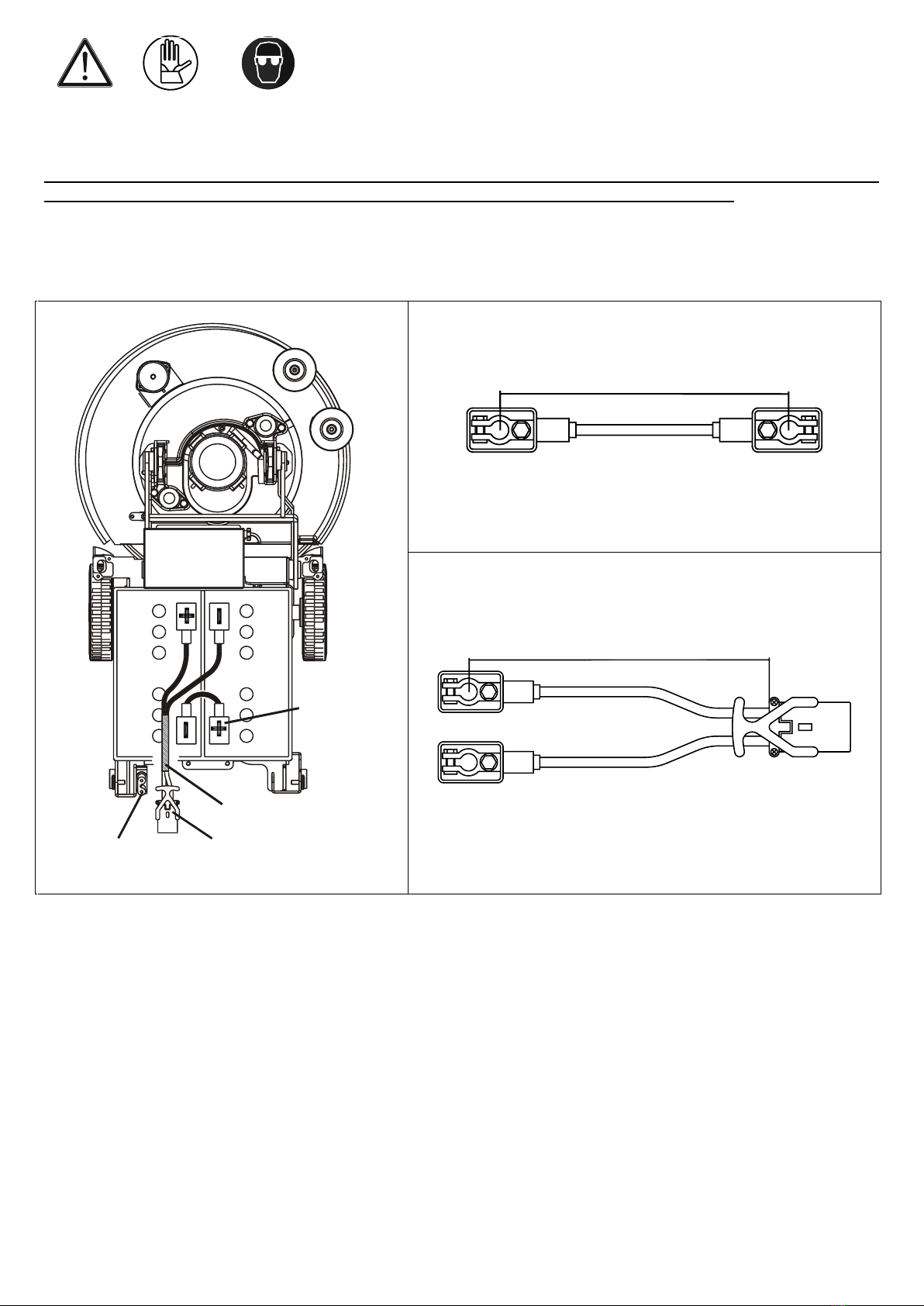
-Disconnect the battery cables before working on the electrical circuit.
-Avoid contact with battery acid
-Move carefully over uneven or crumbling paving and on slopes.
-Slow down on slopes and slipping surfaces
-Make sure the machine is not exposed to rain and weather conditions, whether in motion or still.
-Temperature of usage of the machine has to be kept within + 5 °C / + 40 °C.
-Humidity has to be kept within 30% / 80 %.
UPDATING OF THE USER’S MANUAL
When large-scale modifications are made to the machine or new parts are installed, the updated documentation must be
sent to the Dealer along with the purchased part or as an update of the manual
OBLIGATIONS OF THE EMPLOYER OR OWNER OF THE MACHINE
The employer or owner of the machine is responsible for giving the User’s Manual to all the personnel who are going to
have to use the machine.
The employer or owner of the machine also undertakes to update the manual with the documentation that the
Manufacturer will send if modifications are made to the machine.
RESPONSIBILITIES OF THE OPERATOR
- The operator is responsible for the day-to-day servicing of the machine
- The operator must care for the machine and keep it in good operating condition
- The operator must inform his or her superior or the technical department when scheduled maintenance is requested in
the case of damage or breakage.
- The operator must not carry people, animals or objects on the machine.
- When moving the machine, observe the safety measures for circulation.
- The machine cannot be used for toxic-harmful materials.
- Never let people get close to the machine’s sphere of action.
- Never leave the sweeper with the key and the emergency switch inserted.
- Engage the hand brake
- If the machine malfunctions, have a look at the procedures shown in the various chapters.
- Never collect pieces of string, wire or anything else that could damage the brushes by winding around them.
- Never suck up pieces of wood, plastic waste etc. as they may clog the vacuum pipe.
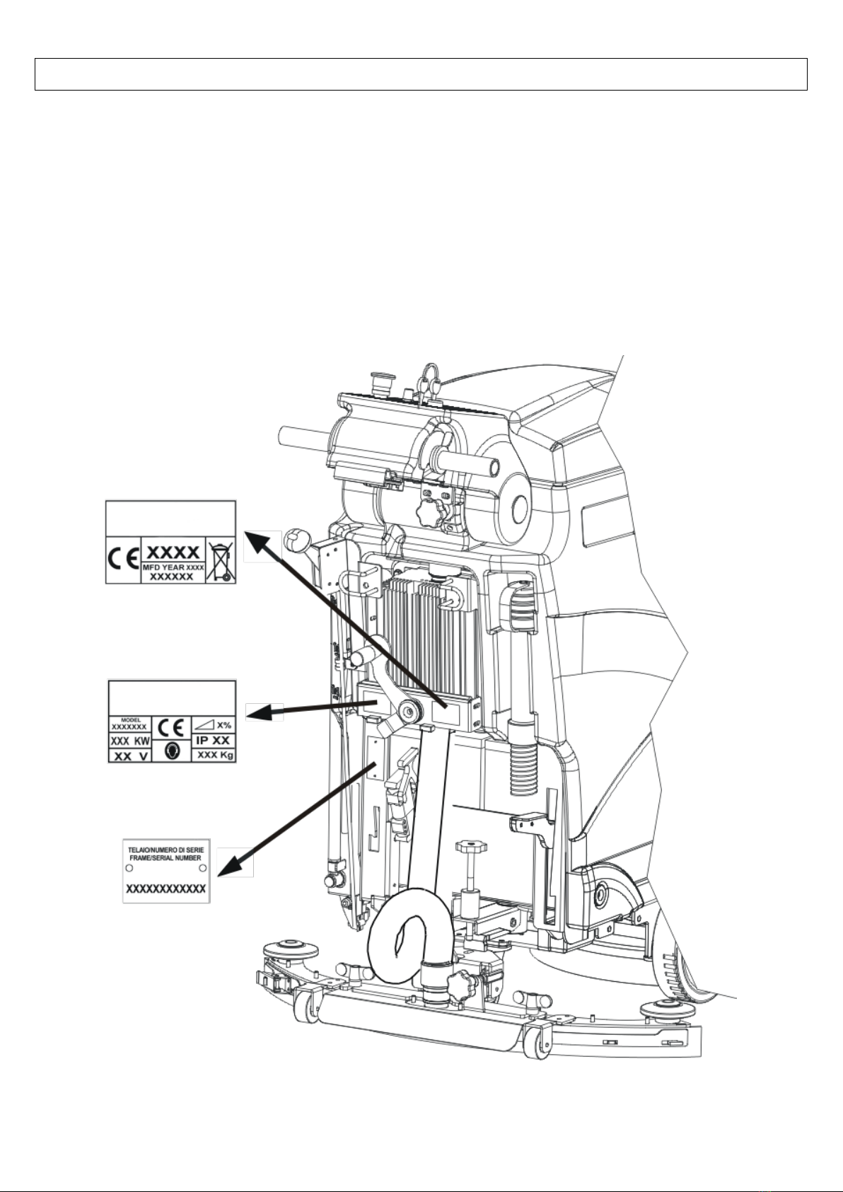
- Never remove or alter the plates on the machine.

7
DISPOSAL
SPENT OILS
Spent oils must not be thrown away into the environment under any circumstances.
They must be given to authorised Collectors in compliance with the regulations currently in force.
Temporary storage must be inside watertight containers with sealed lid to avoid contact with the environment and with
rainwater.
The filters must also be given to authorised collectors and temporarily kept like the oils.
DEAD LEAD BATTERIES
Dead batteries must be considered harmful toxic waste, they must be given only to Collectors with specific authorisation
(to be checked at the time of consignment).
SCRAPPING OF THE MACHINE
When the machine is to be scrapped, it is necessary to dispose of the materials the machine consists of, properly.
It is compulsory to give the machine to authorised collectors who will see to the proper disposal of: batteries, oils, filters,
plastics, metals, electric engines, electric cards etc. in accordance with the regulations currently in force.
DISPOSAL OF THE RECOVERY SOLUTION TANK
Prior to be moved on specific purification plants, the recovery tank solution is to be disposed of in the appropriate sites.
TRANSPORT- HANDLING
TRANSPORT
The machine must be fixed to a pallet to make it easier to transport and more secure.
At the reception of the machine, check that the packaging is in good conditions –in case of damage, report to the
forwarder.
PAY PARTICULAR ATTENTION WHILE TRANSPORTING THE MACHINE AT TEMPERATURES BELOW 0°C
AS TO PREVENT THE WATER INSIDE THE TANKS AND THE PIPES TO GET FROZEN.
DRAIN THE TANKS, REMOVE THE SCREEN OF THE CLEAN SOLUTION FILTER AND LET THE WATER
FLOW AWAY COMPLETELY OUT OF THE PIPES.
TRANSPORT- HANDLING
When the machine is moved from one place it is used in to another you are advised to:
- not load it on the vehicle with a forklift truck in order not to damage it
- lock the machine in place with the parking brake
- fix it well to the vehicle using belts, ropes and chains.
TRANSPORTING THE MACHINE BY MANUAL PUSHING
In case of transport by means of manual pushing –for machines featuring electronic traction only - the machine must be
pushed on at walking pace. Do not tow it with fork lifts.

8
Make sure that all the parts indicated in the following list are present before unpacking the machine:
Squeegee;
battery box;
battery jumper L = 25 cm, fitted with terminals and terminal covers;
battery cable L = 51.5 cm, fitted with connector, terminals and terminal covers;
battery charger on board the machine;
two 12 Volt dry charge batteries (optional).
NOTICE: brushes, discs and disc pad holders must be purchased separately.
Follow the instructions below to unpack the machine:
- connect the inclined ramp (position A) to the front part of the pallet, see figure 1;
- tilt the machine slightly and place the wheel lifting plate (position B), see figure 1;
- tilt the machine slightly again and place another wheel lifting plate from the other side of the machine (position C), see
fig. 2;
- remove the machine from the pallet along the inclined ramp (see fig. 3-4).
CAUTION: DO NOT USE A FORKLIFT TO REMOVE THE MACHINE FROM THE PALLET AS IT MAY
CAUSE DAMAGE TO THE MACHINE.
CAUTION: MOUNT THE BATTERIES ONLY AFTER REMOVING THE MACHINE FROM THE PALLET.
UNPACKING
1
2
3
4

9
LIFTING THE TANK
1
1
2
Follow the instructions below to lift the tank:
Bring the machine into a stop position in a flat surface area, put on the brake and turn the key into
position 0:
Unblock the tank by means of the two levers pos. 1 placed on both sides;
REACH THE DRIVER’S POSITION AND LIFT THE TANK BY THE GRIPS (POS. 2) PAYING ATTENTION
TO HANDLE IT WITH CARE WHILE PUTTING IT DOWN ON THE GROUND.

10
INSTALLING BATTERIES
CAUTION: USE PROTECTIVE GLOVES AND GOGGLES WHEN HANDLING BATTERIES, AVOIDING
ANY CONTACT WITH THE ACID INSIDE THE BATTERIES.
CAUTION: THE BATTERY CHARGER AND THE CONTROL BOARD ARE SET ACCORDING TO THE
TYPE OF BATTERIES SHOWN IN THE SHEET ATTACHED TO THE USER’S MANUAL.
IF YOU WANT TO MOUNT BATTERIES WITH A DIFFERENT AMPERAGE OR OF A DIFFERENT TYPE
(I.E. LEAD-ACID, AGM OR GEL) THE SETTING SHOULD BE DONE ON THE BATTERY CHARGER AS
WELL AS ON THE CONTROL BOARD ON THE MACHINE.CONTACT A RESELLER OR A TECHNICIAN
BEFORE MOUNTING THESE TYPES OF BATTERIES.
Refer to the specification sheet for battery types and sizes suitable for the machine.
FIG.C
FIG.B
2
3
FIG. A
L=250mm
FIG.B
L=515 mm
FIG.C
Follow the instructions below to mount the batteries to the machine:
park the machine on a flat surface, put on the brake (if available) and remove the key (if available);
Lift the tank following the instructions as indicated in the previous section of the present manual;
Place the batteries in the battery box. Make sure the poles are clean and apply a thin layer of petroleum jelly.
BE VERY CAREFUL NOT TO TURN OVER THE BATTERIES AS IT COULD CAUSE ACID TO LEAK
AND DAMAGE THE MACHINE.
Connect the jumper (fig. C) and the battery cable (fig. D) as indicated in figure B, make sure to tighten the screws on
the terminal clamps and place the terminal covers.
Connect the mobile connector (position 2 –fig. B) with the fixed connector (position 3 –fig. B) into the machine.

11
E 51 –M 510
1. Control board (TRAC and ECO versions)
2. Tank lid
3. Suction filter lid
4. Suction filter (TRAC and ECO versions)
5. Safety suction filter
6. Filter support
7. Drum of the clean water filter
8. Tank
9. Control panel
10. Suction lock float with filter
11. ECO-SYSTEM filter (ECO version)
12. ECO-SYSTEM safety filter (ECO version)
13. Squeegee slope adjustment hand-wheel
14. Tank unlock lever
15. Wheels
16. Squeegee pressure adjustment hand-wheel (TRAC
and ECO versions)
17. Brush plate lift pedal
18. Recovery tank outlet pipe
19. Instrument panel inclination adjustment hand-wheel
(TRAC and ECO versions)
20. Anti-crushing device (TRAC and ECO
versions)Level indicator pipe and solution tank outlet
drain
21. Battery charger
22. Squeegee lever
23. Battery mobile connector
24. Brake pedal (TRAC and ECO versions)
25. Squeegee
26. Detergent solution filter (TRAC and ECO versions)
27. Solenoid valves (TRAC and ECO versions)
28. Water pump (ECO version)
29. Drive gear motor (TRAC and ECO versions)
30. Brush
31. Vacuum motor
32. Batteries
33. Brush gear motor
34. Brush inclination adjustment knob (TRAC and ECO
versions)
35. Splashguard
36. Contactors
37. Fuse holder
38. Drive board (TRAC and ECO versions)

12
E61 –M610
1. Control board (TRAC and ECO versions)
2. Tank lid
3. Suction filter lid
4. Suction filter (TRAC and ECO versions)
5. Suction safety filter
6. Filter support
7. Drum of the clean water filter
8. Tank
9. Control panel
10. Suction lock float with filter
11. ECO-SYSTEM filter (ECO version)
12. ECO-SYSTEM safety filter (ECO version)
13. Squeegee inclination adjustment hand-wheel
14. Tank unlock lever
15. Wheels
16. Squeegee pressure adjustment hand-wheel (TRAC and
ECO versions)
17. Brush plate lift pedal
18. Recovery tank outlet pipe
19. Instrument panel inclination adjustment hand-wheel
(TRAC and ECO versions)
20. Anti-crushing device (TRAC and ECO versions)
21. Level indicator pipe and solution tank outlet drain
22. Battery charger
23. Squeegee lever
24. Battery mobile connector
25. Brake pedal (TRAC and ECO versions)
26. Squeegee
27. Detergent solution filter (TRAC and ECO versions)
28. Solenoid valves (TRAC and ECO versions)
29. Water pump (ECO version)
30. Drive gear motor (TRAC and ECO versions)
31. Brushes
32. Vacuum motor
33. Batteries
34. Brush gear motor
35. Splashguard
36. Contactors
37. Fuse holder
38. Drive board ( TRAC and ECO version)

13
PRIMARY FUNCTIONS AND CONTROLS
CONTROL PANEL
VERSIONS: E51 V2 TRAC - E61 V2 TRAC –M510 V2 TRAC–M610 V2 TRAC
E51 V3 ECO - E61 V3 ECO –M510 V3 ECO–M610 V3 ECO
4
1
----------
DRIVE OR REVERSE DRIVE CONTROL
Rotate the mechanism forward to drive the machine.
Rotate the mechanism backwards for reverse drive.
The speed of the machine will either increase or decrease progressively
when rotating the control progressively forward or backwards, it will go
from speed level 0 (machine in halt position) to the maximum speed set
with the potentiometer (position 4) located on the instrument panel.
2
----------
INSTRUMENT PANEL INCLINATION ADJUSTMENT HAND-
WHEEL
Enables the instrument panel to be positioned in three different
inclinations.
3
----------
ANTI-CRUSHING DEVICE
This is a safety device that halts the machine in reserve drive and makes it
go forward for a brief period in case the operator is trapped between the
machine and an obstacle behind him.
BRAKE PEDAL
VERSIONS: E51 V2 TRAC - E61 V2 TRAC –M510 V2 TRAC–M610 V2 TRAC
E51 V3 ECO - E61 V3 ECO –M510 V3 ECO–M610 V3 ECO
1
On the versions with electronic drive, the machine is
fitted with a parking brake and with an emergency
brake that operate on both front wheels.
To lock the machine push the brake pedal (position 1)
down and hook it into the preset housing.
The machine will then be locked.
Use the brake pedal (position 1) to unlock the
machine, unhook it from the housing and release it
slowly.
The machine will then be unlocked.

14
CONTROL PANEL
VERSIONS: E51 V1 BASIC –M510 V1 BASIC
1
2
3
4
GEL
GEL
WET
WET
5
1
WARNING SYMBOLS
The symbol on the left advices using the instruction manual at all times
for any information regarding the machine, whereas the symbol on the
right forbids the use of water on the instrument panel as there are
electrical parts
2
SUCTION FAN SWITCH
The suction fan is turned on by pressing the rocker switch into position 1.
The suction fan is turned off by pressing the rocker switch into position 0.
.
3
BRUSH SWITCH
The brush starts rotating by pressing the rocker switch into position 1.
The brush stops rotating by pressing the rocker switch into position 0.
4
EXHAUSTED BATTERY INDICATOR
The battery charge level is indicated when the brush is switched on.
The machine can keep operating as long as the green led light stays on.
The battery needs to be recharged when the orange led light comes on.
The machine needs to be switched off immediately if the red light comes
on; the exhausted battery may suffer irreversible structural damages if
continued to be used.
OPTIONAL –EXHAUSTED BATTERY INDICATOR WITH ACID/GEL CONTROL BOARD STATUS
LED AND BRUSHES IN HALT POSITION.
When the red light of the batteries charge indicator (pos. 4) is on, the brush stops rotating.
Charge the batteries to activate the brush.
NB –To switch from ACID to GEL mode, open the control panel and activate the lever
switch as shown in pos. 5

15
CONTROL PANEL
VERSIONS: E51 V2 TRAC - E61 V2 TRAC –M510 V2 TRAC –M610 V2 TRAC
1
----------
KEY-OPERATED SWITCH
The ignition sequence will start by rotating the key-operated
switch clockwise (position 1); a series of information will appear
on the display in successive order. THE BUTTONS ON THE
INSTRUMENT PANEL AND THE DRIVE CONTROLS
SHALL NEVER BE TOUCHED DURING THIS
SEQUENCE.
The charge level of the battery will appear on the display at the
end of the sequence, e.g. 100 - 90 - 80 etc.
The machine is ready to be used only at this point.
2
SUCTION FAN BUTTON
If the suction fan is switched off, this button can be used to turn it
on and a green light indicator will come on.
If the suction fan is switched on, this button can be used to turn it
off after a preset delay.
3
BRUSH RELEASE BUTTON
This button will enable the brush release sequence.
The led light will start blinking during this sequence.
This operation shall be carried out with the machine in halt
position and with the brush plate in raised position.

16
4
WARNING SYMBOLS
The symbol on the left advices using the instruction manual at all
times for any information regarding the machine, whereas the
symbol on the right forbids washing the instrument panel with
heavy water jets as there are electrical parts.
5
RED WARNING LIGHT: DRIVE ALARM
It shows any anomalies present on the motor’s drive board.
The number of blinks indicates the type of fault (see
troubleshooting table).
6
CHARGE BATTERY LEVEL INDICATOR AND DISPLAY
The charge level of the battery is displayed when the machine is
switched on (100 –90 –etc). When the battery charge level
reaches 20, the number on the display starts blinking and the
brush operation is disabled since a protection device is triggered
to prevent the battery from getting damaged, however the suction
and drive functions remain active.
At this point, the brush plate shall be raised and the floor shall be
dried quickly.
Upon reaching level 10, the number on the display shall start
blinking and the suction function will also be disabled, the drive
function will be the only active function. Lift the squeegee, go to
the tank drainage area and charge the batteries.
When 4 blinking dashes (----) appear on the display, the drive will
also be disabled as the battery reaches a minimum discharging
threshold. Therefore, the machine must be pushed over to the
tank drainage area and then pushed over to the battery charging
area.
7
HOUR METER BUTTON
Hold down this button to display the operating hours of the
machine.
8
.
BRUSH BUTTON
Press this button to enable the brush function; a green led light
will come on. The brush will start rotating when the machine is
set in motion.
When the control is released, the brush will rotate for other 3
seconds before stopping.
The solenoid valve is also connected to the brush function and
allows the user to automatically open or shut the flow of the
solution while the brush is rotating.
9
----------
EMERGENCY BUTTON
This button is used to halt the machine in case of emergency and
to lock all its functions.
Turn the knob clockwise to reset the power.
10
SPEED ADJUSTING POTENTIOMETER
To set up the maximum speed of the machine turn the knob
clockwise or counter-clockwise.

17
CONTROL PANEL
VERSIONS: E51 V3 ECO - E61 V3 ECO –M510 V3 ECO –M610 V3 ECO
1
----------
KEY-OPERATED SWITCH
The ignition sequence will start by rotating the key-operated
switch clockwise (position 1); a series of information will appear
on the display in successive order. THE BUTTONS ON THE
INSTRUMENT PANEL AND THE DRIVE CONTROLS
SHALL NEVER BE TOUCHED DURING THIS
SEQUENCE.
The charge level of the battery will appear on the display at the
end of the sequence, e.g. 100 - 90 - 80 etc.
The machine is ready to be used only at this point.
2
BRUSH RELEASE BUTTON
This button will enable the brush release sequence.
The led light will start blinking during this sequence.
This operation shall be carried out with the machine in halt
position and with the brush plate in raised position.
3
WATER ADJUSTMENT BUTTONS
Use the buttons + or –to set the maximum quantity of water to
use for the operation. Press the + button to increase the quantity
of water; the 5 green led lights on the panel come on
progressively one at a time.
Each led light is associated with a maximum pre-set quantity of
water.
Press the - button to decrease the quantity of water; the 5 led
lights will go out progressively one at a time. The water is shut
off when all the led lights are off.
The machine keeps memory of the adjusted quantity of water
even when switched off.

18
4
RED WARNING LIGHT: DRIVE ALARM
It shows any anomalies present on the motor’s drive board.
The number of blinks indicates the type of fault (see
troubleshooting table).
5
SUCTION FAN BUTTON
If the suction fan is switched off, this button can be used to turn
it on and a green light indicator will come on.
If the suction fan is switched on, this button can be used to turn it
off after a preset delay.
6
ECO-SYSTEM OPERATION BUTTON
Press this button to enable the ECO-SYSTEM.
The green light is on when the system is operating.
7
CHARGE BATTERY LEVEL INDICATOR AND DISPLAY
The charge level of the battery is displayed when the machine is
switched on (100 –90 –etc). When the battery charge level
reaches 20, the number on the display starts blinking and the
brush operation is disabled since a protection device is triggered
to prevent the battery from getting damaged, however the suction
and drive functions remain active.
At this point, the brush plate shall be raised and the floor shall be
dried quickly.
Upon reaching level 10, the number on the display shall blink
and the suction function will also be disabled; the machine drive
function will be the only active function. Lift the squeegee, go to
the tank drainage area and charge the batteries.
When 4 blinking dashes (----) appear on the display, the machine
drive will be also disabled as the battery reaches a minimum
discharging threshold. Therefore, the machine must be pushed
over to the tank drainage area and then pushed over to the battery
charging area.
8
HOUR METER BUTTON
Hold down this button to display the operating hours of the
machine.
9
.
BRUSH BUTTON
Press this button to enable the brush function; a green led light
will come on. The brush will start rotating when the machine is
set in motion.
When the control is released, the brush will rotate for other 3
seconds before stopping. The solenoid valve is also connected to
the brush function and allows the user to automatically open or
shut the flow of the solution when the brush is rotating.
10
----------
EMERGENCY BUTTON
This button is used to halt the machine in case of emergency and
to lock all its functions.
Turn the knob clockwise to reset the power.
11
SPEED ADJUSTING POTENTIOMETER
To set up the maximum speed of the machine turn the knob
clockwise or counter-clockwise.
12
WARNING SYMBOLS
The symbol on the left advices using the instruction manual at all
times for any information regarding the machine, whereas the
symbol on the right forbids the use of water on the instrument
panel as there are electrical parts.

19
SETTING UP THE MACHINE
MOUNTING THE SQUEEGEE
VERSIONS: E51 V1 BASE-E51 V2 TRAC-E51 V3 ECO-E61 V2 TRAC-E61 V3 ECO-
M510 V1 BASE-M510 V2 TRAC-M510 V3 ECO-M610 V2 TRAC-M610 V3 ECO
Follow the instructions below to mount the squeegee to the machine:
park the machine on a flat surface, put on the brake (if available) and remove the key (if available);
1
Position the squeegee lever into position 1 (raised
position).
A
B
C
Fit in the squeegee (position A) into the squeegee
support (position C).
Once the squeegee is fitted completely, secure the
knobs (position B).
1
2
Connect the squeegee hose from the straight side
(position 1) into the special seat located on the
bottom of the tank and press down hard until it fits
into place completely.
Mount the other end of the hose, from the roll-up
side (position 2) into the squeegee.
ADJUSTING THE SQUEEGEE
VERSIONS: E51 V1 BASE-E51 V2 TRAC-E51 V3 ECO-E61 V2 TRAC-E61 V3 ECO-
M510 V1 BASE-M510 V2 TRAC-M510 V3 ECO-M610 V2 TRAC-M610 V3 ECO
12
3
There are 2 types of adjustments that can be carried out on
the squeegee:
Inclination adjustment (ALL VERSIONS) with knob
(position 1).
It adjusts the inclination of the squeegee in order to have
a constant pressure over the entire length of the blade
(position 2).
Turn the knob counter-clockwise if there is too much
pressure on the outer points and little pressure on the
central area.
Turn the knob clockwise if there is little pressure on the
outer points and too much pressure on the central area.
To make the adjustment lower the squeegee, turn on the
suction fan and drive forward slowly. Examine the
pressure distribution on the blade and if necessary
correct the inclination as described above.
Pressure adjustment (EXCEPTION MADE FOR BASE VERSION) using the knob in position 3 (not included in
the basic version).
This allows for optimal pressure on the blade (position 2) which can be adjusted for each type of floor and for each
type of blade.
For rough floors or uneven floors, increase the pressure by turning the knob (position 3) clockwise.
For smooth floors, lower the pressure by turning the knob counter-clockwise.

20
MOUNTING THE ABRASIVE DISC ONTO THE DISC PAD HOLDER
The machine can operate with brushes or abrasive discs of various types mounted on special disc pad holders.
Follow the instructions below to mount the abrasive disc onto the disc pad holder:
1
2
3
4
Remove the disc lock (position 3) from the disc pad holder (position 1) by pressing the 2 ends of the spring catch
(position 4) against each other.
Position the abrasive disc (position 2) and centre it onto the disc pad holder (position 1).
Place the disc lock (position 3) on the centre and press down hard until the spring fits into place (position 4); this
operation can be carried out using the palm of your hand, or your foot if the disc pad holder is resting on the ground.
MOUNTING BRUSH OR ABRASIVE DISC ON MACHINE
VERSIONS: E 51 BASIC –M 510 BASIC
123
4
5
6
Follow the instructions below to mount the brush or disc
pad holder with abrasive disc:
Put the brush switch button and
the suction switch button into
position 0.
Lift the brush plate (position 4) with the pedal
(position 1).
Position the brush or disc pad holder (position 6)
under the brush plate lifting the splashguard (position
5) with one hand and centre it with the plate.
Slowly lower the brush plate with the pedal
(position 1).
Go into drive position and move the machine from
right to left and vice versa until the brush fits into
place correctly on the centre of the plate.
Push the brush switch button into position
1, the motor will start to run hooking on
the brush.
In order to avoid damaging the floor, as soon as the
brush is fastened it is advisable to halt the motor if
the machine is not used right away.
CAUTION: a screw (position 2) is located on the plate which enables the user to correct the drive, if not optimal, using a
standard 17 mm hexagon wrench (position 3).
It is advisable to make the adjustment while the machine is operating, with full water, with the squeegee in down position
and with the suction fan turned on.
N.B. if the screw (position 2) is fastened clockwise, the operating machine will tend to move to the right and if the screw
is fastened counter-clockwise, the machine will tend to move to the left.
Follow the instructions below to release the brush or disc pad holder with abrasive disc:
Turn the brush motor off by pressing the brush switch button into position 0.
Lift the brush plate with the pedal (position 1).
Get the brush or disc pad holder and rotate it clockwise until releasing the brush from the plate.

21
MOUNTING THE BRUSH OR ABRASIVE DISC ON MACHINE
VERSIONS: E51 V2 TRAC –E51 V3 ECO –M 510 V2 TRAC –M510 V3 ECO
Follow the instructions below to mount the brush
or disc pad holder with abrasive disc:
Turn off the machine and press the key into
position 0.
Lift the brush plate (pos.3) with the pedal (pos.1).
Put the inclination of the brush plate into 0 position by
turning the brush adjusting knob (pos.2) clockwise .
Position the brush or disc pad holder (pos.5) under the
brush plate lifting the splashguard (pos.4) and centre it
with the plate.
Slowly lower the brush plate with the pedal (pos.1).
Go into drive position and move the machine from right to
left and vice versa until the brush fits into place correctly
on the centre of the plate.
Rotate the key-operated switch (pos.1) and wait till the battery charge level is no more visible on
the display. At this point the starting-up sequence is complete.
Put the potentiometer for speed adjustment into min. position by pressing it towards the drawing
of the turtle, on the label.
Push the brush switch to activate the brush. The brush does not rotate when the green light is on.
Slowly push forward the drive control and release it as soon as the brush starts rotating. The brush motor will rotate for
2 seconds thus allowing for brush release. Repeat the same operation again if necessary.
With the brush removed form the plate, move the brush plate back into its original position by means of the knob pos.
2. Turn the knob clockwise (towards the sign + , on the label) for 4 rounds (inclination recommended).
Follow the instructions below to release the brush or disc pad holder with abrasive disc:
Press the brush button to deactivate the brush function.
Lift the brush plate with pedal (pos. 1).
Press the brush release button on the keyboard.
The releasing sequence will be activated and the brush will be released from the plate.
MOUNTING THE BRUSH OR ABRASIVE DISC ON MACHINE
VERSIONS: E61 V2 TRAC –E61 V3 ECO –M610 V2 TRAC –M610 V3 ECO
Follow the instructions below to mount the
brushes or disc pad holders with abrasive discs:
Turn off the machine and press the key into
position 0.
Lift the brush plate (pos.2) with the pedal (pos.1).
Position the brush or disc pad holder (pos.4) under the
brush plate lifting the splashguard (pos.3) and centre it
with the plate.
Slowly lower the brush plate with the pedal (pos.1).
Go into drive position and move the machine from right
to left and vice versa until the brush fits into place
correctly on the centre of the plate.
Rotate the key-operated switch (pos.1) and
wait till the battery charge level is no more
visible on the display. At this point the
starting-up sequence is complete.
This manual suits for next models
5
Table of contents
Other Eureka Scrubber manuals
Popular Scrubber manuals by other brands

Cleaning Machines
Cleaning Machines KF75B manual

Powr-Flite
Powr-Flite PFS32 Operator's manual

Nobles
Nobles Speed Scrub 2001 612946 Operator and parts manual

Tennant
Tennant T17 Series Instruction bulletin

American-Lincoln
American-Lincoln ALTO SMART 2000 ELECTRICAL TROUBLESHOOTING GUIDE

Tornado
Tornado 99695T Operation & maintenance manual