Eurocryor SPRING User manual

00763-00
OPERATING MANUAL FOR
SPRING
REFRIGERATED
DISPLAY
GB

2

3
INTRODUCTION AND QUALITY CONTROL
1. HANDLING AND STORAGE
2. DESCRIPTION OF COUNTER
3. REGULATION, USAGE AND PRESCRIPTION
4. ENVIRONMENTAL CONDITIONS
5. TECHNICAL DATA
6. INSTALLATION
7. DISPLAY CASE SET-UP
8. INDICATION FOR CLEANING AND MAINTENANCE
9. WASTE DISPOSAL
10.CONTROL PANEL
11.ELECTRICAL DIAGRAM
12.WARRANTY CONDITIONS
13.ADJUSTMENT AND MAINTENACE NOTES
14.SPARE PARTS

4
INTRODUCTION AND QUALITY CONTROL
EURO’CRYOR congratulates you on your choice to purchase our display
counter SPRING.
It is important to keep this manual with care for any further consultation.
It is recommended also, to pay particulary attention to the prescriptions
appearing in black character and underlined next to the below symbol:
INCOLLARE QUI
L’ETICHETTA PER IL
CONTROLLO DI
QUALITÁ

5
1. HANDLING AND STORAGE
Transport carried out without pallet or wooden box
•Insert the forklift truck prongs as indicated in the two following pictures. Keep a minimum distance
between the 600 mm. prongs making sure that they are properly centered in the middle of the
cabinet.
The transport operations for the 1250 mm long cabinet, have to be carried out as follows:
Lift-up the cabinet from the rear side as much to allow the forklift
truck prongs to slide underneath.
Lift-up the cabinet from the front side and at the same time push it
as much as possible over the forklift truck prongs, in order to place
it as shown in the picture.
Tilt the forklift truck prongs as shown in the picture, in order to
avoid that the display falls over.
Moving the counter by its sides is absolutely prohibited.

3
Transport carried out on pallet or wooden box
•Insert the forklift truck prongs in the shown
points.
•Insert the forklift truck prongs right to the
end to avoid overturning.
•There must be the greatest possibile
distance between the prongs to increase
the stability.
Storage
The storage temperature must not be higher than +55 Deg C. The display case must be stored away
from sunlight and bad weather.
If the display case must be stored for a long period before use, leave it in the original packing, which
provides an optimal protection.
•If the display case will be stored on
shelves, check the capacity of them.
•Store the display cabinet packed in the
wooden case / board on the shelves “1”,
if these have been used for transport.
•If on the contrary the wooden case /
board have not been used, the display
cabinet aluminium frame “2” must rest on
the rack shelf.
1
> 70cm
Lifting
-
up
points
2

4
2. DESCRIPTION OF COUNTER
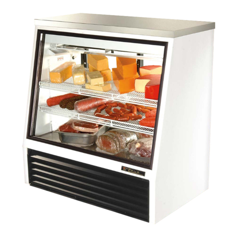
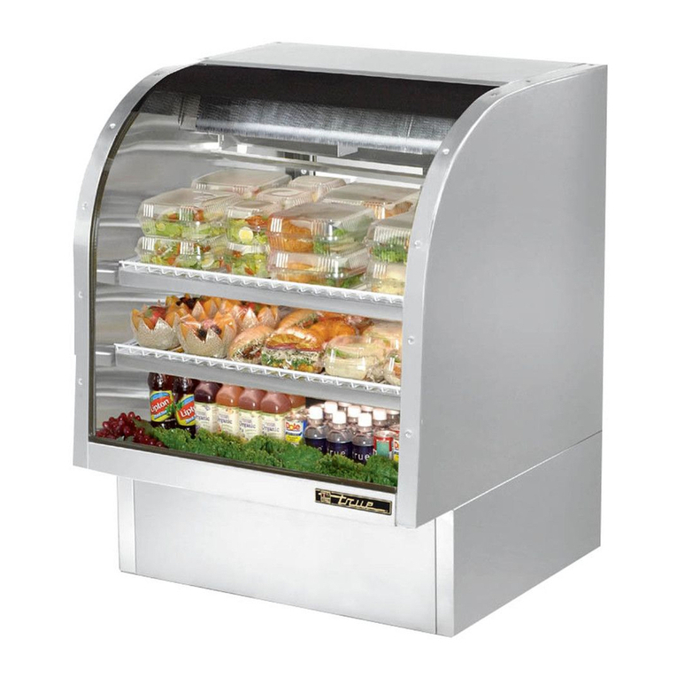
The refrigerated counter SPRING is suitable for the display and sale of deli products.
It is standard model, available in six linear lengths (1250, 1563, 1875, 2500, 3125, 3750) plus four
refrigerated corner models (938 + open corner, 938 + closed corner, 135°corner, 225°corner), all of
them with or without compressor unit.
Technical features:
•Goods temperature class: M2.
•Refrigerant: R404A.
•Ventilated cooled air circulation.
•Stainless steel inner carcase.
•Stainless steel display decks .
•Condensing water tray with automatic evaporation.
•Electronic panel.
•Back shelf with rounded edges
•Refrigerated storage with doors.
•Single lighting, protectid against bumps.
•Silver aluminium profile
•Front decoration available in three color.
•Tempered lifting-up curved glasses

5
MAX
LOAD
LINE
DATA
LABEL
POWER
SUPPLY CABLE
CONDENSATOR
BACK-SHELF PAPERHOLDER
REFRIGERATED
STORAGE UNIT
CONDENSING
WATER TRAY
ELECTRONIC
PANEL REAR CLOSURE
OPEN FRONT
GLASS
FRONT FACIA
DECORATION
LOWER
DECORATION
CANOPY
THERMOMETER
SIDE GLASS
CURVED
PANEL

6
3. REGULATIONS, USAGE AND PROHIBITIONS
Euro’Cryor’s display cases have been designed and produced exclusively for
the display of fresh foodstuffs and beverages inside the refrigerated sections.
it is absolutely forbidden to use the case to display pharmaceutical
products.
Before using the cabinet, read carefully the instructions quoted in this manual and
instruct the operator about the use.
Do not allow children or people with handicaps to use the display case without suitable
supervision.
Do not remove protection or panels which require tools to detach them.
It is absolutely forbidden any tampering or alteration of the product.
Any other use not described in this manuali is to be considered
dangerous and the manufacturer cannot be held responsible for any
damage caused by inappropriate, wrong or unreasonable use.
4. ENVIRONMENTAL CONDITIONS FOR INSTALLATION
The display case must be installed indoors and never exposed to rain or
bad weather conditions.
The display case must not be installed in places where there are
explosive materials.
Ensure that the display case is installed away from direct sunlight, concentrated lighting units and/or
sources of heat such as radiators, stoves and ovens; besides, avoid the installation near windows,
fan coils, air openings and fans.
It is absolutely forbidden to put any objects around the display case if they can obstruct the air
circulation on the condensing unit.
The non-respect of the above mentioned requirements can be the cause of a quick deterioration and
of an incorrect working of the display case, such as:
•A greater power consumption.
•Condensation on the cool surfaces (glasses or back shelf).
•Wrong food conservation.

7
(installation conditions example)
5. TECHNICAL FEATURES
5.1 General features
General features (25°C / 60% R.H.)
Operating temperature +2°C / +4°C
Climatic class (EN441) 3
Goods temperature class (EN 441) M2
Refrigeration type Ventilated
Evaporating temperature -10°C
Refrigerant R404A
Defrosting type Stop-compressor
Liquid pipe entry size 6 mm
Suction pipe exit size 12mm
Valve type To be soldered
Valve model Danfoss TUB/TUBE
Drain outlet size 40mm

8
5.2 Linear displays cabinets features
5.3 Angle display cabinets features
Electrical features (230Vac / 50HZ)
Lenght (mm)
90” DX/SX 135” 270 DX/SX 225”
Anti-mist fan (W) 40 40 40 40
Light (W) 72 88 90 92
Evaporator fans (W) 40 40 40 40
Mezzanine shelf light (option) (W) 72 88 90 92
Rated output without condensing
unit (W) 155 170 170 175
Condensing unit (W) 425 425 425 425
Rated output with condensing unit
(W) 580 595 595 600
Electrical features (230Vac / 50HZ)
Lenght (mm)
1250 1563 1875 2500 3125 3750
Anti-mist fan (W) 20 20 20 40 40 40
Canopy light (W) 44 46 73 90 119 146
Evaporator fans (W) 20 40 40 40 60 60
Mezzanine shelf light (option) (W) 44 46 73 90 119 146
Rated output without condensing
unit (W) 85 105 135 170 220 245
Condensing unit (W) 270 360 425 425 525 700
Rated output with condensing unit
(W) 255 465 560 595 745 945
Technical / Refrigerating features (25°C / 60% R.H. )
Lenght (mm)
1250 1563 1875 2500 3125 3750
Extraction rate (W) 325 405 490 650 815 975
Refrigerant mass (kg) 1.3 1.3 1.4 1.5 2 2
Compressor model
NB6452GK NB6165GK NE6210GK NE6210GK NE9213GK T6217GK
Display deck area (m²) 1.1 1.4 1.6 2.2 2.7 3.2
Display volume (m³) 0.2 0.252 0.29 0.4 0.49 0.58
Weight of counter (kg) with C.U. /
Without C.U. 150
125 180
155 210
190 270
250 340
315 400
375

9
6. INSTALLATION
The operations described in this chapter must be carried out exclusively
by qualified personnel.
6.1 Positioning
Remove the iron bars used for the transport.
Unwrap the cabinet with care, remove the protective thin plastic from the cabinet surfaces.
For a correct functioning, the display cabinet must be installed on a levelled floor (fig. A, B); in the
opposite case adjust the display cabinet feet fig. C).
Technical / Refrigerating features (25°C / 60% R.H. )
Counter model
90” DX/SX 135” 270 DX/SX 225”
Extraction rate (W) 500 615 630 685
Refrigerant mass (kg) 1.3 1.4 1.4
Compressor model NE6210GK NE6210GK NE6210GK NE6210GK
Display deck area (m²) 1.56 1.93 1.96 2.13
Display volume (m³) 0.28 0.34 0.35 0.38
Weight of counter (kg) with C.U. /
Without C.U. 290
260 310
280 360
330 250
220
Fig. BFig. A
Fig. C

10
6.1 Over structure assembly
3
Fig. D Fig. D-1
Fig. D-2 Fig. D-3
Fig. D-4 Fig. D-5
Fig. D

11
Fig. D-7
Fig. D-8
M6x10
Fig. D-9
Fig. D-11Fig. D-10
Fig. D-8, D-9
Fig. D-6

12
6.2 Side panel assembly
Fig. M-1, M-2
Fig. E Fig. E-1
Fig. E-2 Fig. E-3
Fig. E-4 Fig. E-5
Fig. E-5

13
6.3 Glass end installation
Fig. E-6 Fig. E-7

14
6.4 Central glass installation on Spring with non refrigerated angle

15
6.5 Multiplexing
When a display cabinet must be joined to another one (multiplexing), a kit with the necessary part is
supplied (see picture below)
N°1: insulating sponge.
N°2: box with screws and pins.
N°3: canopy union angle bar.
N°4: back side joining strip.
N°5: back shelf joining strip.
N°6: side covering strip.
See chapter 6.1
“Positioning”

16
3.9 x 9
4
NO/NEIN
SI/YES
OUI/JA

17
5
Table of contents
