euroline LVH-6 User manual

www.eurolite.de
USER MANUAL
BEDIENUNGSANLEITUNG
LVH-6
VIDEO SWITCH
© Copyright
Nachdruck verboten!
Reproduction prohibited!
LVH-6
AUTOMATIC VIDEO SWITCH
LVH-6 VIDEO SWITCH
LVH-6
AUTOMATIC VIDEO SWITCH
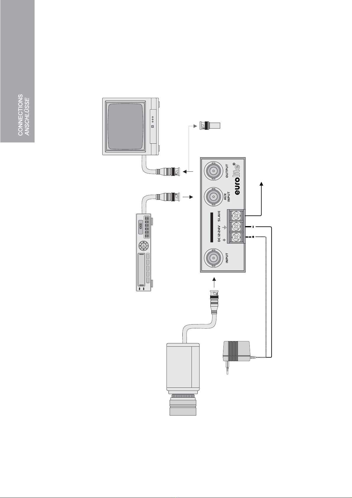
Video signal from equipment [NTSC/PAL]
Videosignal von Videogerät [NTSC/PAL]
12-24 V DC
Slave output to control other units
Slave-Ausgang zur Steuerung anderer Geräte
Alternate video source
Alternative Videoquelle
Acceptor or 75 terminator plugW
Endgerät oder 75 AbschlussW
POWER

LVH-6 VIDEO SWITCH
AUTOMATIC VIDEO SWITCH 2:1
The LVH-6 was designed to switch video signals from two sources to one output. The unit
utilizes a high quality RF relay to automatically switch to an alternate source when the
primary signal is lost. The slave output allows for controlling other units. Power connections
are made using block terminals. The unit responds to NTSC and PAL signals.
SAFETY INSTRUCTIONS
• Before your initial start-up, please make sure that there are no transport damages. Should
there be any, do not take the device into operation and immediately consult your dealer.
• Operate the device only after having familiarized with its functions. Do not permit operation
by persons not qualified for operating the device.
• Protect the device against humidity and heat. Keep away from heaters and other
heating sources!
• We recommend a frequent cleaning of the device. Disconnect from mains first. Use
a soft lint-free and moistened cloth. Never use alcohol or solvents!
• There are no serviceable parts inside the device. Maintenance and service operations are
only to be carried out by authorized dealers.
• Damage, caused by manual modifications on the device are not subject to warranty. If the
device is used for other purposes than originally intended or if it is not correctly connected,
the product may suffer damages and the guarantee becomes void.
• This product is allowed to be operated with 12-24 V DC. This device falls under protection
class 3 and was designed for indoor use only.
OPERATION
Prior to connecting switch off all units and do not turn them on again until you have made all
necessary connections.
1 Connect your signal source via a 75 coaxial cable with BNC plugs to the jack INPUT.This
input is 75 terminated.
2 Connect an alternative signal source via a 75 coaxial cable with BNC plugs to the jack
AUX INPUT.This input is terminated when it is connected to the output and is unterminated
when it is not in use.
3 Connect the unit to which the video signal is to be switched via a 75 coaxial cable with
BNC plugs to the jack OUTPUT. The output is designed to connect to a 75 load.
4 To power the unit 12-24 V DC are required. For this purpose, connect a power source (e.g.
power supply unit, battery) to the terminals DC 12-24. Always observe the correct
polarity.Connect the marked core to the left contact "+".
5 To control another unit with the LVH-6 connect it to the terminal SLAVE.
6 When the LVH-6 detects a video signal the jack INPUT is connected to the jack OUTPUT.
The unit responds to valid NTSC or PAL sync while ignoring 50 Hz and 60 Hz hum related
to induction artifacts. Weak signals as low as 0.5 V can be detected. When a valid signal is
detected, the relay also provides a ground connection to the SLAVE terminal, permitting
the unit to be connected as a video presence detector.
7 In the absence of video input at the jack INPUT or if power to the unit is interrupted, the jack
AUX INPUT is connected to the jack OUTPUT.
TECHNICALSPECIFICATIONS
Power supply: ..................12-24 V DC, 30 mA
2x video inputs: ................0.5-1 Vpp/75 BNC, ground referenced
1x video output:................BNC, ground referenced
Slave output:....................100 mA, block terminal
Dimensions (LxWxH):......76 x 41 x 31 mm
Weight: ............................7 g
W
W
W
W
W
W
Please note: Every information is subject to change without prior notice. 20.01.2009 ©

Bitte beachten Sie: Technische Änderungen ohne vorherige Ankündigung und Irrtum vorbehalten. 20.01.2009 ©
AUTOMATISCHER VIDEO-SCHALTER 2:1
Der LVH-6 dient dazu Videosignale von zwei verschiedenen Quellen auf einen Ausgang
umzuschalten. Fällt die ursprüngliche Signalquelle aus, findet automatisch eine Umschaltung auf
die zweite Quelle statt. Der LVH-6 nutzt ein hochwertiges HF-Relais für die Schaltung. Über einen
Slave-Ausgang können andere Geräte gesteuert werden. Die Spannungsversorgung erfolgt über
Schraubanschlüsse. Das Gerät erkennt NTSC- und PAL-Signale.
SICHERHEITSHINWEISE
• Bitte überprüfen Sie vor der ersten Inbetriebnahme, ob Transportschäden vorliegen. In diesem
Fall nehmen Sie das Gerät nicht in Betrieb und setzen sich bitte mit Ihrem Fachhändler in
Verbindung.
• Nehmen Sie das Gerät erst in Betrieb, nachdem Sie sich mit seinen Funktionen vertraut
gemacht haben. Lassen Sie das Gerät nicht von Personen bedienen, die sich nicht mit dem
Gerät auskennen.
• Schützen Sie das Gerät vor Feuchtigkeit und Nässe. Halten Sie das Gerät von Hitzequellen
wie Heizkörpern oder Heizlüftern fern.
• Das Gerät sollte regelmäßig von Verunreinigungen wie Staub usw. gereinigt werden. Trennen
Sie das Gerät zuvor vom Netz. Verwenden Sie zur Reinigung ein fusselfreies, angefeuchtetes
Tuch.Auf keinen FallAlkohol oder irgendwelche Lösungsmittel zur Reinigung verwenden!
• Im Geräteinneren befinden sich keine zu wartenden Teile. Wartungs- und Servicearbeiten sind
ausschließlich dem autorisierten Fachhandel vorbehalten!
• Schäden, die durch manuelle Veränderungen an diesem Gerät verursacht werden, fallen nicht
unter den Garantieanspruch. Wird das Gerät zweckentfremdet oder falsch angeschlossen,
kann dies zu Schäden am Produkt führen und der Garantieanspruch erlischt.
• Das Produkt ist für den Anschluss an 12-24 V DC zugelassen. Das Gerät ist nach Schutz-
klasse 3 aufgebaut und wurde ausschließlich zur Verwendung in Innenräumen konzipiert.
INBETRIEBNAHME
Schalten Sie alle Geräte vor dem Anschluss an die Verbindungsbuchsen aus und nehmen Sie sie
erst wieder in Betrieb, wenn Sie alle erforderlichenAnschlüsse vorgenommen haben.
1. Schließen Sie Ihre Signalquelle über ein 75 Koaxialkabel mit BNC-Steckern an die Buchse
INPUT an. Die Eingangsbuchse INPUT ist mit 75 abgeschlossen.
2. Schließen Sie eine alternative Signalquelle über ein 75 Koaxialkabel mit BNC-Steckern an den
Hilfseingang AUX INPUT an. Der Eingang AUX INPUT ist abgeschlossen, wenn er mit dem
Ausgang verbunden ist, wird er nicht benutzt, ist er nicht abgeschlossen.
3. Schließen Sie das Gerät, auf das das Videosignal geschaltet werden soll, über ein Kabel mit
BNC-Steckern an die Buchse OUTPUT an. Der Ausgang kann mit einer 75 Last belastet
werden.
4. Zur Spannungsversorgung des Geräts werden 12-24 V DC benötigt. Verbinden Sie dazu eine
Spannungsquelle (z.B. Netzteil, Batterie) mit den Klemmen DC 12-24. Achten Sie dabei
unbedingt auf die richtige Polarität. Schließen Sie die gekennzeichnete Ader an den linken
Kontakt "+" an.
5. Über den Slave-Ausgang lassen sich andere Geräte steuern. Schließen Sie dazu die
Relaiskontakte dieses Gerät an die Klemme SLAVE an.
6. Wenn der LVH-6 ein Videosignal erkennt, wird die Eingangsbuchse INPUT mit der
Ausgangsbuchse OUTPUT verbunden. Die Videoerkennung spricht auf gängige NTSC- oder
PAL-Syncronistation an und nicht auf 50 Hz und 60 Hz Brummen. Das Gerät erkennt auch
schwache Signale mit 0,5 V. Wenn ein gängiges Signal erkannt wird, stellt das Relais auch eine
Erdverbindung mit dem Slave-Ausgang her, wodurch der LVH-6 als Video-Erkennungsschaltung
verwendet werden kann.
7. Wenn am Eingang INPUT kein Videosignal vorhanden ist oder wenn die Stromversorgung zum
LVH-6 unterbrochen wird, wird der EingangAUX INPUT mit demAusgang OUTPUT verbunden.
W
W
W
W
W
TECHNISCHE DATEN
Spannungsversorgung: .......12-24 V DC, 30 mA
2x Video-Eingänge: .............0,5-1 Vss/75 BNC, geerdet
1x Video-Ausgang: ..............BNC, geerdet
Slave-Ausgang:...................100 mA, Schraubanschluss
Maße (LxBxH): ....................76 x 41 x 31 mm
Gewicht:..............................7 g
00042746.DOC, Version 1.0
LVH-6 VIDEO SWITCH
Table of contents
Languages:
Popular Switch manuals by other brands


S+S Regeltechnik
S+S Regeltechnik PREMASREG 716x Series Operating Instructions, Mounting & Installation

TRENDnet
TRENDnet TE100-DX4PCI user guide

IDEM SAFETY SWITCHES
IDEM SAFETY SWITCHES MPR operating instructions

AirLive
AirLive POE-GSH1008R-130 user manual

Planet
Planet HPOE-1200G user manual

3One data
3One data ICS5000-E24GP4GS Quick installation guide

Tripp Lite
Tripp Lite U227-FT3-R owner's manual

AirLive
AirLive Ether-FSH2422W Quick setup guide

HIK VISION
HIK VISION DS-3E0516 Series quick start guide

Sensor Switch
Sensor Switch JOT WSXA troubleshooting guide

Black Box
Black Box LH8000A-M Technical specifications

Tripp Lite
Tripp Lite Minicom Smart 108 IP quick start guide