Eurolux ERC60X Guide

ERC60X
ERC90X
INSTALLATION, OPERATION
& MAINTENANCE INSTRUCTIONS
FOR EUROLUX RANGEHOOD
Model:
ERC60X
ERC90X
AUSTRALIAN & NEW
ZEALAND PRODUCT
WARRANTY

INSTALLATION, OPERATION AND MAINTENANCE INSTRUCTIONS FOR EUROLUX
RANGEHOOD
ERC60X/ERC90X
CONGRATULATIONS
Welcome to the Eurolux Kitchen Community and thank you for choosing one of our many fantastic appliances. Before you
use the rangehood we strongly recommend that you read through the whole user manual which provides the description of
this product and the proper use of its functions. To avoid the ever-present risks involved with using an electrical appliance it
is vital that the appliance is installed correctly and that you read the safety instructions carefully to avoid misuse and
hazards.
CONTENTS
IMPORTANT SAFETY INSTRUCTIONS ..........................................................................................................................1
APPLIANCE DETAILS....................................................................................................................................................2
INSTALLATION INSTRUCTIONS....................................................................................................................................3
INSTALLATION INSTRUCTIONS....................................................................................................................................5
OPERATING INSTRUCTIONS........................................................................................................................................6
MAINTENANCE AND CLEANING..................................................................................................................................7
TROUBLESHOOTING ...................................................................................................................................................9
AUSTRALIAN & NEW ZEALAND PRODUCT WARRANTY ............................................................................................10
It is important that you retain these instructions, proof of purchase as well as other important documents
about this product for future reference.
Due to continual product development, Eurolux reserves the right to alter specifications or appearances
without notice.
Remove all packaging and dispose responsibly – recycle where facilities are available.

1
IMPORTANT SAFETY INSTRUCTIONS
Important:
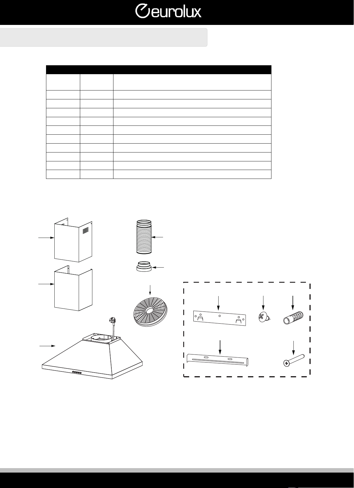
Please read the entire instructions before installing the rangehood. Check appliance for damage or missing parts (if
damaged, do not install).
•Always switch power off prior to installation.
•All electrical work must be done in accordance with local and national electrical codes as applicable.
•For safety, this product must be earthed.
•A power outlet should be within 1m of the power cord exit from the rangehood.
•The socket must be accessible and enable the end user to isolate the rangehood from the power for the purpose
of internal cleaning or maintenance.
•Stainless steel or powder coat is very easily damaged during installation if abraded or knocked by tools.
•Protect the rangehood with the cardboard box or plastic bag during installation.
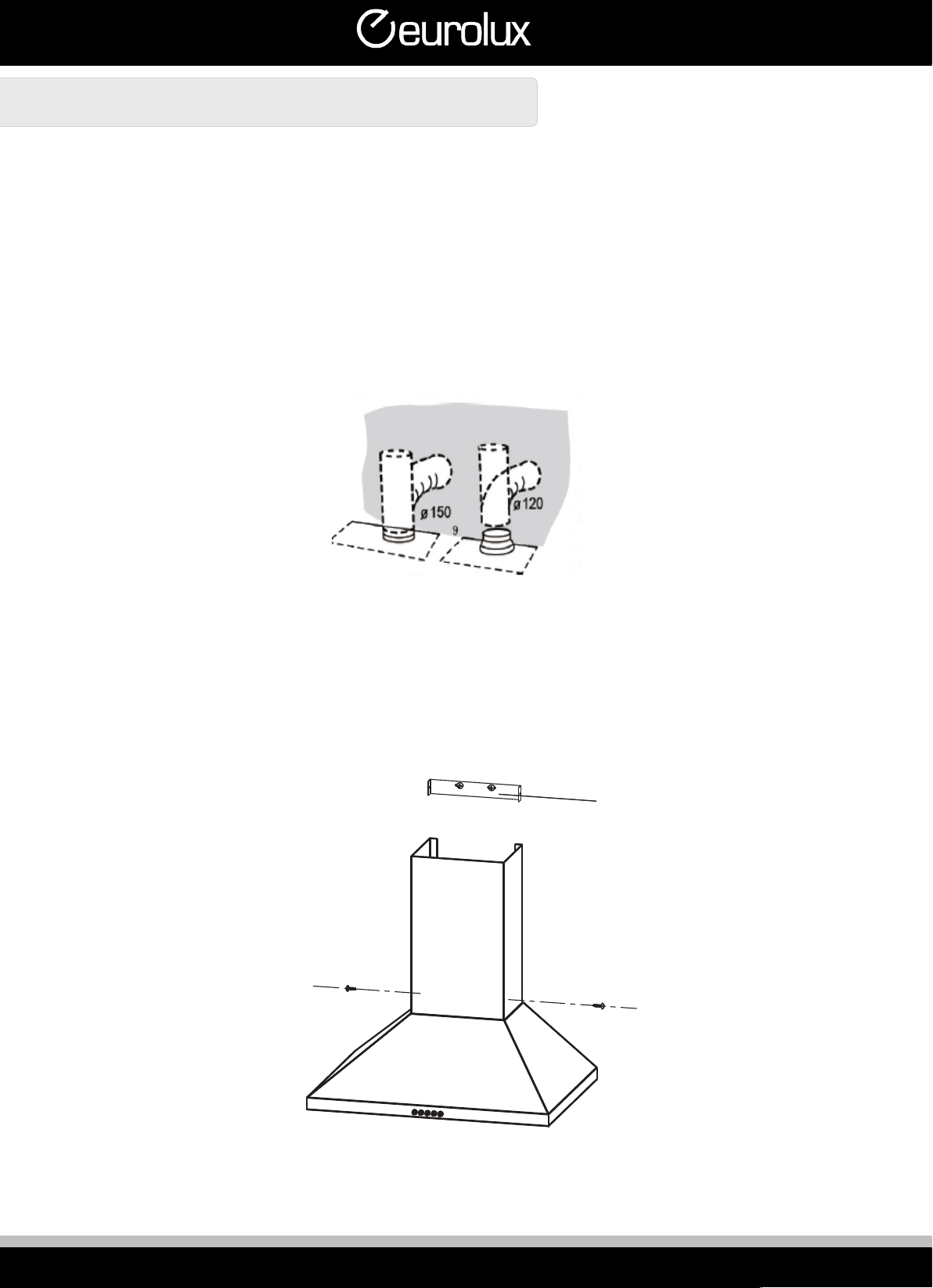
•All ducting must comply with local requirements and building codes.
•Suitable fixings will be required to mount this rangehood.
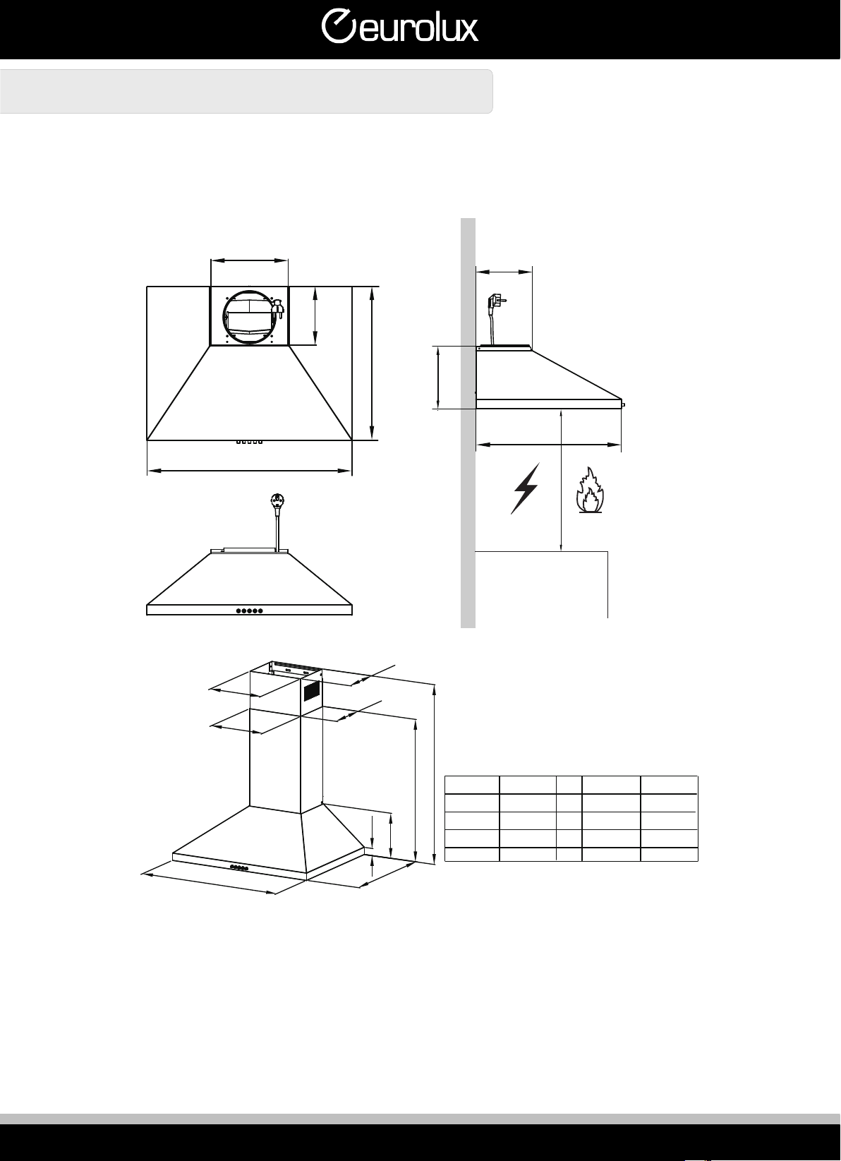
•The minimum distance between an electric or gas hob surface and the lowest part of the rangehood is 650mm. If
the instructions for the hob specify a greater distance, this has to be taken into account.
•Stainless steel is very easily damaged during installation if abraded or knocked by tools. Protect the rangehood
with the cardboard box or plastic bag during installation.
•All electrical work must be done by a registered electrician in accordance with local and national electrical codes as
applicable. For your safety, this product must be earthed.
•If the supply cord of this equipment is damaged, it must only be replaced by the manufacturer or its service agent
or a similarly qualified person in order to avoid a hazard.
•This rangehood is designed for indoor use only and must be in a dry location.
•Disconnect the power supply when any maintenance is carried out, including changing light bulbs or inspecting
filters. Do not touch lights after appliance use.
•This appliance is not intended for use by persons (including children) with reduced physical, sensory or mental
capabilities, or lack of experience and knowledge, unless they have been given supervision or instruction
concerning use of the appliance by a person responsible for their safety.
•Young children should be supervised to ensure that they do not play with the appliance.
•There shall be adequate ventilation of the room when the rangehood is used at the same time as appliances
burning gas or other fuels.
•There is a fire risk if cleaning is not carried out in accordance with the instructions. You must read the details
concerning the method and frequency of cleaning.
•Do not flambé under the rangehood.
•Exhaust air must not be discharged into an existing flue which is used for exhausting fumes from appliances
burning gas or other fuels.
•The minimum distance between the hob surface and the lowest part of the rangehood is 650mm. If the
instructions for the hob specify a greater distance, this has to be taken into account.
•Attention should be given to ensure that any applicable regulations concerning the discharge of exhaust air is
fulfilled. If recirculating, take care no ventilation becomes blocked or partially blocked.
•CAUTION: Accessible parts may become hot when used with cooking appliances.
•WARNING: Failure to install the screws or fixing devices in accordance with these instructions may result in an
electrical hazard.
•It is recommended that the rangehood is started before cooking, and allowed to run for a period after cooking has
finished (to remove vapours & odours). Turn off when not in use.
•The rangehood is intended to be installed over a hob with no more than four elements.

2
APPLIANCE DETAILS
Reference
Qty
Product components
1 1
Hood body, complete with controls, light, blower, and
filter
2.1
1
Lower decorative chimney
2.2
1
Upper decorative chimney (optional)
3
1
Flange (Optional)
4
1
Exhaust pipe
5
2
The activated charcoal filter (optional)
10
7
Screws 5 x 50
11
7
Wall plugs
12
6
Screws 4,2 x 9,5
20
1
Hood fixing bracket
21
1
Chimney fixing bracket (optional)
2.2 4
3
2.1 5
1
20 12 11
21 10

3
INSTALLATION INSTRUCTIONS
225 171
472
600/900
Min.
650mm Min.
650mm
171
30 472
238
A
B258
226
229
600/900
170
172
472
unit:mm
Option A B
1
2
Chimney
3
Height
4
400+0628 /
400+300 628 670-910
400+390 628 670-1000
500+490 728 770-1200
628
628-910
628-1000
728-1200

4
INSTALLATION INSTRUCTIONS
WALL DRILLING AND BRACKET FIXING
As a first step, proceed with the following drawings:
•A vertical line up to the ceiling or up to the upper limit, at the center of the area in which the hood is to be fitted.
•A horizontal line A at 920-1020 mm above the cooker top.
•A horizontal line B at a X mm above the horizontal line A.
•A horizontal line C at a 190mm below the horizontal line A.
Mark Points:
•Mark a point (1) on the horizontal line A, 80 mm to the vertical reference line.
•Repeat this operation on the other side and on the vertical reference line , checking that the three marks are
levelled.
•Mark a point (2) on the horizontal line B, 40 mm to the vertical reference line.
•Repeat this operation on the other side , checking that the two marks are leveled.
•Mark a point (3) on the horizontal line C, 170 mm to the vertical reference line.
•Repeat this operation on the other side , checking that the two marks are leveled.
Fix the brackets :
Drill holes at the marked points with a ɸ10 mm drill bit.
•Insert the Wall Plugs 11 into the holes.
•Fix the hood fixing bracket 20 with 3 screws 10 (5 x 50) at the horizontal line A.
•Fix a Chimney fixing bracket 21 with 2 screws 10 (5 x 50) at the horizontal line B.
Hook the hood body:
•Hook the hood body to the bracket 20.
•Level the hood body itself.
•Remove the filter from the inside of the hood body, fix the screws 10 to Wall Plugs 11 at the points (3).
Right Wrong

5
INSTALLATION INSTRUCTIONS
CONNECTIONS
DUCTED VERSION AIR EXHAUST SYSTEM
When installing the ducted version, connect the hood to the chimney using either a flexible or rigid pipe ɸ150 or ɸ120
mm, the choice of which is left to the installer.
•To install a ɸ120 mm air exhaust connection, insert the reducer flange 3 on the hood body outlet.
•Fix the pipe 4 in position using sufficient pipe clamps (not supplied).
•Remove possible charcoal filters.
CHIMNEY ASSEMBLY
Lower Decorative Chimney
Fix the Lower Decorative Chimney to the hood body with 2 screws 12 (4.2 x 9.5) supplied with the hood.
B

6
Upper Decorative Chimney
Fix the upper chimney onto the bracket 21 with 2 screws 12 (4.2 x 9.5) supplied with the hood.
OPERATING INSTRUCTIONS
Speed adjustment:
ON/OFF LIGHTING SWITCH: Press on this switch to turn on the
lights, and press again to turn them off.
OFF MOTOR SWITCH: Press on this switch to stop the motor
operation.
SPEED SWITCH: Press on this switch, the motor runs at LOW
speed.
SPEED SWITCH: Press on this switch, the motor runs at
MEDIUM speed.
SPEED SWITCH: Press on this switch, the motor runs at HIGH
speed.

7
MAINTENANCE AND CLEANING
GREASE FILTERS
CLEANING METAL SELF-SUPPORTING GREASE FILTERS
•The filters must be cleaned every 2 months of operation, or more frequently for particularly heavy usage, and can
be washed in a dishwasher.
•Pull the comfort panels to open them.
•Remove the filters one by one pushing them towards the back side of the hood unit and simultaneously pulling
downwards.
•Any kind of bending of the filters has to be avoided when washing them. Before fitting them again into the hood
make sure that they are completely dry. (The color of the filter surface may change throughout the time but this
has no influence to the filter efficiency).
•When fitting the filters into the hood pay attention that they are mounted in correct position the handle facing
outwards.
ACTIVATED CHARCOAL FILTER (RECIRCULATION VERSION)
REPLACING THE ACTIVATED CHARCOAL FILTER
These filters are not washable and cannot be regenerated, and must be replaced approximately
every 4 months of operation, or more frequently with heavy usage.
•Remove the metal grease filters
•Remove the saturated activated charcoal filter.
•Fit the new filters.
•Replace the metal grease filters.
REMOVE
FIX
FIX
REMOVE

8
REPLACING THE LIGHT
•You cannot replaced the light bulbs, the entire light module has to be replaced.
•When changing the light modules, the contacts are live.
•Before changing the light module(s), unplug the appliance from the mains or switch off the circuit breaker in the
fuse box.
•Remove the grease filter .
•Disconnect the terminal of LED light.
•Press LED light on the back of the front plate, take the LED light out.
•Replace the lamp(commercially available LED lamp (max.1.5w).
Reinstall LED light module
•Press LED light on the front of front plate, install the LED light on the front plate.
•Connect the terminal of LED light and light leads.
•Reinstall the grease filter.
Max Power Voltage Picture Lamp Cap ILCOS D code
1.5W DC 12 V —— DSS-1.5-S-33.2
/120
Lamp type
Square / Dimesion:
33.2mm x 120mm

9
TROUBLESHOOTING
Fault
Cause
Solution
Light on, but
motor does not
work
The blades are blocked.
Check the blades.
The capacitor is damaged.
Replace capacitor.
The motor is damaged.
Replace motor.
The internal wiring of motor is cut off/ disconnected. An
unpleasant smell may be produced. Replace motor.
Both light and
motor do not
work
Apart from the above mentioned, check the following:
Light damaged.
Replace lights.
Power cord loose.
Connect the wires as the electric diagram.
Oil leakage
Outlet and the air ventilation entrance are not tightly
sealed. Take down the outlet and seal with glue.
Vibration
The blade, if damaged, can cause vibrating.
Replace the blade.
The motor is not tightly fastened.
Fasten the motor tightly.
The cooker hood is not tightly fixed.
Fixed the cooker hood tightly.
Insufficient
suction
The distance between the cooker hood and the cooker
top is too large. Readjust the distance.
Too much ventilation from open doors or windows.
Choose a new place to install the appliance
or close some doors / windows.
The machine
inclines
The fixing screws are not tight enough.
Tighten the fixing screw and make it
horizontal.
The hanging screws are not tight enough
Tighten the hanging screw and make it
horizontal.

10
AUSTRALIAN CUSTOMERS
Our goods come with guarantees that cannot be excluded under the Australian Consumer Law. You are entitled to a replacement or
refund for a major failure and for compensation for any other foreseeable loss or damage. You are also entitled to have the goods
repaired or replaced if the goods fail to be of acceptable quality and the failure does not amount to a major failure.
NEW ZEALAND CUSTOMERS
Nothing herein contained shall be construed in any way as excluding or limiting your rights under the Consumer Guarantee Act 1993.
OUR WARRANTY
Subject to the following conditions, this product is also covered by the manufacturer’s THREE (3) YEAR WARRANTY from the date of
purchase, covering all parts and labour (Our W arranty). Our Warranty (which is subject to the conditions below) covers rectification free
of charge of any fault arising from defective materials or components, or faulty workmanship. The product will be repaired or replaced at
the option of Eurolux. Our Warranty is subject to the product being used for single family domestic household use.
Our Warranty operates in addition to (and does not exclude, restrict or modify) any rights or remedies to which you may already be
entitled to under the Australian Consumer Law or any consumer guarantees law relating to this product.
WHAT IS COVERED: By Our Warranty
During the warranty period, Eurolux or its authorised Service Centre will at no extra charge, if your appliance is readily accessible without
the need of special equipment and subject to the terms and conditions of this warranty, repair or replace any parts which it considers
defective.
WHAT IS NOT COVERED BY OUR WARRANTY
1. Incomplete or improper installation.
2. Normal wear and tear e.g. cleaning, light globes,filters etc.
3. Failure resulting from power surges and electrical storms.
4. Insect or vermin infestation.
5. Unauthorised repairs or use of non genuine Eurolux parts.
6. Any failure caused by the product not being used in accordance with the instruction and installation manual provided with
the product.
7. Misuse or abuse, including failure to properly maintain or service.
8. The clearing of blockages in pumps and hoses.
9. Damage which occurs during delivery or installation.
10. Claims to product surface coating due to liquid or solid spill-overs, accidental damage or damage from cleaning products
not recommended by Eurolux.
HOW TO CLAIM OUR WARRANTY
Please refer to our website address below for Everdue in Australia or New Zealand to register your warranty online. If you
are contacting Eurolux regarding any warranty claims and spare part enquiries, please make sure you have the following
information on hand:
1. Product Name/Model Number
2. Serial Number
3. Purchase Date (as per invoice, or proof or purchase
4. Purchased from
5. Warranty Registration Number
All Warranty Claims and Spare Parts Inquiries:
In Australia:
Telephone: 1300 355 541
A division of Shriro Australia Pty Ltd
2-34 Davidson Street, Greenacre, NSW 2190
In New Zealand:
Telephone (09) 415 6000
A division of Monaco Corporation
231 Bush Rd, Albany, North Shore City, Auckland, 0632
AUSTRALIAN & NEW ZEALAND PRODUCT WARRANTY


EASY DECISION
A division of Shriro Australia Pty Limited
2-34 Davidson Street, Greenacre NSW 2190
AUSTRALIA: 1300 355 541
www.shriro.com.au
NEW ZEALAND: (09) 415 6000
www.monacocorp.co.nz
IM Ref: ERC60X and ERC90X 3/2021/31FC
FOR INDOOR USE ONLY
This manual suits for next models
1
Table of contents
Other Eurolux Ventilation Hood manuals