Eurolyser CUBE-S User manual
2ad89664-e5f4-4907-bab1-9f7c76e7d9ef / DP10.0 / 2016-07-04 Page 1 of 43 Eurolyser Diagnostica GmbH
User Manual
Eurolyser Diagnostica GmbH
Bayernstraße 11a
5020 Salzburg, AUSTRIA
Tel: +43 662 432100
Fax: +43 662 432100 50

2ad89664-e5f4-4907-bab1-9f7c76e7d9ef / DP10.0 / 2016-07-04 Page 2 of 43 Eurolyser Diagnostica GmbH
SYMBOLS & ABBREVIATIONS
The following symbols and abbreviations are used in the product labeling and instructions for the
Eurolyser laboratory photometer.
Symbol / Abbreviation Explanation
Conformity marking according to the directive 2004/108/EC of the European
Parliament and of the European Council
Catalogue number / Order number
Lot number
Serial number
Bluetooth
Connection
Power Supply / Device Readiness
Use by
Temperature limitations
Relative humidity limitations
Manufacturer
Production date
Sterile
Warnings and precautions, see accompanying documents
Operator's action
Refer to the user’s manual and follow the instructions
Do not dispose with household waste
ERS TC
ERS Testing Cartridge

2ad89664-e5f4-4907-bab1-9f7c76e7d9ef / DP10.0 / 2016-07-04 Page 3 of 43 Eurolyser Diagnostica GmbH
LED
Light Emitting Diode
PC
Personal Computer
ID
Identification
HIS / LIS
Hospital Information System / Laboratory Information System
AC
Alternating Current
DC
Direct Current
RFID
Radio Frequency Identification
Table 1: Product Labelling and User Manual Symbols

2ad89664-e5f4-4907-bab1-9f7c76e7d9ef / DP10.0 / 2016-07-04 Page 4 of 43 Eurolyser Diagnostica GmbH
TABLE OF CONTENTS
SYMBOLS & ABBREVIATIONS .................................................................................................................................................2
TABLE OF CONTENTS..............................................................................................................................................................4
INTRODUCTION......................................................................................................................................................................7
Intended use of the Eurolyser CUBE-S/CUBE Laboratory Photometer .......................................................................................7
About this user manual ..............................................................................................................................................................7
Inspecting the package contents ...............................................................................................................................................7
CUBE-S/CUBE packaging............................................................................................................................................................8
SYSTEM DESCRIPTION............................................................................................................................................................9
Description of the Eurolyser CUBE-S/CUBE Analyser .................................................................................................................9
CUBE-S/CUBE Instrument Interfaces..........................................................................................................................................9
Indicator lights .........................................................................................................................................................................10
How to handle the Eurolyser CUBE-S/CUBE Laboratory Photometer ......................................................................................10
How the Eurolyser CUBE-S/CUBE Laboratory Photometer works ............................................................................................11
Manufacturer calibration.........................................................................................................................................................11
PICTOGRAMMS / BUTTON SYMBOLS ...................................................................................................................................12
Tablet PC symbols and their functions .....................................................................................................................................12
GETTING STARTED ............................................................................................................................................................... 13
The proper placement of the CUBE-S/CUBE Laboratory Photometer ......................................................................................13
Transport lock ..........................................................................................................................................................................13
Connecting the power supply...................................................................................................................................................13
The Tablet PC ...........................................................................................................................................................................14
Starting & Operating the Tablet PC .........................................................................................................................................14
The Eurolyser CUBE-S/CUBE Launcher .....................................................................................................................................14
Changing the language of the Eurolyser CUBE-S/CUBE application ........................................................................................14
How to switch the Eurolyser CUBE-S/CUBE Laboratory Photometer ..............................................................................ON
15
The automatic start-up and warm-up processes .....................................................................................................................15
CONFIGURING THE EUROLYSER CUBE-S/CUBE .....................................................................................................................16
Setting normal values and limits..............................................................................................................................................16
Setting units .............................................................................................................................................................................17

2ad89664-e5f4-4907-bab1-9f7c76e7d9ef / DP10.0 / 2016-07-04 Page 5 of 43 Eurolyser Diagnostica GmbH
Configuring inputs (Sex, Sampletype, Hematocrit, Operator)..................................................................................................17
Configuring interfaces..............................................................................................................................................................18
OPTIONAL EQUIPMENT........................................................................................................................................................20
Printer, barcode scanner or PC.................................................................................................................................................20
Connecting a barcode scanner.................................................................................................................................................20
Using a barcode scanner to scan patient ID and/or operator information..............................................................................21
How to wake the CUBE-S/CUBE Analyser up or switch it OFF..................................................................................................21
TEST PROCEDURES ...............................................................................................................................................................22
Overview of the testing and measuring procedures ................................................................................................................22
Operating safety precautions...................................................................................................................................................23
Analysing a patient sample......................................................................................................................................................24
Viewing and processing test results .........................................................................................................................................26
Eurolyser Online Services (EOS) ...........................................................................................................................................27
EOS Synchronization ................................................................................................................................................................28
Synchronizing all test results ...............................................................................................................................................28
Eurolyser Online Services Registration ................................................................................................................................29
Eurolyser Online Service Login ............................................................................................................................................30
Synchronizing a single result ...............................................................................................................................................30
Synchronizing a filtered result list .......................................................................................................................................31
EOS Web Access .......................................................................................................................................................................32
Recommended web-browsers.............................................................................................................................................32
Login Mask...........................................................................................................................................................................32
QUALITY CONTROL ..............................................................................................................................................................33
Choosing quality control (QC) materials ..................................................................................................................................33
Handling the QC control materials...........................................................................................................................................33
Frequency of QC testing ...........................................................................................................................................................34
CORRELATION ......................................................................................................................................................................35
Performing a parameter correlation adjustment.....................................................................................................................35
CLEANING INSTRUCTIONS.................................................................................................................................................... 36
Cleaning the touch display of the Tablet PC.............................................................................................................................36
Cleaning the Door & Cartridge Area ........................................................................................................................................36
Cleaning the Exterior................................................................................................................................................................36
EXTERNAL INTERFACE DESCRIPTION .................................................................................................................................... 37
Serial Interface .........................................................................................................................................................................37
USB Interface ...........................................................................................................................................................................37
ERROR INFORMATION AND TROUBLESHOOTING.................................................................................................................38

2ad89664-e5f4-4907-bab1-9f7c76e7d9ef / DP10.0 / 2016-07-04 Page 6 of 43 Eurolyser Diagnostica GmbH
Error messages and possible causes ........................................................................................................................................38
Service information ..................................................................................................................................................................39
TECHNICAL SPECIFICATIONS.................................................................................................................................................40
Eurolyser CUBE-S/CUBE Instrument.........................................................................................................................................40
Power supply............................................................................................................................................................................40
Options.....................................................................................................................................................................................40
DECLARATION OF CONFORMITY ..........................................................................................................................................41
SHUT DOWN AND WASTE MANAGEMENT ...........................................................................................................................42
MANUFACTURER INFORMATION ......................................................................................................................................... 43

2ad89664-e5f4-4907-bab1-9f7c76e7d9ef / DP10.0 / 2016-07-04 Page 7 of 43 Eurolyser Diagnostica GmbH
INTRODUCTION
Intended use of the Eurolyser CUBE-S/CUBE Laboratory Photometer
The Eurolyser CUBE-S/CUBE Analyser consisting of the CUBE-S/CUBE Instrument laboratory
photometer and the CUBE-S/CUBE Tablet PC is intended as a general purpose laboratory instrument
for the quantitative determination of clinical wet chemistry parameters.
The CUBE-S/CUBE Instrument is highly compact and is designed as a point of care measuring
Instrument for the ERS (Eurolyser Reagent System). It is easy to use and provides quick, reliable and
accurate results.
About this user manual
This user manual will guide you through the installation, operation and maintenance of your Eurolyser
CUBE-S/CUBE Instrument. The user manual also explains how the photometer works, describes the
quality assurance system and assists you in troubleshooting any errors or problems. When not used
according to the user manual the CUBE-S/CUBE Instrument may be influenced or damaged.
We recommend that you familiarize yourself with these instructions before operating the Eurolyser
CUBE-S/CUBE Instrument. Some of the information in this user manual is marked with following
symbols:
Operator's action
Warnings and precautions; see accompanying documents
Refer to the user manual or test kit package insert and follow the given instructions
Inspecting the package contents
When unpacking the CUBE-S/CUBE Analyser, check the contents against the list below and examine
the components for signs of shipping damage (see illustration on the following page).
The CUBE-S/CUBE package contains:
-the Eurolyser CUBE-S/CUBE Instrument
-a main adapter
-a power cable
-this user Manual (on a CD)
-the Quick Reference
-a Test-Kit Rack
-a Tablet Stand
If any part of the package is missing or damaged, please report this to your supplier immediately.
It is recommended to keep the original packaging, in case the Instrument ever needs to be transported.

2ad89664-e5f4-4907-bab1-9f7c76e7d9ef / DP10.0 / 2016-07-04 Page 8 of 43 Eurolyser Diagnostica GmbH
CUBE-S/CUBE packaging
In case of returning the CUBE-S/CUBE Instrument to the manufacturer and/or before transporting the
Instrument, please repack the CUBE-S/CUBE Instrument contents in the original packaging according to
the following illustration:
1. Tablet Stand
2. Test-Kit Rack
3. Power Cable
4. Main Adapter
5. CUBE-S/CUBE Instrument
Note: In case of a necessary return of the Instrument to the manufacturer or before transport please
repack the CUBE-S/CUBE Instrument contents in the original packaging according to the illustration
above!Moreover, please remember to reinsert the white transport lock into the CUBE-S/CUBE
Instrument door before repacking (see Transport lock on page 13)!
Note: The CUBE-S/CUBE Tablet PC is delivered in a separate package and must be returned in this if
necessary.
WARNING: Wrong packing and/or the use of inappropriate
packaging can cause severe damage to the Instrument!
1
2
3
4
5
2ad89664-e5f4-4907-bab1-9f7c76e7d9ef / DP10.0 / 2016-07-04 Page 9 of 43 Eurolyser Diagnostica GmbH
SYSTEM DESCRIPTION
Description of the Eurolyser CUBE-S/CUBE Analyser
This section introduces the general characteristics of the Eurolyser CUBE-S/CUBE Instrument and
Tablet PC.
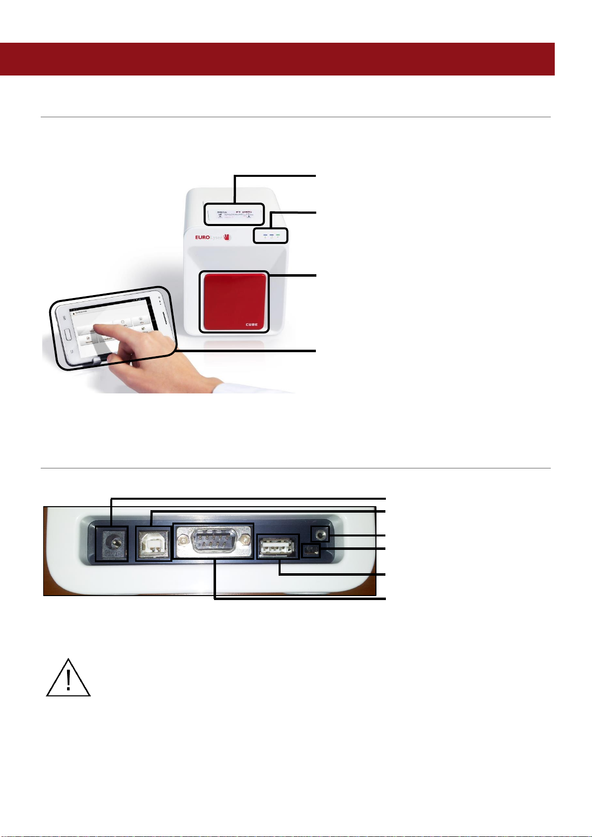
RFID Card Pit The RFID card is placed
here
Indicator Lights There are 3 LEDs on the
front of the Instrument.
For a detailed description
refer to page 10
Door Test cartridges are inserted
and then removed here.
Note: do not attempt to open
door manually!
Tablet PC The Tablet PC is the main
user interface to operate the
Instrument & process the
results
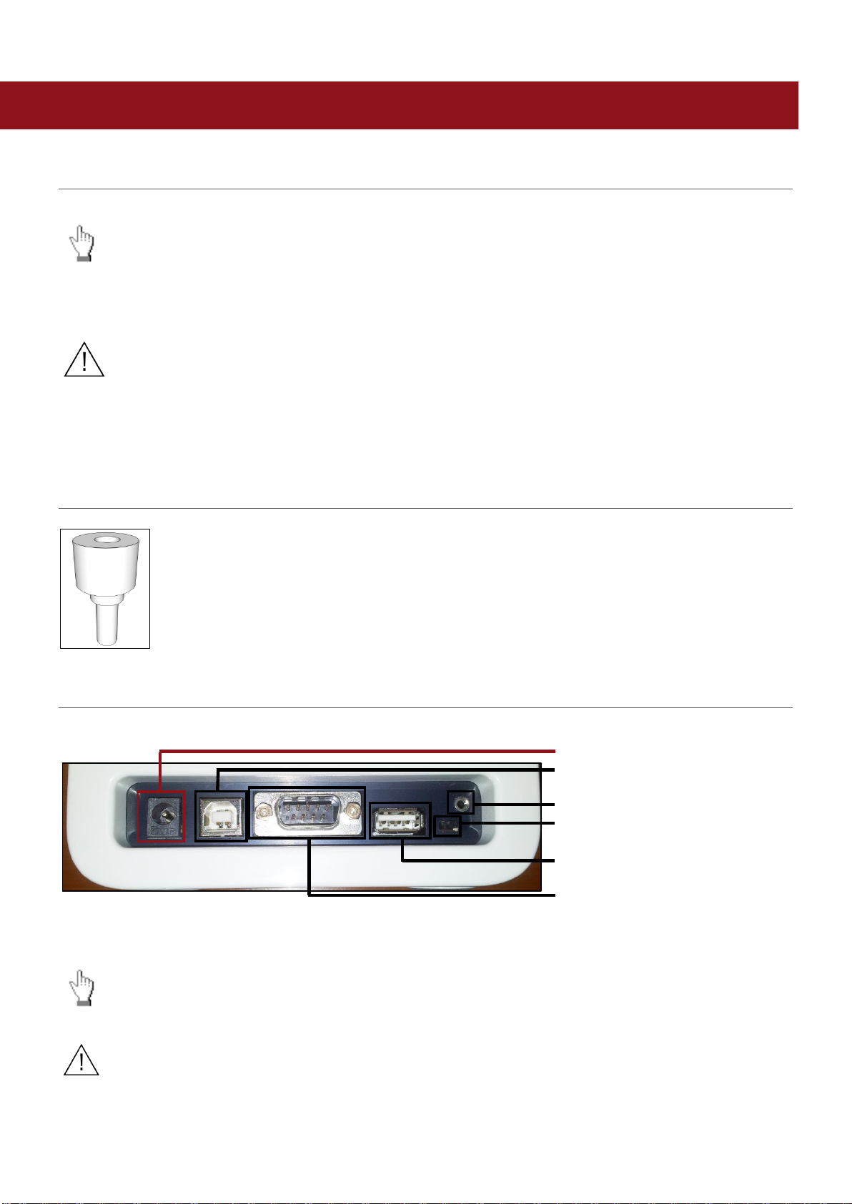
CUBE-S/CUBE Instrument Interfaces
.Eurolyser CUBE-S/CUBE Instrument Interfaces
Power supply
USB Socket for connecting a
PC (for data transfer)
Tablet PC-Lock eyelet
Bluetooth on/off switch
(left: Bluetooth OFF)
USB Port for connecting a
Tablet PC
RS 232 socket for connecting a
printer, a barcode reader or a
PC (for data transfer)
Do not use liquid cleaners on the Instrument or Tablet PC! Use a lint-free,
slightly damp cloth only!
Do not attempt to open the door manually
2ad89664-e5f4-4907-bab1-9f7c76e7d9ef / DP10.0 / 2016-07-04 Page 10 of 43 Eurolyser Diagnostica GmbH
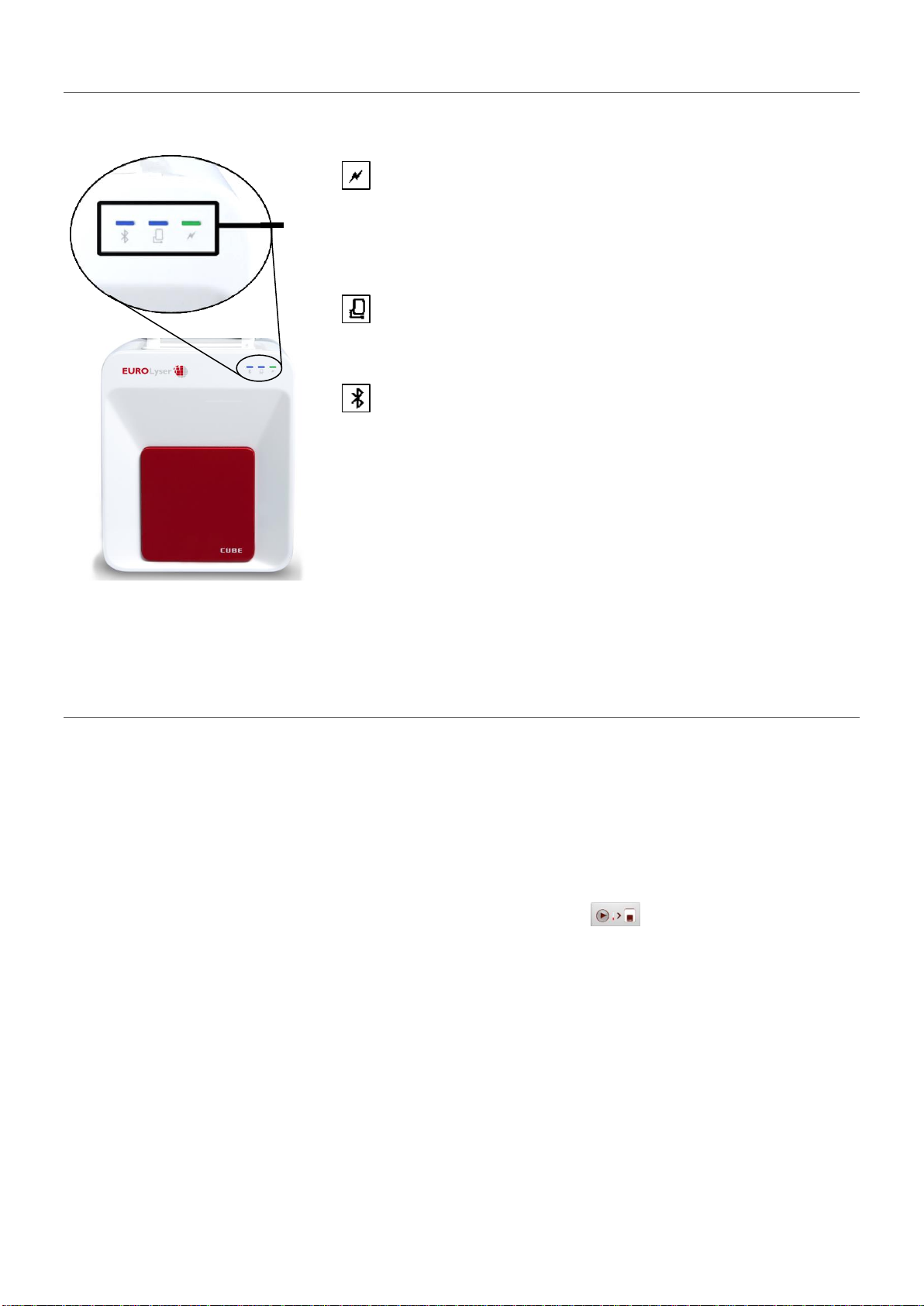
LEDs
Indicator lights
Eurolyser CUBE-S/CUBE front
LEDs on the Eurolyser CUBE-S/CUBE Instrument
This green LED indicates the readiness of the photometer
Flashing: the Instrument is warming up and testing cannot be
started yet (Note: this takes approximately 10 min.)
Constantly lit: the Instrument is warmed up and ready for use
Off: the Instrument is not plugged in
This blue LED indicates a connection to a Tablet PC
Constantly lit: a connection with a Tablet PC is established
Off: the Tablet PC is not connected
This blue LED indicates a Bluetooth connection to Tablet PC
Constantly lit: a connection with a Tablet PC is established
Flashing: Bluetooth is activated on the photometer but no
Tablet PC is connected via Bluetooth
Off: Bluetooth is switched off
Note: The Bluetooth connection is operational with Tablet PCs
with serial numbers Tb##### or higher. To keep the Tablet PC
constantly powered it is recommended to use the USB cable
connection.
How to handle the Eurolyser CUBE-S/CUBE Laboratory Photometer
The CUBE-S/CUBE Instrument is operated solely by means of the Tablet PC. All the basic operating
steps are displayed as symbols. An overview of these symbols can be found in Table 1 (p. 3) and Table
2 (p. 12). To activate a symbol tap it with a finger.
In order to perform a test, the RFID card enclosed in the test kit must first be placed on the Instrument.
This card contains all the data needed to perform the tests. No analysis can be started without the RFID
test card!
The door opens automatically once a test is initiated by pressing the button. After entering all the
requested data on the Tablet PC and inserting the ERS cartridge into the slot, close the door and the
testing procedure begins automatically. After the analysis is completed, the door opens automatically
and the test cartridge is to be removed.
The door prevents ambient light, dust, dirt and humidity from entering the Instrument during the testing
process and when the Instrument is not in use.
Please make sure the door is closed whenever the Instrument is not in use.

2ad89664-e5f4-4907-bab1-9f7c76e7d9ef / DP10.0 / 2016-07-04 Page 11 of 43 Eurolyser Diagnostica GmbH
How the Eurolyser CUBE-S/CUBE Laboratory Photometer works
The Eurolyser CUBE-S/CUBE Instrument is an open measuring system. This means that it is able to use
various reagents from multiple manufacturers. To perform a test the CUBE-S/CUBE Instrument is loaded
with an ERS cartridge filled with reagents from the respective reagent manufacturers. The Instrument
can process endpoint tests, kinetic tests and coagulation tests. Due to the latest LED technology used it
is maintenance-free.
The Instrument is equipped with an RFID card-reader module. RFID cards are necessary for performing
any testing procedures. They are included in the test kits from the respective test manufacturers and
contain all the specific steps for the various tests, the lot data, as well as the calibration data. The
Instrument performs the tests automatically according to that data. Numerous types of tests can be
selected and performed automatically.
The sample and the reagent are automatically mixed within the Instrument. The photometer unit
performs the analysis with a light diode. The absorption of light rays is measured during this process and
the measured value is then converted into the test result using mathematical methods. The result is
displayed on the Tablet PC. Optionally, results can be exported to an external computer or an HIS/LIS
and can also be printed out using an external printer.
After the test process the door opens automatically and the ERS cartridge can be removed and
discarded. After confirming the result on the Tablet PC and closing the door on the insturment the
system is ready to perform the next analysis.
Manufacturer calibration
The Eurolyser CUBE-S/CUBE Instrument is manufactured according to the highest quality standards in
order to yield safe and accurate testing results. Every Instrument is inspected and calibrated during the
manufacturing process, using the EU-stipulated reference methods.
2ad89664-e5f4-4907-bab1-9f7c76e7d9ef / DP10.0 / 2016-07-04 Page 12 of 43 Eurolyser Diagnostica GmbH
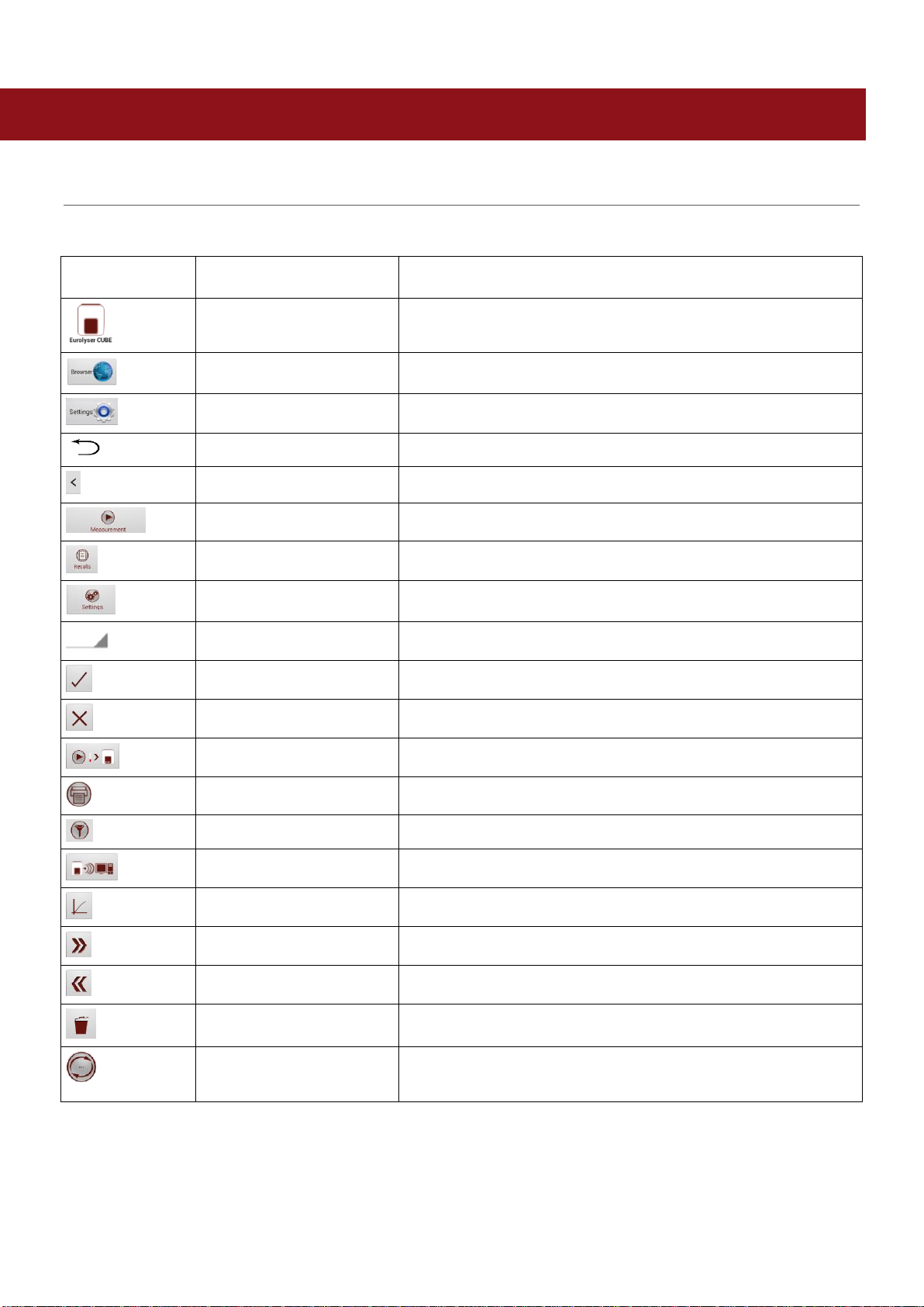
PICTOGRAMMS / BUTTON SYMBOLS
Tablet PC symbols and their functions
Tapping one of these symbols on the Tablet PC activates the described function.
Symbol
Name
Function
CUBE-S/CUBE App Icon
Starts the Eurolyser CUBE-S/CUBE app
Browser
Opens the Web Browser on the Tablet PC
Android Settings
Opens the Android settings menu
Return arrow
Cancels an input OR return to the previous screen or menu
Return to main menu
Returns directly to the main menu
Measurement
Opens the menu for test data entries
Results
Opens the result list screen
CUBE-S/CUBE Settings
Opens the Configuration menu
Edit
Opens an entry or value so it can be edited
Confirm
Confirms the input
Abort to main menu
Cancels an action and returns to the main menu
Start analysis
Starts the test process
Print
Opens the print / export / mail dialogue
Filter
Opens the Filter Options
Transmit
Opens the Export dialogue
Chart
Displays the photometric data curve of a test result
Page forward
Displays the next page
Page backward
Displays the previous page
Recycle bin
Opens the delete dialogue
Synchronize
Synchronises result(s) and Instrument status with the
Eurolyser servers
Table 2: CUBE-S/CUBE Tablet PC symbols
2ad89664-e5f4-4907-bab1-9f7c76e7d9ef / DP10.0 / 2016-07-04 Page 13 of 43 Eurolyser Diagnostica GmbH
GETTING STARTED
The proper placement of the CUBE-S/CUBE Laboratory Photometer
Place the Instrument on a dry, clean, stable and level surface. Make sure the Instrument has at
least 10 cm of table surface and clearance on each side and that the Instrument can be easily
disconnected from the power source. Allow the Instrument to acclimate to the ambient room
temperature before operating it.
The Instrument can be damaged by:
Condensing humidity and water
Heat and large temperature fluctuations
Direct sunlight
Vibrations (e.g. from centrifuges and dishwashers)
Electromagnetic radiation
Electrostatic discharge
Transport lock
Upon first use the white transport lock is to be removed from the door of the Instrument.
Note: keep both the transport lock and the original packaging. In case of a defect the
Instrument is to be returned in the original packaging (see p. 8) with the transport lock
installed to prevent any damage during transportation!
Connecting the power supply
.Eurolyser CUBE-S/CUBE Instrument Interfaces
Power supply
USB Socket for connecting a
PC (for data transfer)
Tablet PC-Lock eyelet
Bluetooth on/off switch
(left: Bluetooth OFF)
USB Port for connecting a
Tablet PC
RS 232 socket for connecting a
printer, a barcode reader or a
PC (for data transfer)
-Connect the power cable to the power supply unit.
-Insert the plug from the power supply unit into the power socket on the back of the Instrument
-Plug the power cable into the wall socket.
Always connect to the proper supply voltage. The power supply voltage must comply
with the regulations cited in the technical specifications on page 40. Ensure a properly
installed electrical grounding. The Instrument is to be operated only using the power
supply unit provided.
2ad89664-e5f4-4907-bab1-9f7c76e7d9ef / DP10.0 / 2016-07-04 Page 14 of 43 Eurolyser Diagnostica GmbH
The Tablet PC
The Eurolyser CUBE-S/CUBE Instrument is operated with a Tablet PC.
Connect the Tablet PC to the USB port of the plugged-in Instrument and then turn on the Tablet PC.
An independent Tablet PC manual is delivered with the Tablet PC. It describes in detail the operating of
the Tablet PC, how to manage settings and the establishing of a Bluetooth or USB connection between
the CUBE-S/CUBE and the Tablet PC.
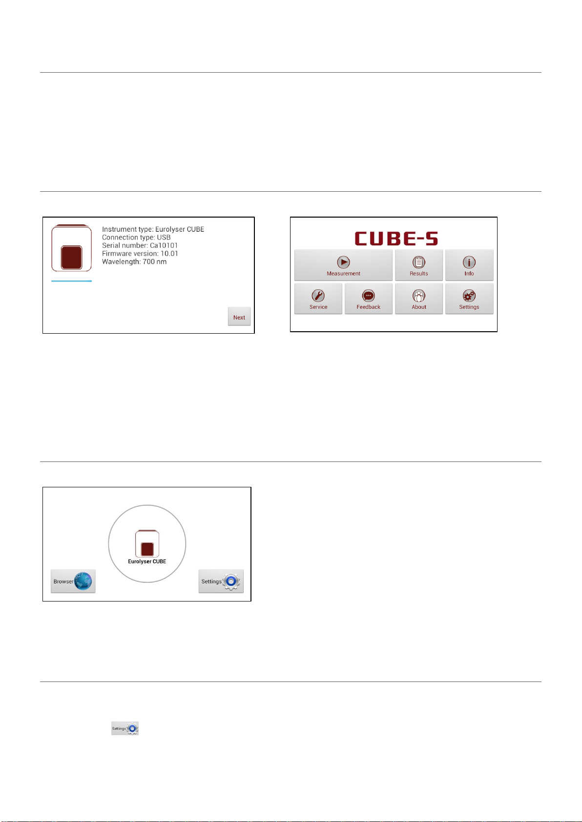
Starting & Operating the Tablet PC
1. Connection Screen
2. Main Menu
The connection screen appears upon connecting
the Tablet PC with the CUBE-S/CUBE
Instrument.
Tap Next to continue.
The CUBE-S/CUBE app starts and the main menu
appears.
Note: while the Eurolyser CUBE-S/CUBE
Instrument is warming up (indicated by the flashing
green LED on the front) the “Measurement” Button
is grey and inactive.
The Eurolyser CUBE-S/CUBE Launcher
Eurolyser CUBE-S/CUBE Launcher
When the Tablet PC is not connected to the
Instrument or by pressing the Home Button the
Eurolyser CUBE-S/CUBE Launcher appears:
Tapping Browser opens the Android web browser
Tapping Eurolyser CUBE-S/CUBE starts the CUBE-
S/CUBE app
Tapping Settings opens the Android settings menu
Note: If the standard Android Desktop appears
instead, switch the Tablet PC off, back on, select
“CUBE-S/CUBE Launcher” and confirm by tapping
“Always”.
Changing the language of the Eurolyser CUBE-S/CUBE application
The language of the application is automatically set according to the language of the operating system of
the Tablet. It can be changed by pressing the home button on the Tablet PC (the launcher appears),
then pressing to open the settings. Swipe down and select Language and input in the category
“Personal”. Tap Language and choose a language. Press the home button to return to the launcher.

2ad89664-e5f4-4907-bab1-9f7c76e7d9ef / DP10.0 / 2016-07-04 Page 15 of 43 Eurolyser Diagnostica GmbH
Note: the Eurolyser CUBE-S/CUBE application supports several languages. If you choose a language in
the system settings that is not supported by the CUBE-S/CUBE app English will be used.
How to switch the Eurolyser CUBE-S/CUBE Laboratory Photometer ON
The Instrument is switched on by plugging the power cable into the socket. This launches the
Instrument’s automatic start-up and warm-up processes. Please wait for these to be completed
(approximately 10 minutes).
When operating the Instrument:
The door protects the analysis system from dust, dirt and humidity. Empty the
door’s cartridge chamber after every analysis and keep it closed when the
Instrument is not in use.
The door opens automatically. Do not attempt to open the door manually!
If an error message appears during an analysis, please consult the
“Troubleshooting” section on page 38.
The automatic start-up and warm-up processes
1. Warm-up menu
2. Main Menu
The automatic start-up procedure (indicated by the flashing green LED) starts as soon as the Instrument
is connected to the power supply. The Instrument is warmed up to its proper working temperature in
approximately 10-15 minutes.
As soon as the initialization of the optical unit is completed, the button turns from b/w to color and
reacts to tapping. The Instrument is now operational.
2ad89664-e5f4-4907-bab1-9f7c76e7d9ef / DP10.0 / 2016-07-04 Page 16 of 43 Eurolyser Diagnostica GmbH
CONFIGURING THE EUROLYSER CUBE-S/CUBE
You can configure your Eurolyser CUBE-S/CUBE laboratory photometer according to your needs before
using it. To access the configuration menu follow these steps:
1. Start-up menu
2. Settings menu
Tap to open the Settings
menu.
Tap the setting you want to
configure. Swipe down to view all
available options.
All following descriptions are examples. The configuration of the Eurolyser CUBE-S/CUBE
Instrument models may vary depending on the tests used.
Note: The normal values, units and sample types for a test can only be displayed if the
respective test RFID card has been placed on the Instrument and read.
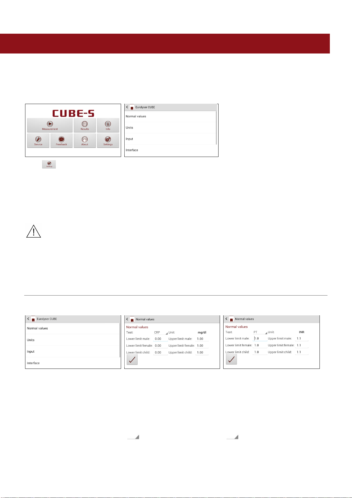
Setting normal values and limits
1. Settings menu
2. Normal values/limits menu, e.g. CRP
2.1 Normal values/limits menu, e.g. PT
Tap Normal Values to open the
Normal Values / Limits menu.
To change a limit tap the value
and change it using the appearing
Tablet PC keyboard.
To change the test for which the
normal values are displayed tap
and select a test in the
appearing drop down menu*.
To change a limit tap the value
and change it using the appearing
Tablet PC keyboard.
To change the test for which the
normal values are displayed tap
and select a test in the
appearing drop down menu.

2ad89664-e5f4-4907-bab1-9f7c76e7d9ef / DP10.0 / 2016-07-04 Page 17 of 43 Eurolyser Diagnostica GmbH
Setting units
1. Configuration menu
2. Unit selection menu
Tap Units to open the Unit
selection menu.
Tap and select a unit in the
appearing drop-down menu.
Confirm the change(s) with .
Configuring inputs (Sex, Sampletype, Hematocrit, Operator)
1. Configuration menu
2. Input menu
3.1 Default sex menu
Tap Input to open the input menu.
Tap a parameter and the
respective menu will open.
The following descriptions are
provided in the order of the
parameters in the Input menu.
Tapping opens a drop down
menu. Select which gender is to
be used as the standard default.
Last used means that the gender
last used will always be selected.
3.2 Sampletype menu
3.3a Hematocrit menu (CUBE Analyser)
3.3b Hematocrit menu (CUBE-S Analyser)
Tap and a drop down menu
opens, select which type of
sample should be selected by
default. Last used means the
sample type last used will be
selected. Confirm with .
Press to cancel.
Tap a desired hematocrit value
and change it using the
appearing Tablet PC keyboard.
Confirm the change(s) with .
Press to cancel.
Choose HCT Auto for an analyser-
side calculation of the HCT value or
HCT Manual for defining your own
HCT values. Tap a desired
hematocrit value and change it
using the appearing Tablet PC
keyboard. Confirm the change(s)
with . Press to cancel.

2ad89664-e5f4-4907-bab1-9f7c76e7d9ef / DP10.0 / 2016-07-04 Page 18 of 43 Eurolyser Diagnostica GmbH
3.4 Operator menu
Enable the operator mode by
tapping the button.
To create a new operator, type the
name in the box and then tap .
To delete an operator, tap
and select a name in the drop
down menu, then tap .
Configuring interfaces
1. Configuration menu
2. Interface menu
3.1 Printer configuration menu
Tap Interface in the Configuration
menu. The Interface menu
appears.
Tap an interface to configure and
the respective configuration menu
appears.
The following descriptions are in
the order of the interfaces in the
Interface menu.
Tap a checkbox next to an option
to select or de-select it.
Note: the screenshot above is for
demonstration purposes only. By
default all boxes are unchecked.

2ad89664-e5f4-4907-bab1-9f7c76e7d9ef / DP10.0 / 2016-07-04 Page 19 of 43 Eurolyser Diagnostica GmbH
3.2a Host configuration password screen
3.2b Host configuration menu
The service password is required
to change interface host options.
Tapping on the input field opens
the Tablet PC keyboard and the
password can be typed. After
pressing OK on the password
screen, the host configuration
menu opens.
If you do not know the Service
Password please contact your
dealer.
Tap a checkbox next to an option
to select or de-select it. Checking
Automatic transmission allows for
automatic transmission of the
standard information of a
measurement result after the
measurement is done via USB or
serial port. Operator ID, lot
number and serial number are
additional information that can be
added to the Automatic
transmission or standard manual
transmission format.
Note: the screenshot above is for
demonstration purposes only. By
default all boxes are unchecked.

2ad89664-e5f4-4907-bab1-9f7c76e7d9ef / DP10.0 / 2016-07-04 Page 20 of 43 Eurolyser Diagnostica GmbH
OPTIONAL EQUIPMENT
Printer, barcode scanner or PC
The following optional devices (not included in the standard delivery package) can be connected to the
Instrument:
An external printer –for optional test result printouts
An external barcode scanner
A PC –for the transfer of test data into a HIS or laboratory software
To install the printer (see “Technical specifications” section on page 40)please connect the RS232 cable
to the RS232 socket at the Instrument.
Connect optional equipment only when the Instrument is switched off. Please note
that attaching optional equipment (e.g. a printer) can increase the amount of
leakage current. All optional equipment must be connected before such leakage
current can be measured.
If the Instrument is not used according to the instruction manual, then the provided
levels of safety will be lowered.
Connecting a barcode scanner
To install the barcode reader (see “Technical specifications” section on page 40) please connect the
RS232 cable to the RS232 socket at the Instrument (see illustration below). Always connect the power
supply to the barcode scanner correctly before using it.
If a printer should be installed simultaneously an adapter has to be interconnected (e.g. barcode-printer-
interface-cable, Eurolyser order number: SZ0405).
.Eurolyser CUBE-S/CUBE Instrument Interfaces
Power supply
USB Socket for connecting a
PC (for data transfer)
Tablet PC-Lock eyelet
Bluetooth on/off switch
(left: Bluetooth OFF)
USB Port for connecting a
Tablet PC
RS 232 socket for connecting a
printer, a barcode reader or a
PC (for data transfer)
This manual suits for next models
1
Table of contents
Popular Laboratory Equipment manuals by other brands

Energenics
Energenics UV-MAX Installation & operation manual

Pasco Scientific
Pasco Scientific ME-6956 Instruction manual and experiment guide

Thermoline Scientific
Thermoline Scientific TU-1 operating instructions

Leica
Leica RM2255 Instructions for use

Buchi
Buchi NIRMaster Supplement Installation Manual

Cannon
Cannon CT-1000 manual


