WPI MPS-4 User manual

WORLD
PRECISION
INSTRUMENTS
MPS-4
Multichannel Perfusion System
Serial No._____________________
www.wpiinc.com
INSTRUCTION MANUAL
011720


MPS-4
World Precision Instruments i
Copyright © 2020 by World Precision Instruments. All rights reserved. No part of this publication may
be reproduced or translated into any language, in any form, without prior written permission of World
Precision Instruments, Inc.
CONTENTS
ABOUT THIS MANUAL ................................................................................................................... 1
INTRODUCTION .............................................................................................................................. 1
Notes and Warnings................................................................................................................. 2
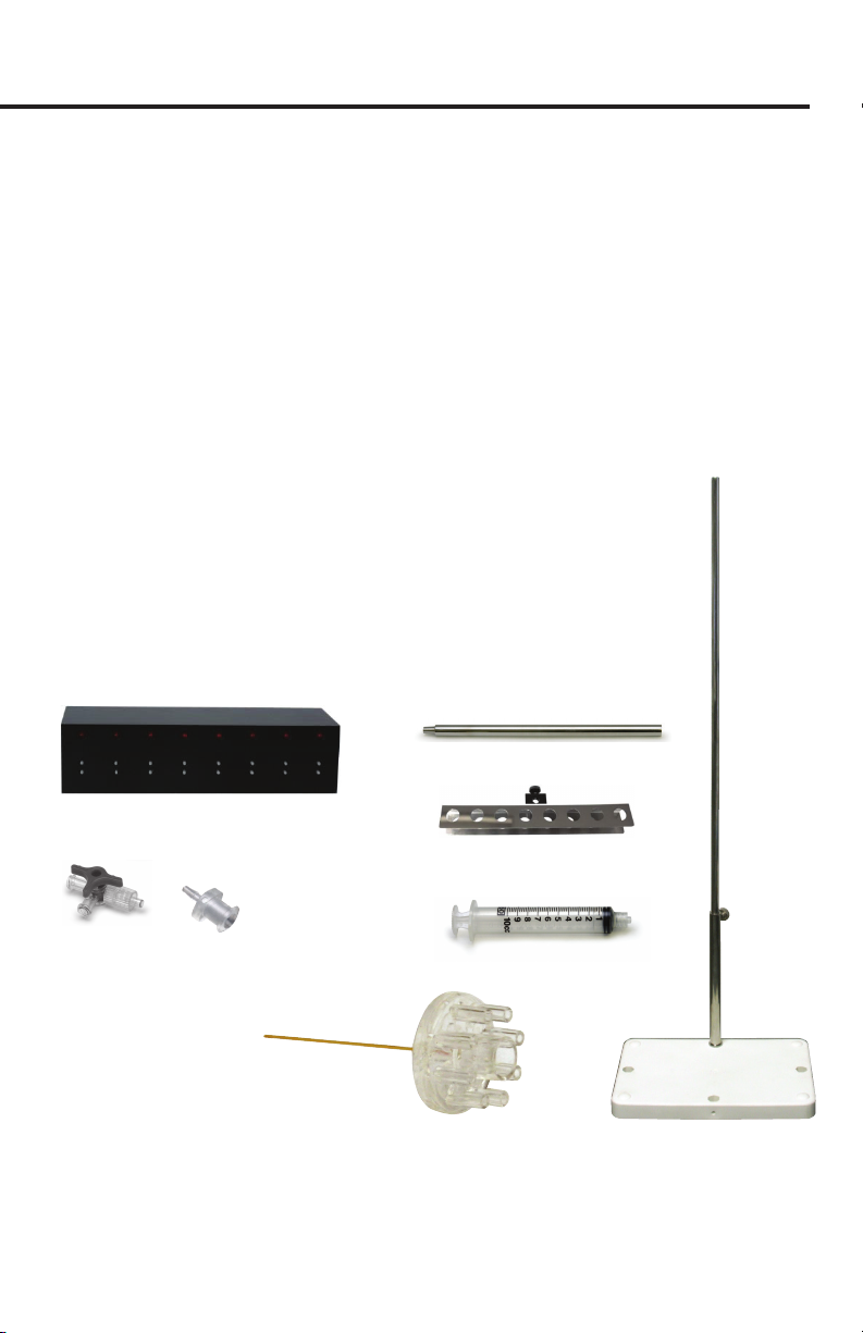
Parts List...................................................................................................................................... 3
Unpacking................................................................................................................................... 4
INSTRUMENT DESCRIPTION ........................................................................................................ 4
Hardware Installation............................................................................................................... 4
OPERATING INSTRUCTIONS......................................................................................................... 5
Software Installation................................................................................................................. 6
Installation............................................................................................................................. 6
Startup ................................................................................................................................... 6
Creating a New Perfusion Experiment ................................................................................ 6
Set the Experiment Time......................................................................................................... 7
Preset Each Channel’s Perfusion Time ................................................................................ 7
Saving Your Experimental Parameters................................................................................ 9
Mode Selection .................................................................................................................... 9
Computer Perfusion Control Modes............................................................................10
Run Perfusion.....................................................................................................................10
Hardware Testing Procedure...............................................................................................11
Testing Drug Delivery.............................................................................................................12
MAINTENANCE ..............................................................................................................................13
Cleaning.....................................................................................................................................13
TROUBLESHOOTING ...................................................................................................................13
APPENDIX A: DETERMINING FLOW RATE................................................................................14
Theoretical Calculation ..........................................................................................................14
APPENDIX B: DISABLE DRIVER SIGNATURE ENFORCEMENT (WIN10) .............................15
APPENDIX C: HOW TO INSTALL AN UNSIGNED DRIVER ON WINDOWS 8 ..................... 19
APPENDIX D: INSTALL THE MPS-4 SOFTWARE ON WINDOWS 10....................................22
WARRANTY .....................................................................................................................................31
Claims and Returns ................................................................................................................31
Repairs.......................................................................................................................................31

ii World Precision Instruments

MPS-4
World Precision Instruments 1
ABOUT THIS MANUAL
The following symbols are used in this guide:
This symbol indicates a CAUTION. Cautions warn against actions that can cause
damage to equipment. Please read these carefully.
This symbol indicates a WARNING. Warnings alert you to actions that can cause
personal injury or pose a physical threat. Please read these carefully.
NOTES and TIPS contain helpful information.
Fig. 1—The MPS-4 controller operates the eight channels.
INTRODUCTION
The MPS-4 is a programmable 8-channel perfusion system designed for single
channel and whole-cell patch preparations. It oers the best combination of
performance and value. The improvement of MPS-4 over the previous MPS-2 is
the use of a diaphragm type solenoid valve that completely isolates the perfusion
solution from the outside to avoid the inuence of metal ions in the moving iron of
the solenoid valve on the experimental results. Unlike other perfusion systems on the
market, which often compromise performance to t every possible application, the
MPS-4 is the only perfusion system designed and optimized specically for single-
channel and whole-cell patch perfusion applications.
The system can be controlled manually (i.e., via membrane switches on the front
panel) or through a PC. Two dierent manual control modes are oered. One controls
each channel independently and the other mode allows sets channel 8 as the master
channel that will keep the system owing when all other channels are switched o.
User-friendly timing software is included, and the programmed perfusion sequence
can be started by computer, a TTL trigger from an external source such as a patch
clamp amplier or manually by the user. The high level (ON= +3 ~ +5V) and low level
(OFF = 0 ~ +1V) control mode that permits independent control of each valve by the
external instruments or data acquisition system.

2 World Precision Instruments
The perfusion uid ows through specially designed, color-coded, polyurethane
ribbon style tubing. The color-coding allows you to easily trace each channel for
diagnostic or set up. The ribbon style of the tubing keeps the system neat and clean.
Unlike PVC based tubing, polyurethane tubing contains no plasticizer, which can cause
contamination.
The most unique feature of the MPS-4 is its perfusion µ-manifold. Using the latest
microuidic techniques, the injection molded µ-manifold provides the least ow
resistance and dead volume of any product on the market. The ow channel inner
diameter is approximately 1 mm, except for the last 5 mm before the junction point.
This design allows a fast ow rate without using a pressurized system. The maximum
ow rates are 1 and 16 µL/s for the 15 mm long 100 µm and 250 µm ID tips,
respectively. Small channels and a unique design at the merging point further reduce
the chance of cross contamination. Dead volume is less than 100 nL. The injection-
molded µ-manifold is also designed as an economical disposable item, eliminating
problems of cross-contamination from other experiments.
Notes and Warnings
NOTE: Before starting a formal experiment, perform several preliminary tests, such as
the drug interaction range test, to get familiar with this perfusion system.
NOTE: The 100 and 250 µm perfusion manifold tips are made of ne glass capillary,
which is subject to breakage and clogging. Handle the tip carefully during the
experiment.
CAUTION: Tubing must be removed gently so that the manifold is not
damaged.
CAUTION: Any organic solvent, including alcohol, may damage the perfusion
manifold.
CAUTION: All the drug solutions should be ltered before use to prevent
clogging of the perfusion head.
CAUTION: After the experiment, the tubing system (especially the
electromagnetic valve, manifold and perfusion head) should be thoroughly
washed with warm, fresh distilled water as soon as possible. Failure to do so
may cause damage to the system. See “Cleaning” on page 13.
CAUTION: If the MPS-4 system does not work properly, stop the experiment
immediately. Switch o the power. See “Troubleshooting” on page 13.

MPS-4
World Precision Instruments 3
Parts List
After unpacking, verify that there is no visible damage to the sensor.
Verify that all items are included:
(1) Stand base and Stainless Steel Post
(1) MPS-4 Controller
(1) Valve Console
(1) Syringe Holder
(1) Power Cord
(1) USB Cable
(2) 1A Fuse
(10) 10mL Syringes
(10) 3-way Stopcock
(10) Luer tting with barb for 1/16” ID tubing
(5’) Color Coded Polyurethane Tubing Ribbon
(1) µ-manifold Holding Rod
(1) µ-manifold with 100µm ID tip
(1) µ-manifold with 250µm ID tip
(1) Installation Software
(1) Instruction Manual
Valve Console
Syringe Holder
Stand, post
3-way Stopcock
(#3744-100) 10 mL Syringe
(#3744-100)
Luer Fitting for 1/16” ID
tubing (#13156-100)
µ-Manifold
100µm: #502110
250µm: #502125
Manifold Holder
Fig. 2—These components are included with the MPS-4 system.

4 World Precision Instruments
Unpacking
Upon receipt of this instrument, make a thorough inspection of the contents and
check for possible damage. Missing cartons or obvious damage to cartons should be
noted on the delivery receipt before signing. Concealed damage should be reported
at once to the carrier and an inspection requested. Please read the section entitled
“Claims and Returns” on page 31 of this manual. Please contact WPI Customer
Returns: Do not return any goods to WPI without obtaining prior approval (RMA
# required) and instructions from WPI’s Returns Department. Goods returned
(unauthorized) by collect freight may be refused. If a return shipment is necessary,
use the original container, if possible. If the original container is not available, use a
suitable substitute that is rigid and of adequate size. Wrap the instrument in paper or
plastic surrounded with at least 100mm (four inches) of shock absorbing material. For
further details, please read the section entitled “Claims and Returns” on page 31 of
this manual.
INSTRUMENT DESCRIPTION
Hardware Installation
1. Set the MPS-4 perfusion stand on a stable platform.
2. Insert the stainless steel post into the base and tighten the screw.
3. Loosen the screw on the back of the valve console and x it onto the post. Set
the distance between the valve console center point and top of the post to the
desired height.
4. Fasten the syringe holder onto the post.
5. Connect the valve console to the MPS-4 instrument with the cable supplied.
6. Pull out of the plungers of the syringes and put the syringes into the syringe
holder.
7. Connect the 3-way stopcocks to the syringes.
8. Cut a 20cm long section of the color-coded polyurethane tubing. Split it to 8
individual tubes and put the luer tting to one end. Connect the luer tting to the
3-way stopcock.
9. Connect the other ends of the eight tubes to the inputs of the valve console.
10. Split one end of the long color-coded polyurethane tubing for about 15cm.
Connect the splited end to the valve output port on the valve console.
11. Carefully connect the other ends of the polyurethane tubing to the µ-manifold.
CAUTION: In this step, the manifold should not be connected to the holding
rod. The female luer port may be damaged by the force applied to the manifold
when attaching the 8 ends of the tubing.

MPS-4
World Precision Instruments 5
12. Connect the stainless holder rod to the µ-manifold. The end of the holder rod is
a male luer tting. It can be pressed into the center hole of the µ-manifold for a
secure hold. Fix the holder to a micromanipulator.
TIP: We recommend WPI’s KITE-L for this purpose. It has sucient precision for
the perfusion tip and an economical price. It has a left hand scale for placing on
the left side of the microscope, leaving the right side free for the patch pipette.
13. Connect the MPS-4 to a computer USB port.
14. Connect a cable with a BNC plug to the socket on the back panel of MPS-4
controller corresponding to the channel to be controlled. Connect the other end
of the cable to the equipment that generates the control signal.
OPERATING INSTRUCTIONS
Fig. 3—The front panel of the MPS-4 has the operational controls.
The left section of the MPS-4 front panel contains the Start, Reset and Mode buttons,
and three functional indicator LEDs.
Start button–The button runs the perfusion process. In the Online mode,
it acts as the button and runs the experiment controlled by the
perfusion software. In Oine mode, the Start button runs the preset
perfusion parameters saved to the RAM of the control box from the
computer.
Reset button–This button is the zero button for the micro-controller. It
stops any currently running experiment, turns all channels o and resets
the mode to Manual. Press the button and hold it for 1 second before
lifting it to ensure the system is completely reset.
Mode button–This button toggles the perfusion mode between Manual,
Online, Oine and Master Manual. Once a mode is selected, the
corresponding LED illuminates. In Master Manual mode, the Manual LED
blinks continuously.

6 World Precision Instruments
Fig. 4—The Mode button toggles between the four operational modes.
Software Installation
System Requirements: Windows 7, 8, 8.1 or 10 PC, 10 Mb free hard drive space; CD-
ROM or DVD-ROM driver.
Installation
NOTE: The installer must have administrative privileges on the computer.
For complete instructions, see:
• “Appendix B: Disable driver signature enforcement (Win10)” on page 15
• “Appendix C: How to install an unsigned driver on Windows 8” on page 19
• “Appendix D: Install the MPS-4 software on Windows 10” on page 22.
Startup
The perfusion software can be found in the Start menu of Windows under C:\Program
Files (x86). The software automatically connects to the MPS-4 on startup. If the MPS-4
is plugged into the computer after the program has been loaded, press the button
to establish a connection.
Creating a New Perfusion Experiment
The Experiment menu allows you to open a new or
existing perfusion experiment.
After clicking on “New Experiment”, two new
windows pop up to allow you to set the experimental
parameters.

MPS-4
World Precision Instruments 7
Fig. 5—The View window and the Setup window pop up.
Set the Experiment Time
The rst step in creating a new experiment is to set
the (Total) Experiment Time.
The format is Hours:Minutes:Seconds:Milliseconds. Hold
down the left mouse key over one of these elds to get the
a double arrow ( ) cursor. To adjust the value, move the
mouse up or down. If you double click on a eld, the value
can be entered directly with the keyboard. Move to the next
eld by lling in both digits of the eld or by pressing the
spacebar. Click Apply when all elds are set to the desired
values. The perfusion time shown at the right is set for 2
minutes.
Preset Each Channel’s Perfusion Time
1. Choose the desired channel by clicking on the box in front of the channel name
in the experiment window, or by clicking on the channel number in the Setup
window. In this example, we will be working with the Channel 5.
Fig. 6—Click the box in front of the channel name or the channel # in the setup window.
2. Press the Insert button on the bottom of the Setup window to add a Start

8 World Precision Instruments
Time and Stop Time. Click once on a start time or a stop time to select it. Once
selected, the values of its elds can be set the same way as the Experiment
Time. If the “Time Setup” option in the Mode Setup window (F3) is changed, then
“Duration” is displayed instead of “Stop Time”.
Fig. 7—Set the start and stop times.
4. Press Insert again to add new rows. Once all times are entered for a channel,
click Apply to verify the changes. Otherwise, the new values will be lost when a
dierent channel is chosen or the Setup window closes.
5. You can also set the perfusion time by holding the left mouse key, moving to the
right position and releasing the key. The precise time at the mouse position is
displayed at the right hand side of the status bar at the bottom of the screen.
Fig. 8—Set the perfusion time.
6. After the parameters have been successfully set, the program interface is shown.
Follow the same procedure to nish the rest of the channel programming.
Fig. 9—This View window shows the setup for Channel 5.

MPS-4
World Precision Instruments 9
Saving Your Experimental Parameters
Select Save As from the Experiment menu. A second window pops up. Select the le
name and folder to save the le. You can also use the system default le name, which
is made of 12 digital numbers to indicate the year, month, day, hour, minute and
second. In the window below, the le was saved 8/1/2019 18:32:41.
Fig. 10—Enter a le name in the Save As dialog box.
Mode Selection
In order to change the operation mode or choose the serial port, choose Mode Setup
from the Operation menu, press the F3 function key, or click the button in the
Tool Box. The Mode Setup window pops up. Click on the desired mode and press OK
to activate it.
Fig. 11—Use the Mode Setup window to select a mode.
Manual mode, Online mode, Oine mode and Master Manual mode are settings for
the MPS-4 electronic unit. When a mode is chosen, the appropriate LED illuminates
on its front panel. Master Manual mode makes the Manual LED blink continuously.
The Time Setup option toggles the time entry mode of the Setup window from Start
Time/End Time to Start Time/Duration.

10 World Precision Instruments
Manual mode
Online mode
Offline mode
Master manual mode
Download mode
The modes can also be viewed and selected with the following icons located on the
toolbar. From left to right, these icons represent Manual mode, Online mode, Oine
mode, Master Manual mode and Download mode.
Computer Perfusion Control Modes
Online Mode–In this mode, perfusion is controlled by the computer software in real
time. Run, Pause and Stop can be controlled from the Operation menu, the toolbar
icons , or with the function keys (F8, F9 and F10 as shown on the Operation
menu).
Data Download Mode–The experimental procedure created with the software is
downloaded into the RAM of the MPS-4 control box when you press the button or
select Download from the Operation menu. The Online LED on the MPS-4 control
box blinks while the program is being transferred.
MPS-4 Controller Operation–The left section of the MPS-4 front panel contains the
Start, Reset and Mode buttons, and three functional indicator LEDs:
• Start button–The button runs the perfusion process. In the Online mode, it acts
as the button and runs the experiment controlled by the perfusion software.
In Oine mode, the Start button runs the preset perfusion parameters saved to
the RAM of the control box from the computer.
• Reset button is the zero button for the micro-controller. It stops any currently
running experiment, turns all channels o and reset the mode to Manual.
• Mode button toggle the perfusion mode between Manual, Online, Oine and
Master Manual. Once a mode is selected, the corresponding LED illuminates. In
Master Manual mode, the Manual LED blinks continuously. The operation of each
mode is described in the following sections.
Run Perfusion
Normal Mode–In this mode, the 8 channels are independently controlled by pressing
the channel buttons. When a channel is on, its LED lights up.
Master Channel Mode–This is just like the normal Manual mode except that only
one channel can be on at a time. If all other channels are turned o, channel 8 (the
master channel) automatically turns on. When this mode is rst selected, it is in the
inactive state in which all channels are turned o. Press the channel 8 button to toggle
between the active and inactive state.

MPS-4
World Precision Instruments 11
On-line Perfusion Mode–This is the computer software controlled mode. There are
three ways to run the perfusion experiment:
• Click the (Run) button in the software
• Press the Start button on the front panel
• Use the external triggered TTL input.
While an experiment is running from the computer, channels can also be turned on
and o by pressing the channel buttons on the front panel.
O-line Perfusion Mode –In this mode, the you can use Start button or externally
triggered TTL input signal to start the perfusion program and perform the perfusion
according to the preset parameters saved in the control unit’s RAM from the
computer. Note that there is a delay of about 25 ms while the stored sequence is
initialized. Perfusion cannot be independently controlled with the channel buttons in
this mode.
TTL Control Mode–Each channel is independently controlled by its own input voltage
from the BNC socket on the back panel. The MPS-4 automatically goes into this mode
when any one of the control inputs goes high (+3~5 V) and this channel will open.
Then it will close when the input voltage of this socket is low (0~+1 V). While this mode
remains active, the Oine LED blinks continuously. The Mode button is disabled, but
Reset can still be used to close all open valves and return to Manual mode. Press
any of the Channel keys if the experiment has to be manually halted. This will exit
out of TTL Control mode and prevent it from going back into that mode until Reset is
pressed or the instrument is turned o and on.
Hardware Testing Procedure
In order to make sure the perfusion system works perfectly, the connection of the
tubing to all of the valves and connectors should be sealed tightly without any leakage
of the air pressure. In addition, there should not be any air bubbles present inside
the output of the tubes. Since the inner diameter of the tubing is so small, any air
bubble inside the tubing can cause the ow of solution to stop due to blockage by air.
Therefore, before the experiment, use the following procedure (commonly referred to
as priming) to check for air leakage and remove the bubbles in the tubing.
1. Fill all the syringes with the distilled water and open the 3-way stopcock. Check if
there is any water leakage. Fix any leakage.
2. Turn on the power.
3. Turn on the rst channel switch, until water droplets come out from the
µ-manifold tip.
4. During step 3, air bubbles might prevent the water droplets from coming out of
the tubing. To clear all air from the system, attach a syringe lled with distilled
water to the side port of the stopcock. Turn the stopcock knob so that the syringe
on the upper port is disconnected and push the air out with the side port syringe.
Repeat steps 3 and 4 for channels 2 to 8.
5. Carefully install the µ-manifold. Turn on and o the channel switches for channel

12 World Precision Instruments
1 to 8 in sequence, until the water droplets of each channel comes out of the
micro perfusion head continuously.
6. Determine the ow velocity at the micro perfusion head from each channel
using a stopwatch. Flow velocity for dierent channels should be about the
same. Otherwise, check for air leakage or residual bubbles in the corresponding
channel.
Testing Drug Delivery
The drug perfusion area of the MPS-4 series can cover the whole view eld of
a 200X microscope (objective 20X, eyepiece 10X). However, in order to perform
the experiments in an eective and reliable way, we suggest several preliminary
experiments as a control result. The following procedure uses patch clamp as an
example.
1. Clean the tubing system with distilled water. “Cleaning” on page 13.
2. Fill channel 1 with 150mM ltered NaCl solution. Fill the other channels with
distilled water. Check the system (bubble and ow velocity) as previously
described in “Hardware Testing Procedure” on page 11.
3. Fill the culture dish with NaCl solution, and place it on the microscope stage
4. Adjust the position of the perfusion head using the micromanipulator, so that
the tip of the micro perfusion head is close to the bottom of the dish. The access
angle is about 35-45°.
5. Pull a 1µm micropipette. Fill the pipette with 150mM NaCl solution to make it
a microelectrode, and connect it to a patch clamp amplier. Use the electrode
micromanipulator to position the tip of the electrode right in front of the
perfusion head at the bottom of the glass dish.
6. Apply a 5–10mV voltage between the microelectrode and reference electrode,
and an electric current can be observed passing the electrode. Turning on any
of the distilled water lled channels should cause a rapid decrease of electric
current to zero. Turning o the distilled water and turning on channel 1 brings the
electric current back up to its original level. Test the rest of the channels and the
results should be the same.
7. If the electrode current does not reduce to zero, adjust the position and direction
of the perfusion head and electrode, and repeat step 6. After several tests, you
will get an idea about the right position and direction of the perfusion head, cell
and electrode.
8. After the test, clean the entire tubing system.
9. For a formal experiment, the drug perfusion procedures are almost the same as
above, except that the NaCl solution is replaced by drug solutions, and only the
optimal positions for perfusion head, cell and electrodes are used.

MPS-4
World Precision Instruments 13
MAINTENANCE
Cleaning
Clean the tubing system before and after each experiment. Although the solution path
of the solenoid valve in MPS-4 does not contact with any metal parts, but the drugs
remaining in the solenoid valve will aect the accuracy of subsequent experiments.
So at the end of each experiment, the valve needs to be ushed with distilled water.
Drain the water out afterwards. The protocols for cleaning are as follows:
1. Remove the perfusion µ-manifold from the holding rod.
2. Carefully remove each of the 8 pieces of tubing from the adaptors on the back
of the manifold. It is best to push them from their ends since pulling them o
may damage the perfusion manifold. Pressurizing the tubing may facilitate this
procedure.
3. Turn on the control switches and discharge the drug solutions from all 8 tubing
channels.
4. Keeping the switches open, ll each syringe with warm, distilled water to wash the
tubing and valves. Repeat this step 2 to 3 times.
5. After the manifold is removed from the tubing (step 2), press the provided
cleaning adaptor onto the manifold from the tip end. Connect it to a syringe lled
with ltered water and ush it.
CAUTION: Unltered water could clog the manifold and permanently damage
it. The manifold is made of PMMA material. It can only be washed with water.
Any organic solvent, even alcohol, can permanently damage it. If alcohol must
be used, only use ethyl alcohol.
TROUBLESHOOTING
If there is no perfusion, check the following to locate the problem:
1. You can tell if the perfusion controller is running a perfusion sequence by looking
at the lights above the numbered manual control buttons. When a valve is being
opened, the corresponding light should turn on. If the perfusion controller won’t
turn on at all, check the power cord and the fuse in the back panel. If there is
trouble communicating with the computer in Online mode, make sure the serial
cable is tight and try restarting both the instrument and the PC software.
2. The lights above each channel of the valve console turn on when the valve is
opened. In addition, there a soft click when a valve is turned on or o. If the valve
console is not responding, tighten the cable that connects it to the perfusion
controller.
3. Make sure the stopcock is in the correct position. The middle protrusion on the
knob should be facing away from the syringe uid port on the side.
4. Visually check for air bubbles or obstructions in any segments of tubing. Test
the µ-manifold by connecting a syringe directly to one of its input passages

14 World Precision Instruments
with a piece of tubing. If water ows through the µ-manifold and valve console
separately, try raising the syringe holder or shortening the manifold output
tubing.
5. The MPS-4 system is designed to work with aqueous solutions. Fluids that are
more viscous than water might not ow through the µ-manifold.
NOTE: If you have a problem/issue with that falls outside the denitions of this
troubleshooting section, contact the WPI Technical Support team at 941.371.1003 or
SPECIFICATIONS
This unit conforms to the following specications:
Base......................................................................................................... White plastic over metal
Number of Perfusion Channels...................................................................................................8
I.D. of Micro-perfusion Head Tubing....................................... MP-1 100 µm; MP-4 250 µm
Dead Volume for Perfusion Head..................................................................................<100 nL
TTL Triggering Inputs..................................................................High: +3 ~ 5 V; Low: 0 ~ +1 V
Channels Control Level..................................................................ON: +3 ~ 5 V; OFF: 0 ~ +1 V
Maximum Flow Rates (gravity fed) ................................ 100 µm ID tip, 8 µL/min. at 50 cm
............................................................................................250 µm ID tip, 500 µL/min. at 50 cm
Packing Weight.........................................................................................................................<8 kg
Packing Volume ...............................................................................................680x210x170 mm
APPENDIX A: DETERMINING FLOW RATE
Theoretical Calculation
The relationship of ow rate to the height of the liquid column and inner diameter of
the capillary tubing can be accurately predicted with the Hagen-Poiseuille equation.
F = C (d4PV/L)
F = ow rate in µL/min
P = pressure in mmH2O
L = length of capillary tubing in mm
V = viscosity of the perfusion media in cps
d = diameter of the capillary tubing in micrometers (µm)
C = constant (1.3765 x10⁻⁸).
In most biological systems, the uid has approximately the same density as pure
water, so P is equal to the height of the liquid column in mm. The viscosity of most
biological perfusion solutions can be considered as one. Since the ow is proportional
to the fourth power of the tubing diameter, the restriction of the plastic tubing to
the ow can be ignored. We only need to consider the diameters and lengths of
the quartz tubing, and the uid passages leading up to the 8 to 1 junction. A good
approximation of the resistance of the junction can be obtained by removing the
tubing from one of the 8 manifold inputs, and turning on one of the other channels.
Take the calculated ow resistance and divide it by two.

MPS-4
World Precision Instruments 15
APPENDIX B: DISABLE DRIVER SIGNATURE
ENFORCEMENT (WIN10)
Since we are using legacy drivers and have not yet gotten the driver signature for
Windows 10, you must disable driver signature enforcement temporarily before
installing the 64 bit driver. Please follow those steps below.
1. Since you need to restart the computer multiple times during the operation, you
need to save your unnished work and exit all applications before the disable
driver signature enforcement.
2. Click the Start in the lower left corner of the Windows10 screen, and click the
Settings (gear pattern) in the Start window.
Fig. 12—Click the start button and select the gear icon.
The following window pops up.
Fig. 13—Click the Update & security icon.

16 World Precision Instruments
3. Click the option Update & security and a new window appears.
Fig. 14—Select the Recovery tab.
4. After selecting the Recovery tab, the Advanced startup area appears on the right
side of the window.
Fig. 15—Click Restart now.
Table of contents
Other WPI Laboratory Equipment manuals
Popular Laboratory Equipment manuals by other brands

Thermo Electron
Thermo Electron 3940 Series Operating and maintenance manual

Bertin Technologies
Bertin Technologies Coriolis m user manual

Millipore
Millipore Milli-Q Advantage A10 user manual

MITS
MITS Eleven Auto FPZ-31AT Command manual

Faraday
Faraday DOS-100 quick start guide

Millipore
Millipore Viresolve Pro VPMCPDKNB9 user guide