Euromag Eurosonic 2000 User manual
Wall-Mount Ultrasonic Flow Meter
EUROSONIC 2000
User Manual
READ AND KEEP THESE INSTRUCTIONS
TD 203-0-ENG

EUROSONIC 2000

EUROMAG | 3
INDEX
1. INTRODUCTION
1.1 Preface
1.2 Features
1.3 Flow measurement principle
1.4 Packaging list
1.5 Optional parts
1.6 Typical applications
1.6.1 Applications sorted by industry / process
1.7 Product identification
1.8 Specifications
2. INSTALLATION AND MEASUREMENT
2.1 Unpacking
2.2 Installation considerations
2.2.1 Mounting the main unit
2.2.2 Installing transducers
2.2.3 Distance from main unit to transducer
2.2.4 Cables
2.2.5 Power supply wiring
2.2.6 Other electrical connections
2.3 Power up
2.4 Keypad
2.5 Menu windows
2.6 Menu window list
2.7 Steps to configure the parameters
2.8 Transducer mounting allocation
2.9 Transducers wiring
2.10 Transducers installation
2.11 Installation check-up
2.11.1 Signal strength
2.11.2 Signal quality
2.11.3 Total transit time and delta time
2.11.4 Transit time ratio
7
7
7
8
8
9
9
9
9
10
13
13
13
13
13
14
14
14
14
15
16
16
17
18
19
20
20
21
21
22
22
22

4 | EUROMAG
EUROSONIC 2000
3. HOW TO
3.1 How to check if the instrument works properly
3.2 How to check the liquid flowing direction
3.3 How to change units systems
3.4 How to select a flow rate unit
3.5 How to use the totalizer multiplier
3.6 How to turn on / off the totalizers
3.7 How to reset the totalizers
3.8 How to restore the factory default setups
3.9 How to use the damper to stabilize the flow rate
3.10 How to use the low-flow cut off function
3.11 How to conduct zero calibration
3.12 How to change the scale factor
3.13 How to use the password locker
3.14 How to use the keypad locker
3.15 How to use scheduled data output
3.16 How to use 4-20ma current loop output
3.17 How to output analogue voltage signal
3.18 How to use the frequency output
3.19 How to use the totalizer pulse output
3.20 How to produce an alarm signal
3.21 How to use the oct output
3.22 How to use the relay output
3.23 How to use the built-in buzzer
3.24 How to modify the built-in calendar
3.25 How to adjust the lcd
3.26 How to use the RS232 serial interface
3.27 How to view the totalized flow
3.28 How to connect analogue input signals
3.29 How to compensate the flow not measured during offline
3.30 How to use the working timer
3.31 How to use the manual totalizer
3.32 How to use the batch process controller
3.33 How to calibrate the analogue output
3.34 How to check the ESN
4. MENU WINDOW DETAILS
23
23
23
23
23
24
24
24
24
24
24
24
25
25
25
25
25
26
26
26
27
28
28
28
28
29
29
29
29
30
30
30
30
30
31
33

EUROMAG | 5
INDEX
5. TROUBLESHOOTING
5.1 Introduction
5.2 Power-on errors
5.3 Working status errors
5.4 Other problems and solutions
6. COMMUNICATION PROTOCOL
6.1 RS232 connector pin-out
6.2 RS232 wiring
6.3 Communication protocol
6.3.1 Basic commands
6.3.2 Protocol prefix usage
6.4 The M command and the ASCII codes
6.5 Programming examples
7. MEASUREMENTS OF THERMAL AND OTHER
PHYSICAL PARAMETERS
7.1 Introduction
7.2 Wiring analogue inputs
7.3 Thermal energy measurement
7.4 Configure analogue measurement ranges
7.5 Read input analogue values from a network computer
8. WARRANTY AND SERVICE
8.1 Warranty
8.2 Service
45
45
45
46
47
49
49
50
50
50
52
53
53
55
55
55
56
57
57
59
59
59

6 | EUROMAG
9. APPENDIX
9.1 Wiring diagram and outline drawings
9.2 Clamp-on transducer installation guide
9.2.1 Choose installation method
V-method installation
Z-method installation
W-method installation
9.2.2 Transducer spacing
9.2.3 Prepare the pipe surface
9.2.4 Prepare the transducers
9.2.5 Install the transducers
9.2.6 Fine tune the installation
9.3 Standard pipe dimensions
9.4 Sound speed tables
61
61
63
63
63
63
63
63
64
64
64
65
65
66
EUROSONIC 2000

EUROMAG | 7
INTRODUCTION
1. INTRODUCTION
1.1 PREFACE
The wall-mount product family is designed to be installed in a fixed location for long-term flow
measurement.
The flow meter is based on transit-time flow measurement principle. It measures the flow rate of liquid in a
closed pipe by using a pair of clamp-on or wetted ultrasonic transducers. In general, the liquid should be full in
the pipe, and should contain no or small amount of particles or air bubbles. Examples of applicable liquids are:
water (hot water, chilled water, city water, sea water, etc.); sewage; oil (crude oil, lubricating oil, diesel oil, fuel
oil, etc.); chemicals (alcohol, acids, etc.); waste water; beverage, liquid food, solvents and other liquids.
The utilizes state-of-the-art technologies such as advanced signal processing, low-voltage transmitting,
small signal receiving, self-adaptation, the latest electronics, etc., to achieve high accuracy and reliable
performance. Besides, the EUROSONIC 2000 product provides versatile output interfaces, both analogue and
digital, which can be easily used by a host computer or a flow controller.
1.2 FEATURES
• Better than 1% linearity.
• ±0.2% of repeatability.
• ±1% of accuracy at velocity above 0.6ft/s (0.2m/s).
• Positive / negative / net flow totalizer.
• Proprietary low-voltage transmission and self-adaptation technologies.
• Anti-interference design.
• Dual CPU. 100 Pico-second time measurement resolution.
• Operates with all Euromag transducers.
• Die-cast aluminium weather-resistant enclosure (standard version).
• Able to measure electrically conductive and non-conductive liquids.
• RS-232 interface. Complete communication protocol for instrument networking.
• Can be used as a flow RTU.
• Up to 5 channel 12 bits analogue 4-20mA input
• 1 channel programmable 4-20mA output
• 2 channel programmable digital output (isolated OCT and Relay)
• Frequency output.
• Internal batch process controller.
• 2x20 letters backlight LCD display. 4x4-key, tactile-feedback membrane keypad.

8 | EUROMAG
EUROSONIC 2000
1.3 FLOW MEASUREMENT PRINCIPLE
The ultrasonic flow meter is designed to measure
the velocity of liquid within a closed conduit. It uses
the well-know transit-time measurement principle,
plus our proprietary signal processing and ultrasonic
transceiving technologies.
As shown in Figure 1, they utilize a pair of ultrasonic
transducers which are mounted on the pipe upstream
and downstream respectively. Each transducer
functions as both ultrasonic transmitter and receiver.
The main unit operates by alternately transmitting and
receiving a coded burst of sound energy between the
two transducers. The transit-times in the upstream
direction as well as in the downstream direction are
measured. The difference of the two transit times is
directly and exactly related to the velocity of the liquid
in the pipe.
TRANSIT TIME FLOW MEASUREMENT PRINCIPLE
The flow rate is then computed by combining the
velocity information with pipe parameters and a
scale factor. The scale factor is normally determined
by calibration in factory.
Three types of transducers can be used with the main
unit in order to cover the range of diameters from
15 to 6000mm. The transducers can be mounted in
V-method where the sound transverses the pipe fluid
twice, or in W-method where the sound transverses
the pipe fluid four times, or in Z-method where the
transducers are mounted on opposite sides of the
pipe and the sound crosses the pipe fluid once. The
selection of the mounting methods depends on pipe
and liquid characteristics.
1.4 PACKAGING LIST
• EUROSONIC 2000 main unit,
240VAC/8-36VDC 1 unit
• EST-M1-type clamp-on transducer
for 2”~28” pipe 1 pair
• Dedicated shielded transducer cable 5 Meters
• Potting Mix, Silicon compound 1 tube
• Clamp-on fixture 1 set
• Couplant 1 unit
• User’s Manual 1 unit
• 4-20mA Analogue Output Module 1 channel
• Relay Output Module 1 channel
V= x
MD
sin 2Ø
∆T
Tup • Tdown
O
SPACING
DOWNSTREAM TRANSDUCER
UPSTREAM TRANSDUCER
FLOW
Tup
Tdown
REFERENCES
Øis the angle between the sound path and the flow direction
Mis the number of times the sound traverses the flow
Dis the pipe diameter
Tup is the time for the beam travelling from upstream the
transducer to the downstream transducer
Tdown is the time for the beam travelling from the downstream
transducer to the upstream transducer
∆T = Tup – Tdown
f. 1

EUROMAG | 9
INTRODUCTION
1.5 OPTIONAL PARTS
• EST-S1-type clamp-on transducer for small pipe
(0.5”~4”)
• EST-L1-type clamp-on transducer for large pipe
(12”~240”)
• Analogue Input Modules (3 channels)
1.6 TYPICAL APPLICATIONS
The flow meter can be applied to a wide range of pipe
flow measurements. Applicable liquids include pure
liquids as well as liquid with small quantity of tiny
particles. Examples are:
• Water (hot water, chilled water, city water, sea
water, waste water, etc.);
• Sewage with small particle content;
• Oil (crude oil, lubricating oil, diesel oil, fuel oil,
etc.);
• Chemicals (alcohol, acids, etc.);
• Plant effluent;
• Beverage, liquid food;
• Ultra-pure liquids;
• Solvents and other liquids
1.6.1 APPLICATIONS SORTED BY INDUSTRY / PROCESS
• Water and waste water management;
• Water and waste water treatment plants;
• Power plants, such as nuclear power plants and
hydraulic power plants;
• Mining and metallurgy plants;
• Petroleum process monitoring and control;
• Chemical process monitoring and control;
• Pulp and paper process monitoring and control;
• Food and beverage processing;
• Marine maintenance and operation;
• Pipeline leakage detection;
• HVAC, hydronic balancing;
• Energy supply and production systems;
• Flow measurement networking.
1.7 PRODUCT IDENTIFICATION
Each set of the series flow meter has a unique
product identification number or ESN (electronic
serial number) written into the software that can only
be modified with a special tool by the manufacturer.
In case of any hardware failure, please provide this
number which is located on menu window M61 when
contacting the manufacturer.

10 | EUROMAG
1.8 SPECIFICATIONS
Main Unit
Linearity
Accuracy
Repeatability
Velocity
Measurement Period
Display
Keypad
Units
Outputs
Input
Others
Enclosure
Transducer
Clamp-on
Better than ±1%.
±1% of reading at rates >0.6 ft/s (0.2m/s). Assume a fully developed flow profile.
±0.2%.
±0.03 ~ ±105 ft/s (±0.01 ~ ±30 m/s), bi-directional
0.5s
LCD with backlight. 2x20 letters.
4x4-key membrane keypad with tactile feedback
English (U.S.) or metric.
Analogue output: 4-20mA or 0-20mA current output. Impedance 0~1kΩ. Accuracy 0.1%.
Isolated OCT output: for frequency output (0~9,999Hz), alarm driver, or totalizer pulse
output, ON/OFF control, etc.
Relay output 1A@125VAC or 2A@30VDC. For ON/OFF control, alarm driver, totalizer
output, etc.
Internal Alarm (Buzzer): user programmable.
External Alarm Driver: alarm signal can be transmitted to Relay or OCT output terminals
to drive an external alarm.
RS-232 serial port.
Five channel 4-20mA current inputs for signals such as temperature, pressure, liquid
level, and etc.. Accuracy 0.1%.
Two of the five input channels are wired to terminal blocks. The remaining three
channels are optional.
Capable of offline compensation for flow totalizer, automatic / manual selectable.
Self-diagnosis.
Automatically record the following information:
• The totalizer data of the last 64 days / 64 months / 5 years;
• The power-on time and corresponding flow rate of the last 64 power on and off
events. Allow manual or automatic flow loss compensation
• The instrument working status of the last 64 days
Die-cast aluminum enclosure.
Protection Class: IP65 (NEMA 4X). Weather-resistant.
Size: 9.88”x7.56”x3.15” (251x192x80mm3) for standard version
S1-type: for pipe size 1”~4” (DN30~DN100mm)
M1-type: for pipe size 2”~28”(DN50~DN700mm)
L1-type: for pipe size 11”~240”(DN300~DN6,000mm)
EUROSONIC 2000

EUROMAG | 11
Liquids
Liquid Types
Liquid Temp
Suspension
concentration
Pipe
Pipe Size
Pipe Material
Pipe Straight run
Cable
Shielded transducer cable. Standard length 15’ (5m). Can be extended to 1640’ (500m). Contact the manufacturer for
longer cable requirement.
Cable should not be laid in parallel with high-voltage power lines, neither should it be close to strong interference source
such as power transformers.
Environment
Temperature
Humidity
Power
AC 110 V; AC: 240V; DC: 8VDC~36V to be defined at order stage. Power consumption: < 2W
Weight
Standard main unit: 6.6lb (3kg)
Virtually all commonly used clean liquids.
Liquids with small quantity of tiny particles may also be applicable.
Particle size should be less than 75um, particle concentration less than 10,000ppm.
Liquids should contain no or very minor air bubbles.
Examples are chilled/hot water, sea water, waste water, chemical liquids, oil, crude oil,
alcohol, beer, etc.
32˚F - 212˚F (0˚C - 100˚C) for clamp-on transducer.
Higher temperatures can be accommodated. Consult the manufacturer for assistance.
32˚F - 302˚F (0˚C - 150˚C) for wetted transducer.
< 10,000ppm and particle size less than 80um.
May contain very small amount of air bubbles.
1” ~ 240” (DN25mm ~ DN6,000mm).
All metals, most plastics, fiber glass, etc. Allow pipe liner.
15D in most cases, 30D if a pump is near upstream, where D is pipe diameter.
Main unit: 14˚F ~ 158˚F (-10˚C ~ 70˚C)
Clamp-on transducer: -22˚F ~ 212˚F (-30˚C ~ 100˚C)
Main unit: 85% RH
Transducer: water-submersible, water depth less than 10’ (3m)
INTRODUCTION

12 | EUROMAG
EUROSONIC 2000
EUROMAG | 13
INSTALLATION AND MEASUREMENT
2. INSTALLATION AND MEASUREMENT
2.1 UNPACKING
Please unpack the shipping box and check the parts and documents against the packing slip. If there is
something missing, the device is damaged, or something is abnormal, please contact us immediately and do
not proceed with the installation.
2.2 INSTALLATION CONSIDERATIONS
This section provides guidelines for installing the main unit (electronics enclosure) and its transducers.
2.2.1 MOUNTING THE MAIN UNIT
The main unit electronics (standard version) are housed in an IP65 (NEXA 4X) weather-resistant and dust-tight
enclosure. Therefore, the main unit can be installed indoors and outdoors. Usually, it is mounted in a meter
shed or on a location where one can easily access for meter testing and servicing. Please refer to
Appendix
9.1
for the enclosure dimensions.
2.2.2 INSTALLING TRANSDUCERS
First, you need to select a proper installation site. For this, one usually needs to consider the accessibility of
the location, operating space needed for the installation, safety code compliance, etc. In addition, flow and
pipe conditions near the installation site are also very important. Please refer to
section 2.8
for site selection
details.
Then, follow the installation guidelines given in
Appendix 9.2
for installing clamp-on transducers.
WARNING!
THE FLOW METER CAN BE USED
TO MEASURE THE FLOW OF MANY
LIQUIDS. SOME OF THE LIQUIDS
MAY BE HAZARDOUS. IT IS VERY
IMPORTANT THAT YOU COMPLY
WITH LOCAL SAFETY CODES AND
REGULATIONS IN INSTALLING AND
USING ELECTRONIC DEVICES IN
YOUR AREA.
2.2.3 DISTANCE FROM MAIN UNIT TO TRANSDUCER
In general, the closer the transducer to the main unit,
the better the signals. All major cable suppliers can
supply up to 1640ft (500m) long transducer cable as
per specifications.
2.2.4 CABLES
The flow meter utilizes a double-balanced driving
technique for high performance ultrasonic
transimission and receiving. It requires twisted
shielded cable for the transducer. We recommend to
use the cable supplied by the manufacturer. If you
want to do the transducer cabling yourself please
contact the manufacturer in advance.
Try not route the transducer cable along with high
current AC lines. Avoid strong interference sources.
Make sure the cables and cable connections are
protected from weather and corrosive conditions.
2.2.5 POWER SUPPLY WIRING
The user normally selects the type of power supply
when the order is placed. There are three types
of power supply options, 110VAC, 220VAC and
8-36VDC. You must make sure the power supply
type of your flow meter matches the power source to
which the flow meter will be connected.
Open the flow meter enclosure. On the lower right
corner (refer to the figures in Appendix 9.1), you
should see three terminal blocks which pins are
labelled as 11, 12 and 13. Normally, pin 13 should
be connected to your Earth ground. Make sure your
Earth ground is good. Pins 11 and 12 should be
connected to Neutral and Line, respectively.
If 8-36VDC power source is used, its positive lead
and negative lead should be connected to pin 24 and
23 respectively.
Please refer to
Appendix 9.1
for more wiring
information.
2.2.6 OTHER ELECTRICAL CONNECTIONS
Wiring RS232 Port
Refer to
sections 6.1, 6.2
and
Appendix 9.1
for
details.
Wiring 0/4-20mA Output
Using standard twisted-pair wiring. Refer to
Appendix
14 | EUROMAG
WARNING!
WARNING!
THE TRANSDUCERS MAY HAVE
STATIC CHARGES ACCUMULATED
DURING TRANSPORTATION.
BEFORE CONNECTING THE
TRANSDUCERS TO THE MAIN
UNIT, PLEASE DO DISCHARGE
THE TRANSDUCERS IN A
SAFE AREA BY SHORTING
THE CENTRE CONDUCTOR
OF THE TRANSDUCER CABLE
CONNECTORS TO THE METAL
SHIELD OF THE CONNECTOR.
BE CAREFUL ABOUT THE POWER
SUPPLY TYPE OF YOUR FLOW
METER AND THE POWER SUPPLY
WIRING! CONNECTING TO A
WRONG TYPE POWER SOURCE
OR IMPROPER CONNECTION OF
LINE POWER COULD DAMAGE
THE FLOW METER. IT MAY ALSO
CAUSE HAZARDOUS VOLTAGE AT
ENCLOSURE, THE TRANSDUCER,
FLOW CELL, AND ASSOCIATED
PIPING.
NOTE
WITH 8-36 V DC POWER SUPPLY
THE 4-20MA OUTPUT MAY NOT
BE AVAILABLE, EXCEPT SPECIAL
INSTRUCTION WAS GIVEN WHEN
THE ORDER WAS PROCESSED.
EUROSONIC 2000

9.1
for details.
Wiring 0/4-20mA Inputs
There are five analogue input channels which
can be used to accommodate five channels of
analogue input signals. Two of them are wired to
terminal blocks (pin 65, 64 and 63). You can assign
temperature, pressure and other physical signals to
those channels. An internal 24VDC is provided for
loop-powered transmitters.
Using standard twisted-pair wiring. Refer to
Chapter
7
for details.
Wiring Alarms
Using standard twisted-pair wiring. Refer to
sections
3.21 and 3.22
for details.
2.3 POWER UP
The flow meter does not have power ON/OFF switch.
When it is connected to power, it will start to run
automatically.
After the power is turned on, the flow meter will
run a self-diagnostic program, checking first the
hardware and then the software integrity. If there is
any abnormality, corresponding error messages will
be displayed. (Please refer to
chapter 5
for error code
explanations.)
After successful internal checks, the flow meter
will display menu window #01 (short for M01), or
the menu window which was active at last power
off. It will also start the measurements by using the
parameters configured last time by the user or by the
initial program.
The flow measurement program always operates in
the background of the user interface. This means that
the flow measurement will keep running regardless
of any user menu window browsing or viewing. Only
when the user enters new pipe parameters will the
flow meter change measurement to reflect the new
parameter changes.
When the power is turned on or new pipe parameters
are entered, the flow meter will enter into a self-
adjusting mode to adjust the gain of the receiving
circuits so that the signal strength will be within a
proper range. By this step, the flow meter finds the
best system gain which matches the pipe material
and fluid type. The user will see the progress by
the number s1, s2, s3 and s4, located on the upper
left corner of the LCD display. If the self-adapting
process is completed successfully, letter “#R” will
be displayed.
When the user adjusts the position of the installed
transducers, the flow meter will re-adjust the signal
gain automatically.
Any user-entered configuration value will be stored in
the NVRAM (non-volatile memory), until it is modified
by the user.
EUROMAG | 15
WARNING!
BEFORE CONNECTING THE DEVICE
TO POWER SOURCE, PLEASE DO A
FINAL CHECK TO MAKE SURE ALL
THE WIRINGS ARE CORRECT AND
ALL THE LOCAL SAFETY CODES
ARE FOLLOWED.
INSTALLATION AND MEASUREMENT

16 | EUROMAG
2.4 KEYPAD
The keypad of the flow meter has 16 keys (Figure 2).
Keys ~ and are keys to enter numbers.
Key is the going UP key when the user wants to
go to the upper menu window. It also works as “+”
key when entering numbers.
Key is the going DOWN key when the user wants
to go to the lower menu window. It also works as the
“–” key when entering numbers.
Key is the backspace key when the user wants to
go left or wants to backspace the left character that
is located to the left of the cursor.
Key is the ENTER key for any input or selections.
Key is the key for the direct menu window jump
over. Whenever the user wants to proceed to a certain
menu window, the user can press this key followed
by a 2-digit number.
The key is shortened as the ‘M’ key hereafter
when referring to menu windows.
Key-pressing induced beep sound can be enabled /
disabled in menu window M77.
2.5 MENU WINDOWS
The flowmeter user interface comprises about 100
independent menu windows that are numbered by
M00, M01, M02, …, M99, M+0, M+1, etc.
There are two methods to visit a menu window:
1) Direct jump in. Simply press the key followed
by a 2-digit number. For example, if you want to visit
menu window M11 for pipe outer diameter, press the
following three keys consecutively, .
2) Press the or key. Each time of the
key pressing will lead to the lower-numbered menu
window. For example, if the current window is on
M12, the display will go to window M11 after the
key is pressed once.
You do not need to remember all the menu windows.
Just remember the most commonly used window
numbers and the approximate window number
of some uncommonly used windows would be
sufficient. You can always use and keys to
find the right window.
There are three different types of menu windows:
1) Menu windows for number entering, e.g., M11 for
setting up pipe outer diameter.
2) Menu windows for option selection, e.g., M14 for
the selection of pipe materials.
3) Results display windows, e.g., window M00 for
displaying flow rate, etc.
f. 2
EUROSONIC 2000

EUROMAG | 17
For number entering windows, the user can directly
press the digit keys if the user wants to modify the
value. For example, if the current window is on M11,
and the user wants to enter 219.2345 as the pipe
outer diameter, then, the flowing keys should be
pressed: .
For option selection windows, the user should first
press the key to get into option selection mode.
Then, use , , or digit key to select the right
option. Consequently, press the to make the
selection.
For example, assume your pipe material is stainless
steel and you are currently on menu window M14
which is for the selection of pipe materials (if you
are on a different window, you need to press
first in order to enter into the M14 window.)
You need to press the key to get into the option
selection mode. Then, either press the and
keys to make the cursor on the line that displays “1.
Stainless Steel”, or press the key directly. At the
end, press again to make the selection.
Generally, the key must be pressed to get into
the option selection mode for option modifications.
If the “Locked M47 Open’ message is indicated on
the bottom line of the LCD display, it means that the
modification operation is locked out. In such cases,
the user should go to M48 to have the instrument
unlocked before any further modification can be
made.
2.6 MENU WINDOW LIST
M00~M09 windows for the display of the
instantaneous flow rate, net totalizer value, positive
totalizer value, negative totalizer value, instantaneous
flow velocity, date time, current analogue input
values, current working status, etc.
M10~M29 windows for entering system parameters,
such as pipe outer diameter, pipe wall thickness,
liquid type, transducer type, transducer installation
method, etc. Transducer installation spacing is
then calculated according to those parameters and
displayed on one of the windows.
M30~M38 windows for flow rate unit selection and
totalizer configuration. User can use these windows
to select flow rate unit, such as cubic meter or liter,
as well as to turn on / off each totalizer, or to reset
the totalizers.
M40~M49 windows for setting response time,
zeroing / calibrating the system, locking / unlocking
keypad, changing network address ID, password,
etc.
M50~M89 windows for digital and analogue outputs,
such as scheduled output, RS232 output, relay
output, analogue current loop output, LCD, frequency
output, alarm output, analogue inputs. Besides, there
are also windows for configuring analogue inputs,
date / time, and day/month/year accumulator.
M90~M94 windows for displaying diagnostic data,
including the installation triplet. Those data are very
useful when doing a more accurate measurement.
M95 Upon entering into this window, the circular
display function is started automatically. The
following windows will be displayed one by one, each
window will stay for about 4 seconds: M95 ->M00
-> M01 -> M02 -> M03 -> M04 -> M05 -> M06 ->
M07 -> M08 -> M09 -> M90 -> M95.
M+0~M+9 windows for some additional functions,
including a single precision calculator, display of the
total working time, and display of the time and the
flow rate when the device is turned on and turned off.
INSTALLATION AND MEASUREMENT
18 | EUROMAG
EUROSONIC 2000
Other menu windows are used for factory
debugging.
For detailed explanation of the above windows please
refer to
chapter 3 “How to”
and
chapter 4 “Menu
Window Details”
.
2.7 STEPS TO CONFIGURE THE PARAMETERS
In order to make the flowmeter work properly, the
user must follow the following steps to configure the
system parameters:
1) Pipe size and pipe wall thickness
For standard pipe, please refer to
Appendix 9.4
for
outer diameter and wall thickness data. For non-
standard pipe, the user has to measure these two
parameters.
2) Pipe materials
For non-standard pipe material, the sound speed
of the material must be entered. Please refer to
Appendix 9.5
for sound speed data.
Forstandardpipematerialsandstandardliquids,thesound
speed values have already been programmed into the flow
meter, therefore there is no need to enter them again.
3) Liner material, its sound speed and liner thickness,
if there is any liner.
4) Liquid type (for non-standard liquid, the sound
speed of the liquid should be entered.)
5) Transducer type.
6) Transducer mounting methods (the V-method and
Z-method are the common methods)
7) Check the transducer distance displayed on window
M25 and install the transducers accordingly.
Example: For standard (commonly used) pipe
materials and standard (commonly measured) liquids,
the parameter configuration steps are as following:
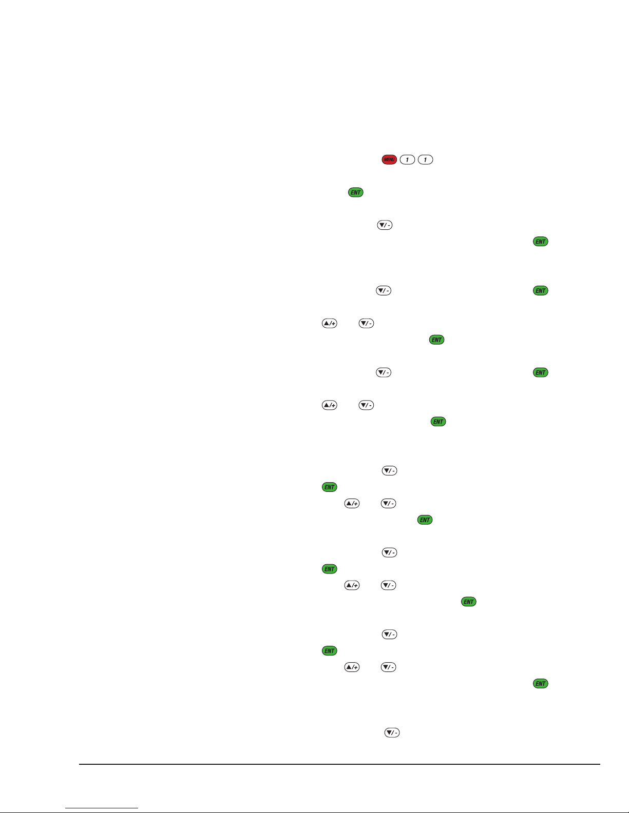
1) Press keys to enter into M11 window.
Input the pipe outer diameter through the keypad and
press key.
2) Press key to enter into M12 window. Input the
pipe thickness through the keypad and press
key.
3) Press key to enter into M14 window. Press
key to get into the option selection mode. Use keys
and to scroll up and down to the proper pipe
material, and then press key.
4) Press key to enter into M16 window. Press
key to get into the option selection mode. Use keys
and to scroll up and down to the proper liner
material, and then press key. Select “No Liner”,
if there is no liner.
5) Press key to enter into M20 window. Press
key to get into the option selection mode. Use
keys and to scroll up and down to the proper
liquid, and then press key.
6) Press key to enter into M23 window. Press
key to get into the option selection mode. Use
keys and to scroll up and down to the proper
transducer type, and then press key.
7) Press key to enter into M24 window. Press
key to get into the option selection mode. Use
keys and to scroll up and down to the proper
transducer mounting method, and then press
key.
8) Press key to enter into M25 window. The
transducer installation distance will be displayed
EUROMAG | 19
INSTALLATION AND MEASUREMENT
on the window. Based on this distance and the
transducer installation method selected above, install
the transducers on the pipe (refer to
Appendix 9.2
for
more installation details.)
9) After installation is completed, check if the triplet
(signal strength S, signal quality Q and transit-time
ratio R) are in the right range. Press keys
to enter into M90 window for visiting S and Q and
press to visit R.
10) Press to enter into window M01 to
visit the measurement result.
2.8 TRANSDUCER MOUNTING ALLOCATION
The first step in the installation process is to select an
optimal location for installing the transducers in order
to make the measurement reliable and accurate. A
basic knowledge about the piping and its plumbing
system would be advisable.
An optimal location would be defined as a long
straight pipe line full of liquid that is to be measured.
The piping can be in vertical or horizontal position.
The following table shows examples of optimal
locations.
Principles to select an optimal location:
1) Pipe must be full of liquids at the measurement
site.
2) No heavy corrosion of deposition inside of the
pipe.
3) Must be a safe location.
4) The straight pipe should be long enough to
eliminate irregular-flow-induced error. Typically, the
length of the straight pipe should be 15 times of the
pipe diameter. The longer the better.
The transducers should be installed at a pipe section
where the length of the straight pipe at upstream side
is at least 10D and at downstream side is at least 5D,
where D stands for pipe outer diameter.
5) If there are flow disturbing parts such as pumps,
valves, etc. on the upstream, the straight pipe length
should be increased (refer to figure 3 for more
details.) The disturbance strength are in the following
order (low to high): Single Bend -> Pipe Reduction /
Enlargement -> Outflow Tee -> Same Plane Multiple
Bends -> Inflow Tee -> Out of Plane Multiple Bends
-> Valve -> Pump.
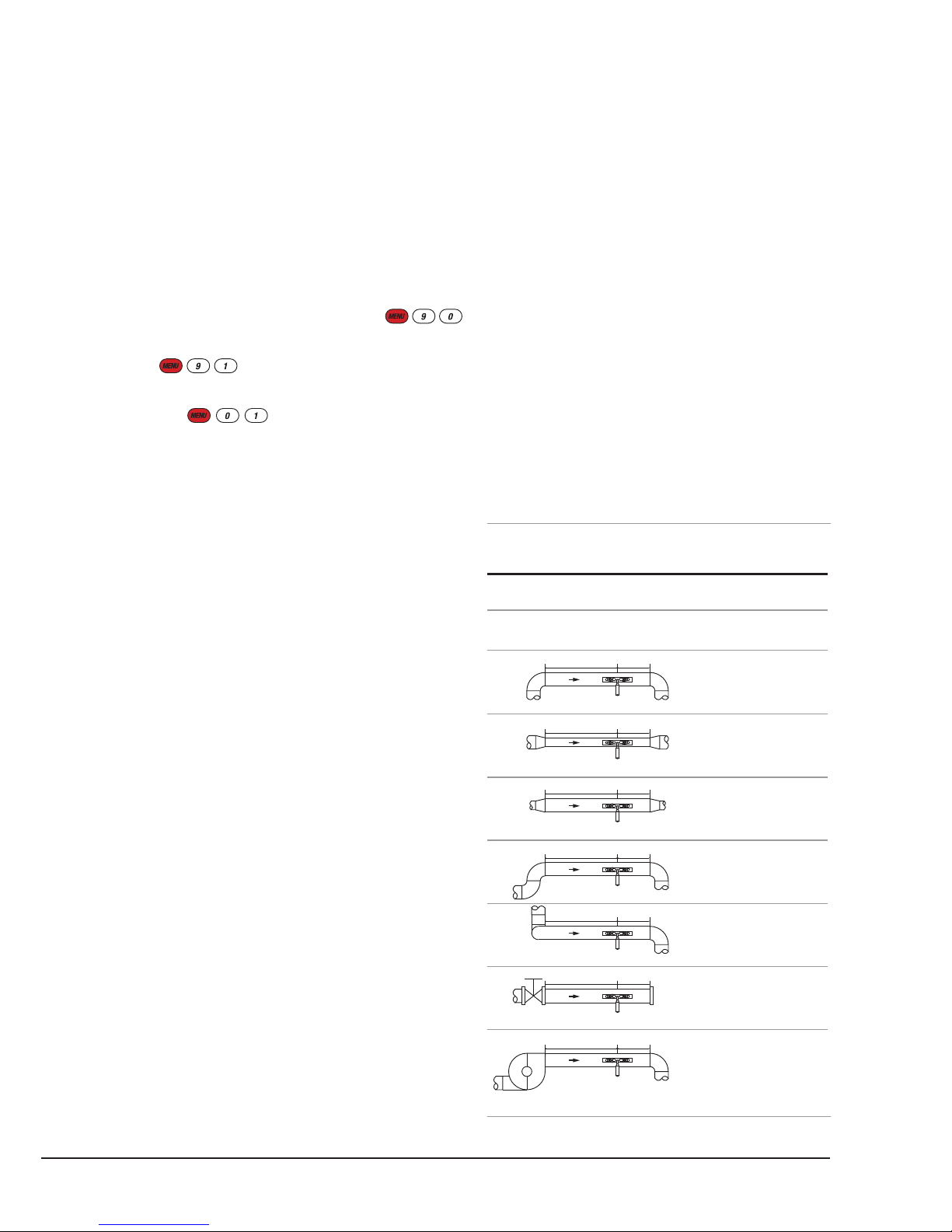
INSTALLATION SITE SELECTION
PIPING CONFIGURATION
AND TRANSDUCER POSITION
UPSTREAM
DIMENSION
Lup x
Diameters
10D
10D
10D
12D
20D
20D
30D
Ldown x
Diameters
5D
5D
5D
5D
5D
5D
5D
DOWNSTREAM
DIMENSION
f. 3
Lup
Lup
Lup
Lup
Lup
Lup
Lup
Ldown
Ldown
Ldown
Ldown
Ldown
Ldown
Ldown

20 | EUROMAG
EUROSONIC 2000
6) Make sure that the temperature on the location does
not exceed the range for the transducers. Generally
speaking, the closer to the room temperature, the
better.
7) Select a relatively new straight length of pipe line
if it is possible. Old pipe tends to have corrosions and
scale, which could affect the results. If you have to
work on an old pipe, we recommend you to treat the
corrosions and depositions as if they are part of the
pipe wall or as part of the liner. For example, you
can add an extra value to the pipe wall thickness
parameter or the liner thickness parameter to take
into account the deposition.
8) Some pipes may have a kind of plastic liner
which creates a certain amount of gaps between
liner and the inner pipe wall. These gaps could
prevent ultrasonic waves from direct travelling. Such
conditions will make the measurement very difficult.
Whenever possible, try to avoid this kind of pipe. If
you have to work on this kind of pipe, try our plug-
in transducers that are installed permanently on
the pipe by drilling holes on the pipe while liquid is
running inside.
9) When select the measurement site, you may need
to consider where to mount the flow meter main
unit. Normally, the EUROSONIC 2000 electronics are
housed in a weather-resistant enclosure. It can be
mounted in a meter shed, or a location that allows
easy access to the flow meter for programming and
servicing.
10) When select the measurement site, you may
also need to consider how to install the transducers.
Make sure you have enough spatial space for easy
operation.
2.9 TRANSDUCERS WIRING
Since the flowmeter utilizes balanced topology
for high-performance ultrasonic transmitting and
receiving, it is recommended to use high-frequency
twisted cable with shielding as the transducer cable
in order to guarantee the signal quality. Please refer
to
section 2.2
and
Appendix 9.1
on how to wire
transducers to the flow meter terminals.
2.10 TRANSDUCERS INSTALLATION
The transducers used by the flowmeter series
ultrasonic flow meter are made of piezoelectric
crystals both for transmitting and receiving ultrasonic
signals through the wall of liquid piping system. The
measurement is realized by measuring the travelling
time difference of the ultrasonic signals. Since
the difference is very small, the spacing and the
alignment of the transducers are critical factors to the
accuracy of the measurement and the performance
of the system. Meticulous care should be taken for
the installation of the transducers.
Clamp-on transducer installation steps:
1) Locate an optimal position where the straight
pipe length is sufficient (see the previous section),
and where pipes are in a favourable condition, e.g.,
newer pipes with no rust and ease of operation.
2) Calculate the transducer spacing. Just enter
the pipe, fluid and transducer information through
menu M11 to M24, the flow meter will calculate the
transducer spacing automatically. The value will be
shown in M25. Marking the transducer installation
spots on the pipe according to this spacing value.
3) Clean any dust and rust on the spot where the
transducers are to be installed. For a better result,
Table of contents
Other Euromag Measuring Instrument manuals


