Euromag EUROSONIC 2000 HH User manual

Hand Held Ultrasonic Flow Meter
EUROSONIC 2000 HH
User Manual
READ AND KEEP THESE INSTRUCTIONS
TD 204-0-ENG

EUROSONIC 2000 HH

EUROMAG | 3
INDEX
1. INTRODUCTION
1.1 Preface
1.2 Features
1.3 Flow measurement principle
1.4 Part identification
1.5 Typical applications
1.6 Data integrity and built in time keeper
1.7 Product identification
1.8 Specifications
2. MEASUREMENT
2.1 Built in battery
2.2 Power on
2.3 Keypad
2.4 Menu windows
2.5 Menu window list
2.6 Steps to configure parameters
2.7 Transducer mounting allocation
2.8 Transducer installation
2.8.1 Transducer Spacing
2.8.2 V Method Installation
2.8.3 Z Method Installation
2.8.4 W Method Installation
2.9 Installation testing
2.9.1 Signal Strength
2.9.2 Signal Quality
2.9.3 Total Transit Time and Delta Time
2.9.4 Transit Time Ratio
7
7
7
8
9
10
10
10
11
13
13
13
14
14
15
16
17
18
19
19
20
20
20
20
21
21
21

4 | EUROMAG
EUROSONIC 2000 HH
3. HOW TO CHECK AND SETUP
3.1 How to check the instrument works properly
3.2 How to check the liquid flow direction
3.3 How to change the unit readings
3.4 How to select a flow rate
3.5 How to use the totalizer multiplier
3.6 How to set the totalizer functions
3.7 How to reset totalizers
3.8 How to restore the factory defaults
3.9 How to use the damper to stabilise the flow rate
3.10 How use the zero cut off function
3.11 How to set a zero point
3.12 How to change the flow rate scale factor
3.13 How to set and lock the password
3.14 How to use the inbuilt data logger
3.15 How to use the frequency output
3.16 How to use the totalizer pulse output
3.17 How to produce an alarm signal
3.18 How to use the built in buzzer
3.19 How to use the oct pulse output
3.20 How to set the built in calender
3.21 How to adjust the lcd contrast
3.22 How to use the rs232 serial interface
3.23 How to view the totalizers
3.24 How to use the working timer
3.25 How to use the manual totalizer
3.26 How to check the serial number
3.27 How to check the battery life
3.28 How to charge the battery
4. MENU WINDOW DETAILS
5. TROUBLE SHOOTING
5.1 Power-on errors
5.2 Working status errors
5.3 Other problems and solutions
23
23
23
23
23
23
24
24
24
24
24
24
24
24
25
25
25
26
26
26
26
26
27
27
27
27
27
27
27
29
35
35
35
37

EUROMAG | 5
INDEX
6. COMMUNICATION PROTOCOL
6.1 Rs232 connector pin-out
6.2 Communication protocol
6.2.1 Basic Commands
6.2.2 Protocol Prefix Usage
6.3 The m command and the ascii codes
7. WARRANTY AND SERVICE
7.1 Warranty
7.2 Service
8. APPENDIX
8.1 Battery maintenance and replacement
8.2 Pipe size tables
8.2.1 Standard Pipe size charts for Copper
8.2.2 Standard Pipe size charts for PVC
8.2.3 Standard Pipe size charts for Steel pipe
8.2.4 Standard Pipe size charts for Cast Iron Pipe
8.2.5 Standard Pipe size charts for Ductile Iron Pipe
8.3 Sound speed tables
8.3.1 Sound Speed data of solids
8.3.2 Sound Speed in Water
8.3.3 Sound Speed in Liquids
List of figures
Figure 1: transit time flow measurement principle
Figure 2: top panel and front view
Figure 3: transducers and cables
Figure 4: keypad
Figure 5: pipe configuration and transducer placement
Figure 6: transducer clamp down
Figure 7: transducer v method mounting
Figure 8: transducer z method mounting
Figure 9: transducer w method mounting
Figure 10: rs232 wiring diagram
39
39
39
39
41
42
43
43
43
45
45
45
45
48
49
56
57
58
58
60
61
8
9
9
14
18
19
20
20
20
39

6 | EUROMAG
EUROSONIC 2000 HH

EUROMAG | 7
INTRODUCTION
1. INTRODUCTION
1.1 PREFACE
The hand held flow meter is a battery-powered ultrasonic flow meter with the capability of regular full-size
instrument. It is carefully designed for portability and ease of use.
The hand held flow meter is based on clamp-on transit-time flow measurement principle. It measures the flow
rate of liquid in a pipe from outside the pipe by using a pair of ultrasonic transducers. In general, the liquid
should fill up the pipe, and should contain very little particles or bubbles. Examples of applicable liquids are:
water (hot water, chill water, city water, sea water, etc.); sewage; oil (crude oil, lubricating oil, diesel oil, fuel
oil, etc.); chemicals (alcohol, acids, etc.); waste; beverage and liquid food, solvents and other liquids.
Due to the clamp-on technique nature, the transducer installation is simple and no special skills or tools are
required. Besides, there is no pressure drop, no moving parts, no leaks and no process contamination.
The hand held flow meter utilizes our proprietary technologies such as advanced signal processing, low-
voltage transmitting, small signal receiving with self-adapting, etc. It also incorporates the latest surface-
mounting semiconductors and mini PCB design techniques. The built-in rechargeable Ni-MH battery can work
continuously for more than 10 hours without recharge.
The hand held flow meter has also a built-in data-logger, which allows the storage of 2,000 lines of data. The
stored information can be downloaded to a PC through its RS232 connection port. The hand held flow meter
also provides digital output such as frequency output or pulsed totalizer output.
1.2 FEATURES
• ±0.5% of linearity
• ±0.2% of repeatability
• ±1% of accuracy at velocity above 0.6ft/s.
• ±0.5% when on-site calibration is available
• Bi-directional measurement
• 4 flow totalizers
• Proprietary low-voltage transmission technology
• Wide pipe size range
• 100 Pico-second time measurement resolution
• 0.5 second totalizing period
• Built-in data-logger
• Clam-on transducer. Easy to install and to maintain
• Light weight, portable. Main unit 1.2lbs.
• Also able to be used for long-term deployment

8 | EUROMAG
EUROSONIC 2000 HH
1.3 FLOW MEASUREMENT PRINCIPLE
The hand held flow meter ultrasonic flow meter is
designed to measure the velocity of liquid within a
closed conduit. It uses the well-know transit-time
technology. The transducers are a non-contacting,
clamp-on type. They do not block the flow, thus no
pressure drop. They are easy to install and remove.
The hand held flow meter utilizes a pair of transducers
that work as both ultrasonic transmitter and receiver.
The transducers are clamped on the outside of a
closed pipe at a specific distance one from each other.
The transducers can be mounted in V-method where
the sound transverses the pipe twice, or W-method
where the sound transverses the pipe four times, or
in Z-method where the transducers are mounted on
opposite sides of the pipe and the sound crosses the
pipe once. The selection of the mounting methods
depends on pipe and liquid characteristics.
The hand held flow meter operates by alternately
transmitting and receiving a frequency-modulated
burst of sound energy between the two transducers
and measuring the transit time that it takes for sound
to travel between the two transducers. The difference
in the transit time measured is directly and exactly
related to the liquid speed, as shown in the following
figure.
TRANSIT TIME FLOW MEASUREMENT PRINCIPLE
V= x
MD
sin 2Ø
∆T
Tup • Tdown
O
SPACING
DOWNSTREAM TRANSDUCER
UPSTREAM TRANSDUCER
FLOW
Tup
Tdown
REFERENCES
Øis the angle between the sound path and the flow direction
Mis the number of times the sound traverses the flow
Dis the pipe diameter
Tup is the time for the beam travelling from upstream the
transducer to the downstream transducer
Tdown is the time for the beam travelling from the downstream
transducer to the upstream transducer
∆T = Tup – Tdown
f. 1
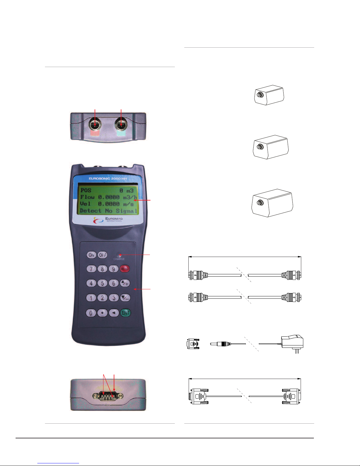
1.4 PART IDENTIFICATION
TOP PANEL AND FRONT VIEW
Top View
Front View
Bottom View
EUROMAG | 9
INTRODUCTION
f. 2 f. 3
TRANSDUCERS AND CABLES
S1-Type
(1/4”-28”) 15-100mm
M1-Type
(2”-28”) 40-700mm
L1-Type
(11”-240”) 300-6000mm
Cable 5 metre X 2
Converter Terminal and AC adapter
Cable Rs232 Interface
5m
1m
Red Terminal
Upstream Transducer
Socket
Pins for battery
recharge
Downstream Transducer
Socket
RS-232C communication
interface
LCD Display
LED
Charging
Indicator
Keypad
Red Terminal
Blue Terminal Blue Terminal

10 | EUROMAG
1.5 TYPICAL APPLICATIONS
The Eurosonic 2000 HH hand held flow meter can be
applied to a wide range of pipe flow measurements.
The pipe size ranges 0.5”-240” (15mm-6000mm). A
variety of liquid applications can be accommodated:
ultra-pure liquids, potable water, oil, chemicals,
raw sewage, reclaimed water, cooling water, river
water, sea water, plant effluent, etc. Because the
transducers are non-contacting and have no moving
parts, the flow meter will not be affected by flow
pressure or liquid properties. Standard transducers
are rated to 100ºC. Higher temperatures can be
accommodated. For further information, please
consult the manufacturer for assistance.
1.6 DATA INTEGRITY AND BUILT IN TIME KEEPER
All user-entered configuration values are stored in
the built-in non-volatile flash memory that can retain
the data for over 100 years, even when the power is
lost or turned off. Password protection is provided to
avoid inadvertent configuration changes or totalizer
resets.
A time-keeper is integrated in the flow meter. It works
as the time base for flow totalizing. The time-keeper
remains operating as long as the battery’s terminal
voltage is over 1.5V. In case of battery failure, the
time-keeper will not keep running and the time data
will lost. The user must re-enter proper time values
after the battery failure is recovered. Improper time
values will affect the totalizers as well as many other
functions.
1.7 PRODUCT IDENTIFICATION
Each set of the hand held flow meter series flow
meter has a unique product identification number
or ESN written into the software that can only be
modified with a special tool by the manufacturer.
In case of any hardware failure, please provide this
number which is located on menu window M61 when
contacting the manufacturer.
EUROSONIC 2000 HH

EUROMAG | 11
1.8 SPECIFICATIONS
Hand Set
Linearity
Repeatability
Accuracy
Response Time
Velocity
Pipe Size
Rate Units
Totalizer
Liquid Types
Security
Display
Communication Interface
Transducers
Transducer Cable
Power Supply
Data Logger
Manual Totalizer
Housing Material
Case Size
Handset Weight
0.5%
0.2%
±1% of reading at rates>0.6 ft/s. ±0.5% with on-site calibration
0-999 seconds, user-configurable
±0.03 ~ ±105 ft/s (±0.01 ~ ±30 m/s), bi-directional
0.5” ~ 240” (15 ~ 6,000mm)
Meter, Feet, Cubic Meter, Liter, Cubic Feet, USA Gallon, Imperial Gallon, Oil Barrel, USA
Liquid Barrel, Imperial Liquid Barrel, Million USA Gallons. User configurable.
7-digit totals for net, positive and negative flow
Virtually all liquids
Setup lockout. Access code needed for unlocking
4x16 characters
RS-232C, baud-rate: from 75 to 115,200 bps. Protocol made by the manufacturer.
User protocols can be made on enquiry.
Model EST-M1 for standard, other 2 models optional
Standard 2x15’ (5m), optional 2x1,500’ (500m)
3 AAA Ni-MH built-in batteries. When fully charged it will last over 10 hours of operation.
100V-240VAC for the charger
Built-in data logger can store over 2,000 lines of data
7-digit press-key-to-go totalizer for calibration
ABS. Aluminum alloy protective case
3.9”x2.6”x0.8” (100x66x20mm)
1.2 lbs (514g) with batteries
INTRODUCTION

12 | EUROMAG
EUROSONIC 2000 HH

EUROMAG | 13
MEASUREMENT
2. MEASUREMENT
2.1 BUILT IN BATTERY
The instrument can operate either from the built-in Ni-MH rechargeable battery, which will last over 10 hours
of continuous operation when fully charged, or from an external AC/power supply from the battery charger.
The battery charging circuit deliver both constant-current and constant-voltage charging methods. It has a
characteristic of fast charging at the beginning and very slow charging when the battery approaches to full
charge. Generally, when the green LED is on, the battery is nearly 95% charged, and when the red LED is off,
the battery is nearly 98% charged.
The charging current becomes automatically smaller and smaller when approaching the full battery level,
so that there should be no over-charging problem. This also means that the charging progress can last very
long. The charger can be connected to the handset all the time when an around-the-clock measurement is
required.
When fully charged, the terminal voltage reaches about 4.25V. The terminal voltage is displayed on window
M07. When running out of battery, its voltage drops below 3V. The approximate remaining working time is
indicated in this window as well.
Notice that the battery remaining working time is estimated based on the current battery voltage. It may have
some errors, especially when the terminal voltage is in the range from 3.70 to -3.90 volts.
For Battery maintenance and replacement, please refer to
Appendix A.
2.2 POWER ON
Press key to turn on the device and press to turn it off.
Once the flow meter is turned on, it will run a self-diagnostic program, checking first the hardware and then
the software integrity. If there is any anomaly, corresponding error messages will be displayed.
Generally, there should be no display of error messages, and the flow meter will go to the most commonly
used Menu Window #01 (short for M01) to display the Velocity, Flow Rate, Positive Totalizer, Signal Strength
and Signal Quality, based on the pipe parameters configured last time by the user or by the factory.
The flow measurement program always operates in the background of the user interface. This means that the flow
measurement will keep on running regardless of any user menu window browsing or viewing. Only when the user
enters new pipe parameters the flow meter will change measurement to reflect the new parameter changes.
When new pipe parameters are entered or when the
power is turned on, the flow meter will enter into a
self-adjusting mode to adjust the gain of the receiving
circuits so that the signal strength will stay within a
proper range. By this step, the flow meter finds the
best receiving signals. The user will see the progress
by the number 1, 2, or 3, located on the lower right
corner of the LCD display.
When the user adjusts the position of the installed
transducers, the flow meter will re-adjust the signal
gain automatically.
Any user-entered configuration value will be stored in
the NVRAM (non-volatile memory), until it is modified
by the user.
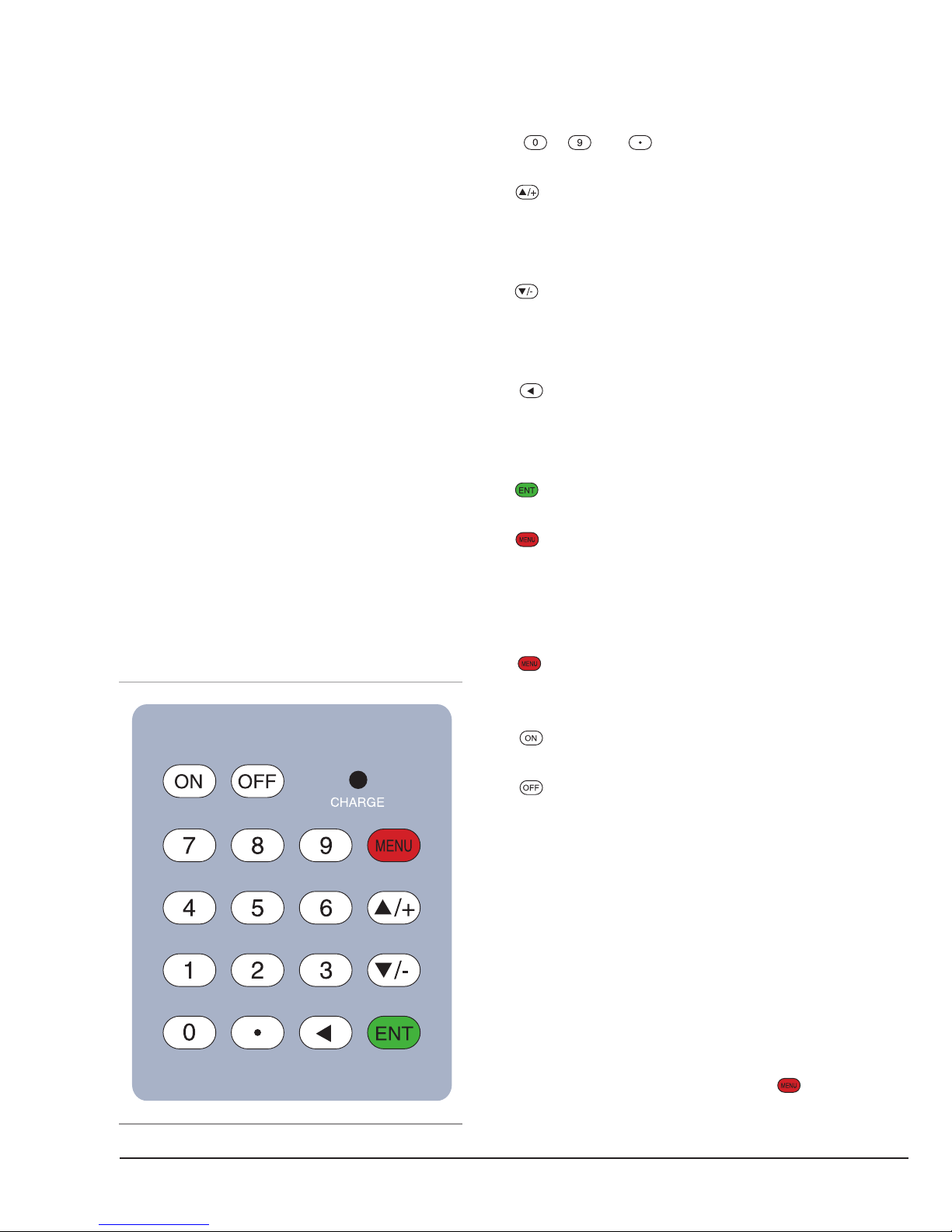
2.3 KEYPAD
The keypad of the flow meter has 16+2 keys.
Keys ~ and are keys to enter numbers.
Key is the going UP key when the user wants to
go to the upper menu window. It also works as ‘+‘
key when entering numbers.
Key is the going DOWN key when the user wants
to go to the lower menu window. It also works as the
‘–‘ key when entering numbers.
Key is the backspace key when the user wants
go left or wants to backspace the left character that
is located to the left of the cursor.
Key is the ENTER key for any input or selections.
Key is the key for the direct menu window jump
over. Whenever the user wants to proceed to a certain
menu window, the user can press this key followed
by a 2-digit number.
The key is shortened as the ‘M’ key hereafter
when referring to menu windows.
The key is for the power on.
The key is for the power off.
2.4 MENU WINDOWS
The user interface of this flow meter comprises about
100 different menu windows that are numbered by
M00, M01, M02 … M99.
There are two methods to get into certain menu
window:
1) Direct jump in. The user can press the key
followed by a 2-digit number. For example, the menu
window M11 is for setting up pipe outer diameter.
14 | EUROMAG
EUROSONIC 2000 HH
f. 4

Pressing will display the M11 menu
window immediately.
2) Press or key. Pressing the will show
to the user the lower-numbered menu window. For
example, if the current window is on M12, the display
will go to window M11 after the key is pressed
once.
There are three different types of menu windows:
1) Menu windows for number entering, e.g., M11 for
setting up pipe outer diameter.
2) Menu windows for option selection, e.g., M14 for
the selection of pipe materials.
3) Results display windows, e.g., window M00 for
displaying Velocity, Flow Rate, etc.
For number entering windows, the user can directly
press the digit keys if the user wants to modify the
value. For example, if the current window is on M11,
and the user wants to enter 219.2345 as the pipe
outer diameter, then, the flowing keys should be
pressed: .
For option selection windows, the user should first
press the key to get into option selection mode.
Then, use , , or digit key to select the right
option. Consequently, press the to make the
selection.
For example, assume your pipe material is stainless
steel and you are currently on menu window M14
which is for the selection of pipe materials (if you
are on a different window, you need press
first in order to enter into the M14 window.)
You need to press the key to get into the option
selection mode. Then, either press the and
keys to make the cursor on the line that displays “1.
Stainless Steel”, or press the key directly. At the
end, press again to make the selection.
Generally, the key must be pressed to get into
the option selection mode for option modifications.
If the “Locked M47 Open’ message is indicated on
the lowest line of the LCD display, it means that the
modification operation is locked out. In such cases,
the user should go to M47 to have the instrument
unlocked before any further modification can be
made.
2.5 MENU WINDOW LIST
M00~M09 windows are suitable for viewing the
instantaneous flow rate, net totalizer value, positive
totalizer value, negative totalizer value, instantaneous
flow velocity, date time, battery voltage and estimated
working hours for the battery.
M10~M29 windows have to be used for entering
system parameters, such as pipe outer diameter, pipe
wall thickness, liquid type, transducer type / model,
transducer installation method, etc. Transducer
installation spacing is also displayed on one of the
windows.
M30~M38 windows allow the user to enter the flow
rate unit and to configure the totalizer. User can use
these windows to select flow rate unit, such as cubic
meter or litre, as well as to turn on / off each totalizer,
or to zero the totalizers.
M40~M49 windows are for setting response time,
zeroing / calibrating the system and changing
password.
M50~M53 windows are for setting up the built-in
logger.
M60-M78 windows are for setting up time-keeper
and displaying software version, system serial
number ESN and alarms.
EUROMAG | 15
MEASUREMENT
16 | EUROMAG
M82 window is for viewing the totalizer.
M86~M89 windows are useful to configure some
parameters about the signal management, such
as automatic control, power selection and receive
window width.
M90~M94 windows are for displaying diagnostic
data. Those data are very useful when doing a more
accurate measurement.
M97~M99 are not setup windows but commands for
window copy output and pipe parameters output.
M+0~M+8 windows offer some additional functions,
including a scientific calculator, display of the total
working time, and display of the time and the flow
rate when the device is turned on and turned off.
Other menu windows such as M88 have no functions,
or functions were cancelled because they are not
applied to this version of the software.
Themajorreasonwhythemenuwindowsarearranged
in this way is to make this version compatible with
the previous ones. This will make things easier for a
user that wants to switch from a previous version to
the new one.
2.6 STEPS TO CONFIGURE THE PARAMETERS
In order to make the hand held flow meter work
properly, the user must follow the following steps to
configure the system parameters:
1. Pipe size and pipe wall thickness
2. For standard pipe, please refer to
Appendix B
for
outer diameter and wall thickness data. For non-
standard pipe, the user has to measure these two
parameters.
3. Pipe materials
For non-standard pipe material, the sound speed
of the material must be entered. Please refer to
Appendix C
for sound speed data.
4. For standard pipe materials and standard
liquids, the sound speed values have already been
programmed into the flow meter, therefore there is
no need to enter them again.
5. Liner material, its sound speed and liner thickness,
if there is any liner.
6. Liquid type (for non-standard liquid, the sound
speed of the liquid should be entered.)
7. Transducer type.
8. Transducer mounting methods (the V-method and
Z-method are the common methods)
9. Check the transducer distance displayed on window
M25 and install the transducers accordingly.
Example: For standard (commonly used) pipe
materials and standard (commonly measured) liquids,
the parameter configuration steps are as following:
1) Press keys to enter into M11 window.
Input the pipe outer diameter through the keypad and
press key.
2) Press key to enter into M12 window. Input the
pipe thickness through the keypad and press
key.
3) Press key to enter into M14 window. Press
key to get into the option selection mode. Use
keys and to scroll up and down to the proper
pipe material, and then press key.
4) Press key to enter into M16 window. Press
key to get into the option selection mode. Use
keys and to scroll up and down to the proper
liner material, and then press key. Select “No
Liner”, if there is no liner.
5) Press key to enter into M20 window. Press
key to get into the option selection mode. Use
EUROSONIC 2000 HH

EUROMAG | 17
keys and to scroll up and down to the proper
liquid, and then press key.
6) Press key to enter into M23 window. Press
key to get into the option selection mode. Use
keys and to scroll up and down to the proper
transducer type, and then press key.
7) Press key to enter into M24 window. Press
key to get into the option selection mode. Use
keys and to scroll up and down to the proper
transducer mounting method, and then press
key.
8) Press key to enter into M25 window. The
transducer installation distance will be displayed
on the window. Based on this distance, install the
transducers on the pipe now. After installation is
completed, press key to go to M01 window to
check if the measurement result is good.
The first-time users may need some time to get
familiar with the operation. However, the user friendly
interface of the instrument makes the operation quite
easy and simple. You will soon find that it is actually
very quick to configure the instrument with very little
key pressing, since the interface allows the user to
go to the desired operation directly without any extra
steps.
The following tips will facilitate the operation of this
instrument.
1) When the current window is one between M00
to M09, pressing a number key x will enter into
the M0x window directly. For example, if the current
window display is M01, pressing 7 leads to window
M07.
2) When the current window is one between M00 to
M09, pressing key will lead to window M90 for
displaying diagnostic data. Press key again to
return to the previous window. Press the key to
go to window M11.
When the current window is M25, pressing key
will lead to window M01.
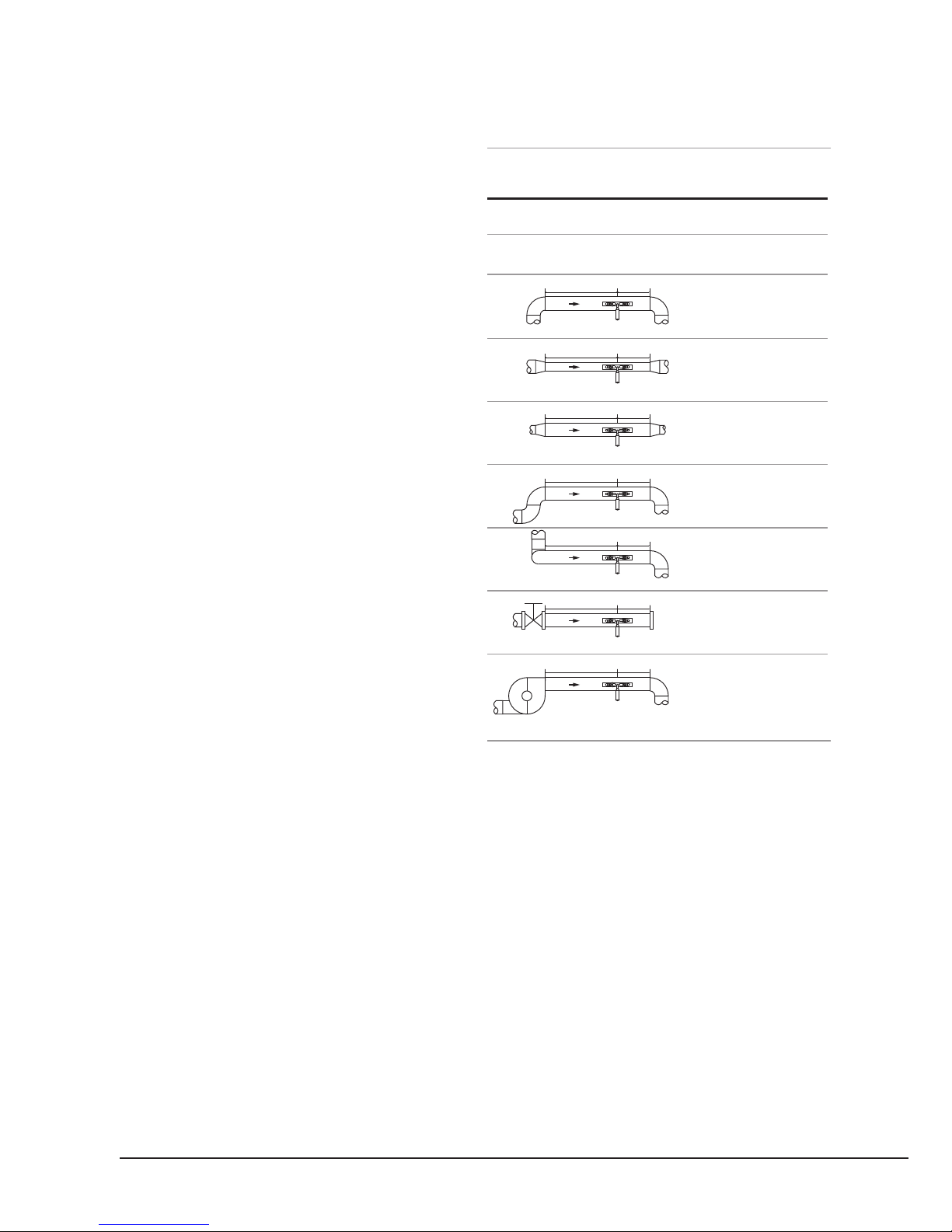
2.7 TRANSDUCER MOUNTING ALLOCATION
The first step in the installation process is to select an
optimal location for installing the transducers in order
to make the measurement reliable and accurate. A
basic knowledge about the piping and its plumbing
system would be advisable.
An optimal location would be defined as a long
straight pipe line full of liquid that is to be measured.
The piping can be in vertical or horizontal position.
The following table shows examples of optimal
locations.
Principles to select an optimal location:
1. The straight pipe should be long enough to
eliminate irregular-flow-induced error. Typically, the
length of the straight pipe should be 15 times of the
pipe diameter. The longer the better. The transducers
should be installed at a pipe section where the length
of the straight pipe at upstream side is at least 10D
and at downstream side is at least 5D. Besides, the
transducer installation site should be at least 30D
away from the pump. Here D stands for pipe outer
diameter. Refer to the following table for more
details.
2. Make sure that the pipe is completely full of liquid.
3. Make sure that the temperature on the location does not
exceed the range for the transducers. Generally speaking,
the closer to the room temperature, the better.
4. Select a relatively new straight pipe line if it is
MEASUREMENT
18 | EUROMAG
EUROSONIC 2000 HH
possible. Old pipe tends to have corrosions and
depositions, which could affect the results. If you
have to work on an old pipe, we recommend you to
treat the corrosions and depositions as if they are part
of the pipe wall or as part of the liner. For example,
you can add an extra value to the pipe wall thickness
parameter or the liner thickness parameter to take
into account the deposition.
5. Some pipes may have a kind of plastic liner
which creates a certain amount of gaps between
liner and the inner pipe wall. These gaps could
prevent ultrasonic waves from direct travelling. Such
conditions will make the measurement very difficult.
Whenever possible, try to avoid this kind of pipes. If
you have to work on this kind of pipe, try our plug-
in transducers that are installed permanently on
the pipe by drilling holes on the pipe while liquid is
running inside.
PIPE CONFIGURATION AND TRANSDUCER PLACEMENT
2.8 TRANSDUCER INSTALLATION
The transducers used by the ultrasonic flow meter are
made of piezoelectric crystals both for transmitting
and receiving ultrasonic signals through the wall of
liquid piping system. The measurement is realized
by measuring the travelling time difference of the
ultrasonic signals. Since the difference is very small,
the spacing and the alignment of the transducers are
critical factors to the accuracy of the measurement
and the performance of the system. Meticulous
care should be taken for the installation of the
transducers.
PIPING CONFIGURATION
AND TRANSDUCER POSITION
UPSTREAM
DIMENSION
Lup x
Diameters
10D
10D
10D
12D
20D
20D
30D
Ldown x
Diameters
5D
5D
5D
5D
5D
5D
5D
DOWNSTREAM
DIMENSION
f. 5
Lup
Lup
Lup
Lup
Lup
Lup
Lup
Ldown
Ldown
Ldown
Ldown
Ldown
Ldown
Ldown

EUROMAG | 19
MEASUREMENT
Steps to the installation of the transducers:
Locate an optimal position where the straight pipe
length is sufficient (see the previous section), and
where pipes are in a favourable condition, e.g., newer
pipes with no rust and ease of operation.
Clean any dust and rust on the spot where the
transducers are to be installed. For a better result,
polishing the pipe outer surface with a sander is
strongly recommended.
Apply adequate ultrasonic couplant (grease, gel or
Vaseline)* on to the transducer transmitting surface
as well as to the installation spot on the pipe surface.
Make sure there is no gap between the transducer
transmitting surface and the pipe surface.
Extra care should be taken to avoid any sand or
dust particles left between the pipe surface and the
transducer surface.
Horizontally lined pipes could have gas bubbles
inside the upper part of the pipe. Therefore, it is
recommended to install the transducers horizontally
by the side of the pipe.
There are three ways to mount the transducers on
the pipe: by magnetic force, by clamp-on fixture and
by hand. If the pipe material is metal, the magnetic
force will hold the transducer on the pipe. Otherwise,
you may either simply hold the transducer handle
and press it against the pipe (for S-type only) if you
just need a quick measurement, or, you may use or a
metal strip or the provided clamp fixture to install the
transducers (see the figure 6.)
TRANSDUCER CLAMP DOWN
2.8.1 TRANSDUCER SPACING
The spacing value shown on menu window M25
refers to the distance of inner spacing between the
two transducers (see the following figure). The actual
distance of the two transducers should be as close as
possible to this spacing value.
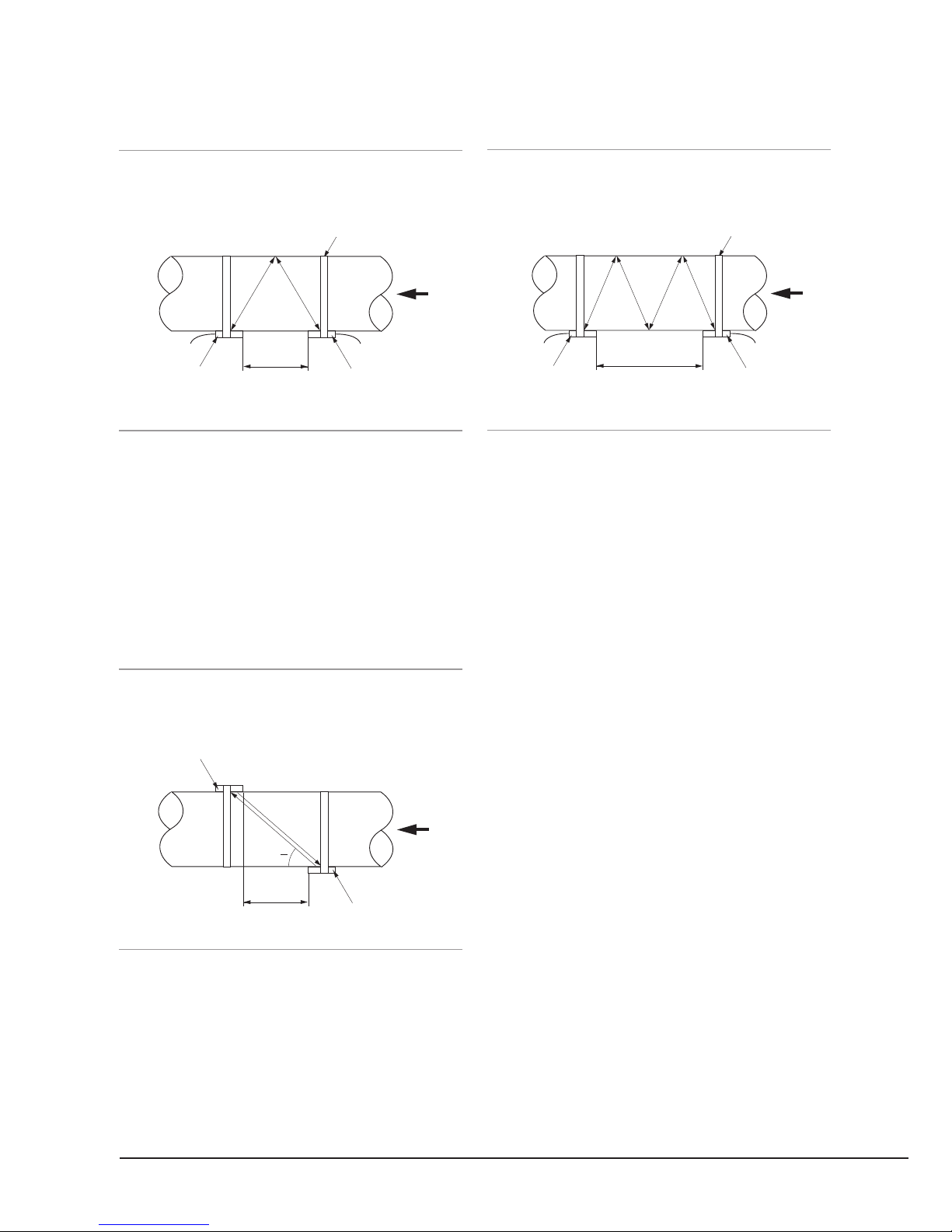
2.8.2 V METHOD INSTALLATION
V-method installation is the most widely used method
for daily measurement with pipe inner diameters
ranging from 20 millimetres to 300 millimetres. It is
also called reflective method.
f. 6
NOTE
IT IS RECOMMENDED TO USE
THE CONDUCTIVE GEL PRODUCT
FROM LIVINGSTONE, AS THE
ULTRASONIC COUPLANT FOR
SAFETY CONSIDERATIONS. OTHER
COUPLANT, SUCH AS GREASE,
GEL, AND VASELINE, CAN BE USED
AS ALTERNATIVES, BUT AT YOUR
OWN RISK.
20 | EUROMAG
EUROSONIC 2000 HH
TRANSDUCER V METHOD MOUNTING
2.8.3 Z METHOD INSTALLATION
Z-method is commonly used when the pipe diameter
is between 100 millimetres’ and 500 millimetres.
This method is the most direct for signal transfer and
can therefore provide better results than V method on
many applications.
TRANSDUCER Z METHOD MOUNTING
2.8.4 W METHOD INSTALLATION
W-method is usually used on plastic pipes with a
diameter from 10 millimetres to 100 millimetres.
This method can be effective on smaller pipes that
have internal deposits.
TRANSDUCER W METHOD MOUNTING
2.9 INSTALLATION TESTING
After completion of the transducer installation, the
user should check the following items: the receiving
signal strength, the signal quality Q value, the delta
time (travelling time difference between the upstream
and the downstream signals), the estimated liquid
sound speed, the transit time ratio, and etc. As
such, one can be sure that the flow meter is working
properly and the results are reliable and accurate.
2.9.1 SIGNAL STRENGTH
Signal strength indicates the amplitude of receiving
ultrasonic signals by a 3-digit number. [000] means
there is no signal detected and [999] refers to the
maximum signal strength that can be received.
Although the instrument works well when the signal
strength ranges from 500 to 999, stronger signal
strength should be pursued, because a stronger
signal means a better result. The following methods
are recommended to obtain strong signals:
1) If the current location is not good enough for
a stable and reliable flow reading, or if the signal
f. 9
sound
path
sound
path
spacingdownstream
transducer
upstream
transducer
flow
clamp fixture
f. 8
Tup
Tdown
spacing
downstream
transducer
upstream
transducer
flow
O
f. 7
sound
path
spacingdownstream
transducer
upstream
transducer
flow
clamp fixture
Table of contents
Other Euromag Measuring Instrument manuals


