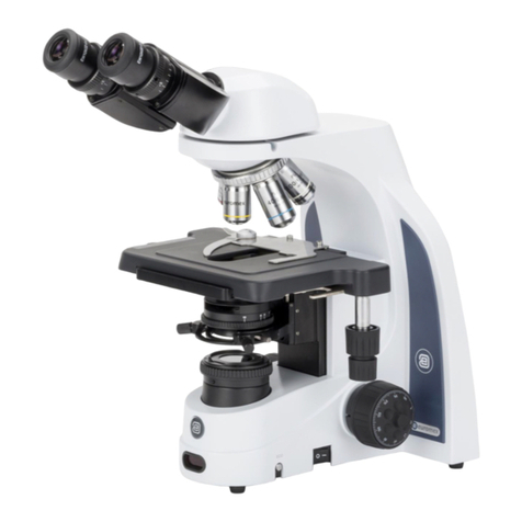
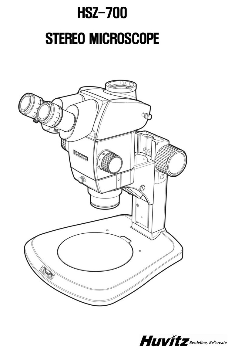
Euromex NexiusZoom-Range User manual

INSTRUCTION MANUAL
EUROMEX
STEREOMICROSCOPES
NexiusZoom-Range
and
NexiusZoom EVO-Range
EUROMEX Microscopen B.V.
HOLLAND
www.euromex.com
100 Lauman Lane, Suite A, Hicksville, NY 11801
Tel: (877) 877-7274 | Fax: (516) 801-2046
Email: [email protected]
www.microscopeinternational.com
'LVWULEXWHGE\

2
1.0 Introduction
With your purchase of a EUROMEX NexiusZoom-Range or NexiusZoom EVO-Range stereo
microscope you have chosen for a quality product. The EUROMEX NexiusZoom-Range and
NexiusZoom EVO-Range stereo are developed for professional industrial purposes, scientific
research and education because of the excellent optical and mechanical properties while very
attractively priced
The stereo microscope consists of two separate microscope tubes which are combined as a unit,
in order to focus them simultaneously on the object. Each tube has prisms, achromatic objectives
and a widefield eyepiece in order to obtain a large, flat field of view. Both eyes are looking at the
object under a different angle to reach a deep stereoscopic image.
The maintenance requirement is limited when using the microscope in a decent manner.
This manual describes the construction of the microscope, how to use the microscope and
maintenance of the microscope. For some versions, like boom stand models, the microscope will
be supplied with an additional manual.
2.0 Index
1.0 Introduction
2.0 Index
3.0 Construction of the microscope
4.0 Functions of the microscope
5.0 Preparing the microscope for use
6.0 Working with the stereo microscope
7.0 Maintenance and cleaning
8.0 Optional accessories
3.0 Construction of the microscope
The names of the several parts are listed below and are indicated in the picture:
A) Eyepiece K) Focusing knob(s)
B) Diopter correction L) Intensity controller for incident illumination
C) Head fixation screw M) Object clip
D) Objective cover N) On/Off switch
E) Intensity controller for transmitted illumination O) Object plate with transmitted illumination
F) Stand base below it.
G) Photo tube
H) Stand (rack and pinion version)
I) Zoom knob(s)
J) Incident illumination

3
G)
A)
B)
H)
I )
C)
D) J)
K)
E) L)
M)
N)
F)
O)
NexiusZoom NZ.1903-S

4
4.0 Functions of the microscope
The stereo microscope consists of a stand with holder/focusing system, in which the stereo head
is placed and locked with fixation screw(D) .
Always hold the microscope at its pillar and base when moving it.
4.1 Tube
The microscope heads of the NexiusZoom-Range are equipped with a 45tube, which are
rotatable over 360. Each type has a diopter adjustment ring on both eyepiece tubes.
4.2 Optical specifications
The microscopes of the NexiusZoom-Range are equipped with 2 zoom objectives and a pair of
wide field WF10x/22 eyepieces. In the tabel below all available models are listed.
The microscopes of the NexiusZoom- EVO Range are equipped with 2 zoom objectives and a pair
of wide field WF10x/23 eyepieces. In the tabel below all available models are listed

5
4.3 Object stage
The stand is equipped with an object stage with a semi transparent stage plate (O) and 2 object
clips (M).
4.4 Focusing
With the focusing knobs (K) the object can be sharply focussed.
4.5 Magnification adjustment NexiusZoom
The microscopes are equipped with 2 achromatic zoom objectives. By using the zoom knobs (I)
the magnification can be adjusted in a smooth, stepless way.
4.6 Illumination
The stand is equipped with transmitted and incident LED illumination of 3 Watt. The illuminators
can be used simultaneously. Intensity of the LED’s can be controlled using controllers (E) and (L).

6
5.0 Preparing the microscope for use
Take the stereo microscope out of its packing and put it on a firm stable table. Connect the power
cable to the mains supply and switch on the microscope. Place the eyeshades onto the eyepieces.
Sit comfortably down behind the microscope and take a relaxed position while viewing through the
eyepieces (A). The third (photo) tube of the trinoculair versions is packed in the lid of the
styrofoam packing. Take it out and place it onto the microscope.
6.0 Working with the stereo microscope
The interpupillary distance
In order to obtain a smooth “compound” image, one should go through the below steps.
The correct interpupillary distance is reached when one round image is seen in the field of view
(see image below). This distance can be set by either pulling the tubes towards each other or
pulling them from each other. This distance is different for each observer and thus should be set
individually. When more users are working with the microscope it is recommended to remember
your interpupillary distance for a quick set up during new microscopy sessions.
Field of view before Field of view after
adjustment adjustment
The correct eye point
The eye point is the distance from the eyepiece to the user’s pupil. To obtain the correct eye point,
move the eyes towards the eyepieces until a sharp image is reached at a full field of view.

7
6.1 Setting the eyepieces in order to have a sharp image over the complete zoom range

8
6.2 Photo and video
For trinocular models, slide the camera with mounted c-mount adapter into the 23,2mm tube of
the phote port. For focussing loosen the ring (A) and slowly unscrew the tube (B) you will be able
to match parfocality of the camera with the view through the eyepieces. Adjustment can be made
by raising/lowering the height of the camera (C). Take an easy-to-view specimen and focus the
image through the microscope’s eyepieces (with dioptre adjustment set on “0”). Afterwards,
perform this height adjustment procedure while watching the image on the computer screen. In
this case, once you have obtained parfocality in the device, screw the ring (A) back.
Digital cameras can also be used in combination with a binocular. Simply remove the eyepiece
and place the camera adapter ring inside the eyepiece tube. Then place the camera with mounted
c-mount adapter into the eyepiece tube. Focus the digital image with the coarse and fine controls
of the microscope. Also see instruction on next page.
Follow the manual that comes with the camera for camera operation.

9
To Mount the CMEX camera’s on an binocular microscope please do the following:
1) Remove one of the eye pieces of the microscope. First un-screw the Philips type locking screw that secures
the eye piece.
2) Insert the 30,5mm adapter into the eye-piece tube, rubber ring* facing down.
3) Insert the camera into the adapter tube.
4) The system is now set-up
*the rubber ring is meant to fix the adapter tube tightly in the eye piece tube. During first use it can
be that some force needs to be issued to put it in. The rubber ring can be removed if wanted.
1
2
3

10
7.0 Maintenance and cleaning
Always place the dustcover over your microscope after use. Keep the eyepiece and objectives
always mounted on the microscope to avoid dust entering the instrument.
Cleaning the optics
When the eyepiece lens or front lens of the objective ares dirty they can be cleaned by wiping a
piece of lens paper over the surface (circular movements). When this does not help put a drop of
alcohol on the lens paper. Never put xylol or alcohol directly on the lens! Please note that
Euromex offers a special microscope cleaning kit: PB.5275
It is not necessary –and not recommended –to clean the lens surfaces at the inner side of the
objectives. Sometimes dust can be removed with high pressured air.
Caution
Cleaning cloths containing plastic fibers can damage the coating of the lenses!
Maintenance of the stand
Dust can be removed with a brush. In case the stand or table is really dirty the surface can be
cleaned with a non-aggressive cleaning product.
All moving parts like the height adjustment or the coaxial course and fine adjustment contain ball
bearings that are not dust sensitive. With a drop of sewing-machine oil the bearing can be
lubricated.
7.1 Maintenance of the stand
Dust can be removed with a brush. In case the stand or stage plate is really dirty the surface can
be cleaned with a non-aggressive cleaning product.

11
7.2 Replacing the fuse
To change the fuse, following the procedures below:
1. Remove the power cord from the back of the microscope
2. Locate the fuse compartment, which has a Fuse image. It is typically located beneath the
power connector.
3. Remove the fuse compartment. To do so, insert a flat head screw driver in between the
metal power tines and gently pry the fuse compartment loose with a slight down and out
motion.
4. Insert the new fuse into the compartment, and then replace the fuse compartment back to
where it was originally.
5. Power up the microscope and test
Note: Fuse may blow in order to protect internal damage to the microscope. And in most cases, replacing the fuse with the correct voltage will
resolve the issue. However, should you encounter a blown fuse frequently, please contact your distributor for further assistance.

12
8.0 Optional accessories
NZ.5302 NexiusZoom binocular head with eyepieces
NZ.5303 NexiusZoom trinocular head with eyepieces
NZ.6010 Pair HWF 10x/22 mm eyepieces
NZ.6015 Pair HWF 15x/16 mm eyepieces
NZ.6020 Pair HWF 20x/12 mm eyepieces
NZ.6110 HWF 10x/22 mm eyepiece with 1/100 mm micrometer
NZ.6099 Pair of eyeshades
NZ.8905 Auxiliary lens 0.5x, working distance 187 mm
NZ.8907 Auxiliary lens 0.75x, working distance 125 mm
NZ.8915 Auxiliary lens 1.5x, working distance 50 mm
NZ.8920 Auxiliary lens 2.0x, working distance 33 mm
NZ.8950 Protection glass for NexiusZoom head
NZ.9010 Ergo rack and pinion stand with diascopic and incident LED illuminators
NZ.9015 Ergo pillar stand with LED diascopic and incident illuminators
NZ.9020 Universal one arm stand without NexiusZoom head holder
NZ.9030 Universal double arm stand without NexiusZoom head holder
NZ.9090 NexiusZoom head holder for NZ.9020/9030
65.980 Articulated arm stand with table clamp without NexiusZoom head holder
68.981 Head 76 mm holder for black universal stand 65.980
NZ.9570 Pair object clamps for stage
NZ.9833 C-mount adapter with 0.33x lens for 1/3” cameras(only for NZ.1903 models)
NZ.9850 C-mount adapter with 0.5x lens for 1/2” cameras (only for NZ.1903 models
NZ.9956 Stage plate black/white, Ø 95 mm
LE.1973 Ring light illuminator with 144 LED’s and segment controller
AE.1112 Object micrometer 50 mm divided in 500 parts on glass slide 76 x 26 mm
More accessories can be found on our website or ask your reseller

13
NZ and EVO EV2
100 Lauman Lane, Suite A, Hicksville, NY 11801
Tel: (877) 877-7274 | Fax: (516) 801-2046
Email: [email protected]
www.microscopeinternational.com
'LVWULEXWHGE\
This manual suits for next models
1
Other Euromex Microscope manuals
