Euromex iScope Series User manual

Page 2
The iScope series has been designed with all kind of Life Sciences applications and great durability
in mind. This resulted in a modern, robust and high level microscope for everyday use, equipped
with excellent optical and mechanical components. Specific attention to production methods
resulted also in an excellent price/performance ratio
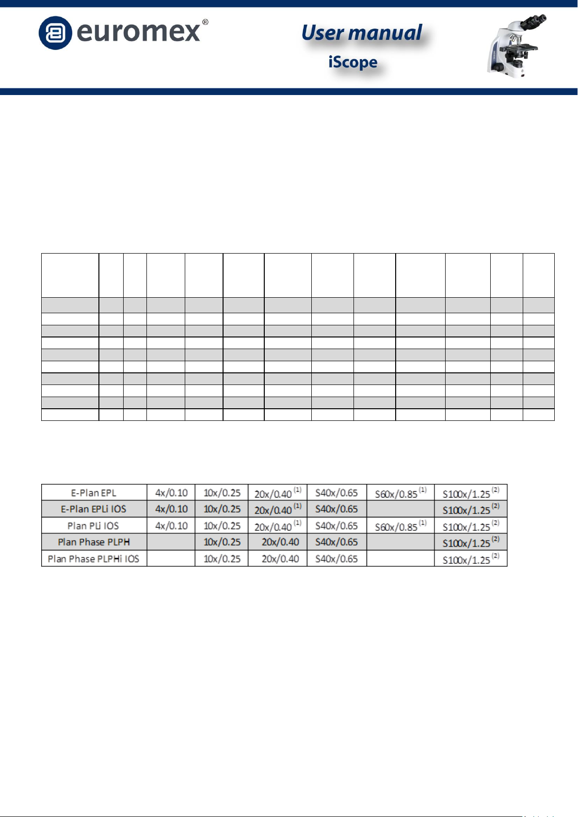
Models
Objectives
(1) optional objectives (2) oil immersion objectives
Models Bino Trino
EWF 10x
20 mm
EWF 10x
22 mm
E-Plan
objectives
Plan Phase
objectives
E-Plan IOS
objectives
Plan IOS
pbjectives
Plan Phase
IOS
objectives
Mechanical
rackless
stage
iCare
sensor
Köhler
LED
IS.1152-EPL • • • •
IS.1153-EPL • • • •
IS.1152-PLPH • • • •
IS.1153-PLPH • • • •
IS.1152-EPLi • • • • •
IS.1153-EPLi • • • • •
IS.1152-PLi • • • • • •
IS.1153-PLi • • • • • •
IS.1152-PLPHi • • • • • •
IS.1153-PLPHi • • • • • •

Page 3
The S40x, S60x and S100x objectives are equipped with a spring mount, to prevent damage to the
front lens and the slide.
The Numeric Aperture - N.A. –of the objective is an indication for the resolving power of the
objective.
The total magnification can be calculated by multiplying the magnification of the eyepiece with the
magnification of the objective. The magnifications are displayed in the table below:
Eyepiece
Objective
Magnification
10x
4x
40x
10x
10x
100x
10x
40x
400x
10x
60x
600x
10x
100x
1000x
Page 4
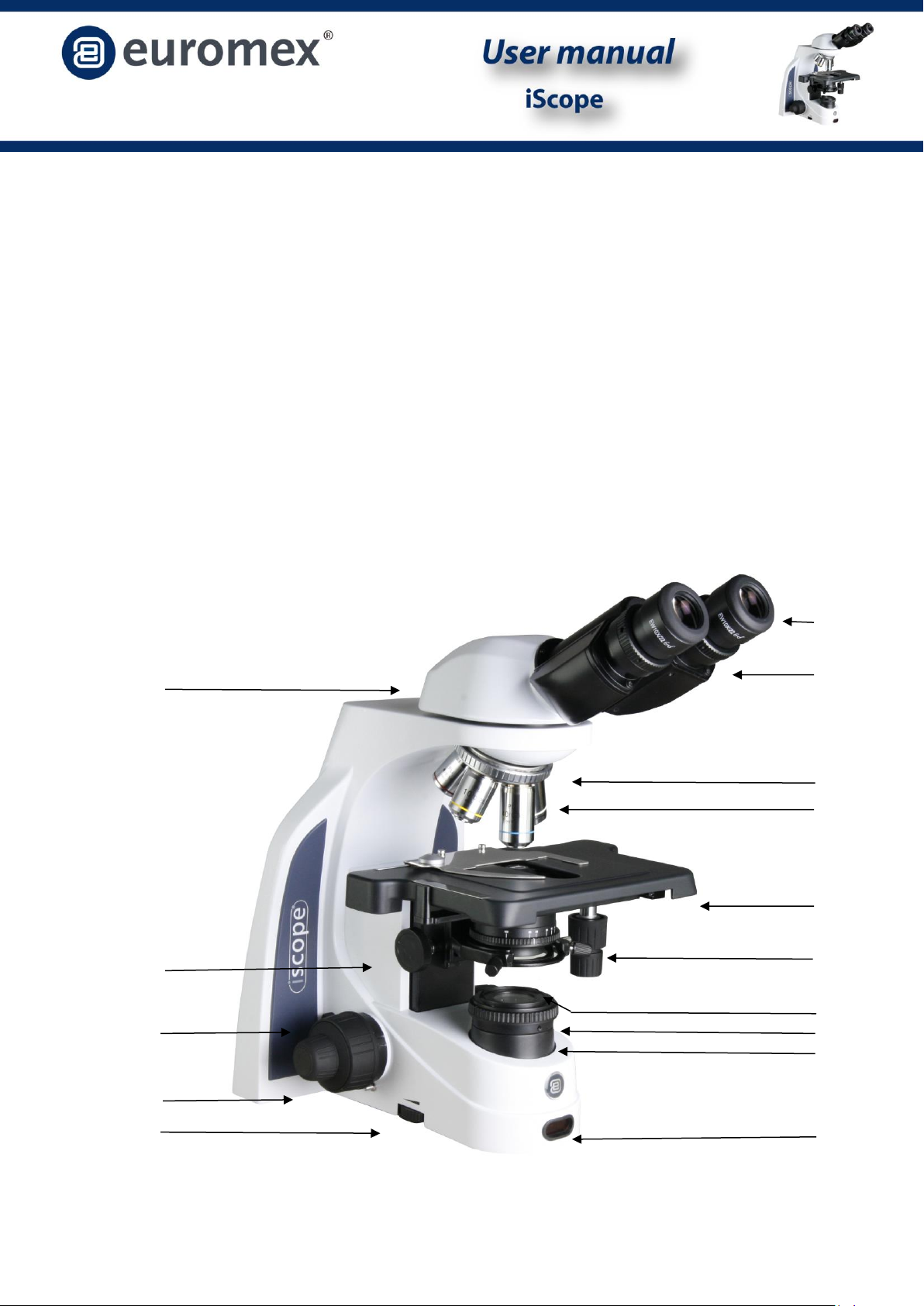
Construction of the microscope
The names of the several parts are listed below and are indicated in the picture:
A) Microscope head N) Slide protection handle
B) Eyepieces O) Height adjustment condenser
C) Diopter adjustment I) Kohler iris diaphragm
D) Nosepiece J) Collector lens
E) Objectives K) iCare sensor
F) Stage with X-Y mechanical stage L) Light intensity adjustment knob
G) X-Y stage controls M) Coaxial coarse adjustment
H) Condenser with iris diaphragm
I) Kohler iris diaphragm
J) Collector lens
A
B
A
D
E
F
G
J
I
H
K
L
M
C
N
O
Page 5
Preparing the iScope microscope for use
Your microscope is a delicate product, please handle it with care.
Carefully remove the items from their packing and place them on a flat, firm surface. Please do not
expose the microscope to direct sun light, high temperatures, damp, dust or acute shake. Please
make sure the worktable is flat and horizontal.
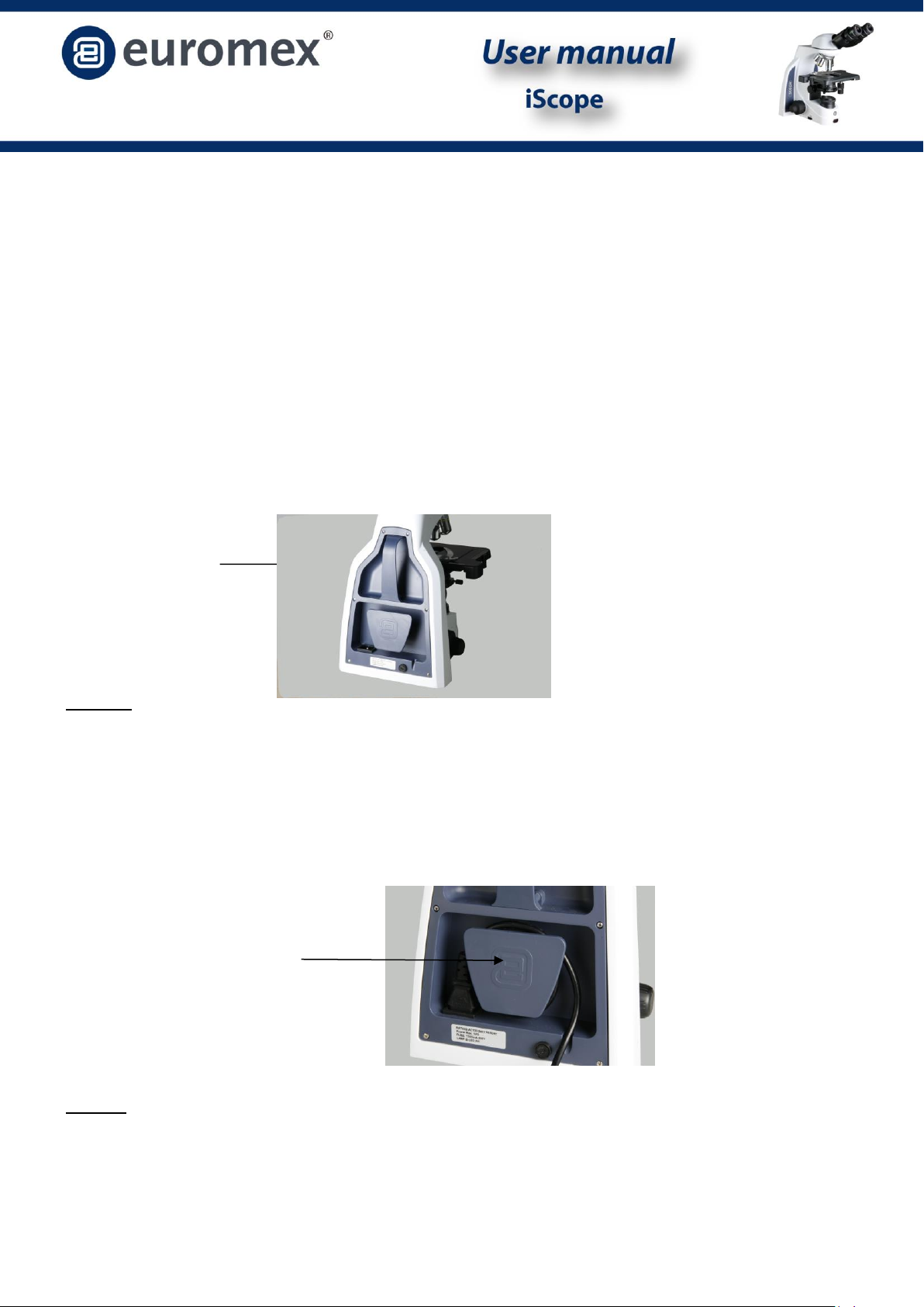
When moving the microscope, use the left hand to hold the transport handle at the backside of
the microscope and with the right hand the bottom of the microscope.
Transport handle
Caution! Holding the microscope with the stage, the
stage focusing knob will damage the microscope.
Insert the power cord in the backside of the microscope and use the cable storage CSS - Cable
Storage System –to store the cable after use
CSS - Cable Storage System
Caution! If the bacterial solution or water splatters over the stage, objective or head, pull out the
power cord immediately and dry the microscope.
For safety reasons, make sure the power switch is turned off and remove the plug before
A
B
C
D
X
E
F
G
H
I

Page 6
replacing the led unit or fuse
Assembling Steps
Euromex Microscopes will always try to keep the number of assembly steps for their customers as
low as possible but in some cases there are some steps to be taken. The steps mentioned below
are often not necessary but described for your convenience nonetheless.
Mounting the objectives
1. Rotate the coarse focusing knob to lower the stage to the lowest position.
2. Install the objectives into the objective nosepiece from the lowest magnification to the highest
in a clockwise direction from the rear side of the microscope. When using the microscope, start
using the low magnification objective (4X or 10X) to search for specimen and focus, and then
continue with high magnification objective to observe.
The microscope head
The standard iScope series configuration is supplied with the head assembled. However, if your
order contains the fluorescence it should be mounted first. The dovetail on the bottom side of
these parts fits into the slot on the top side of the other parts.
Placing the eye pieces
1. Remove the cover of eyepiece tube.
2. Insert the eyepiece into the eyepiece tube
The eyeshades
Each eyepiece has its rubber eyeshade. This prevents damage to the lens, and prevents stray light.
The eyeshade can simply be slipped over the eyepiece.
Connecting the power cord
The iScope series microscopes supported a wide range of operating voltages: 100 to 240V. Please
use a grounded power connection.
1. Make sure the power switch is off before connecting.
2. Insert the connector of power cord into the iScope power socket, and make sure it
connects well.
3. Insert the other connector into the mains socket, and make sure it connects well.
Don’t use bend or twist the power cord, it will get damaged. Using the special cord supplied by
Euromex. If it’s lost or damaged, choose one with the same specifications.
Page 7
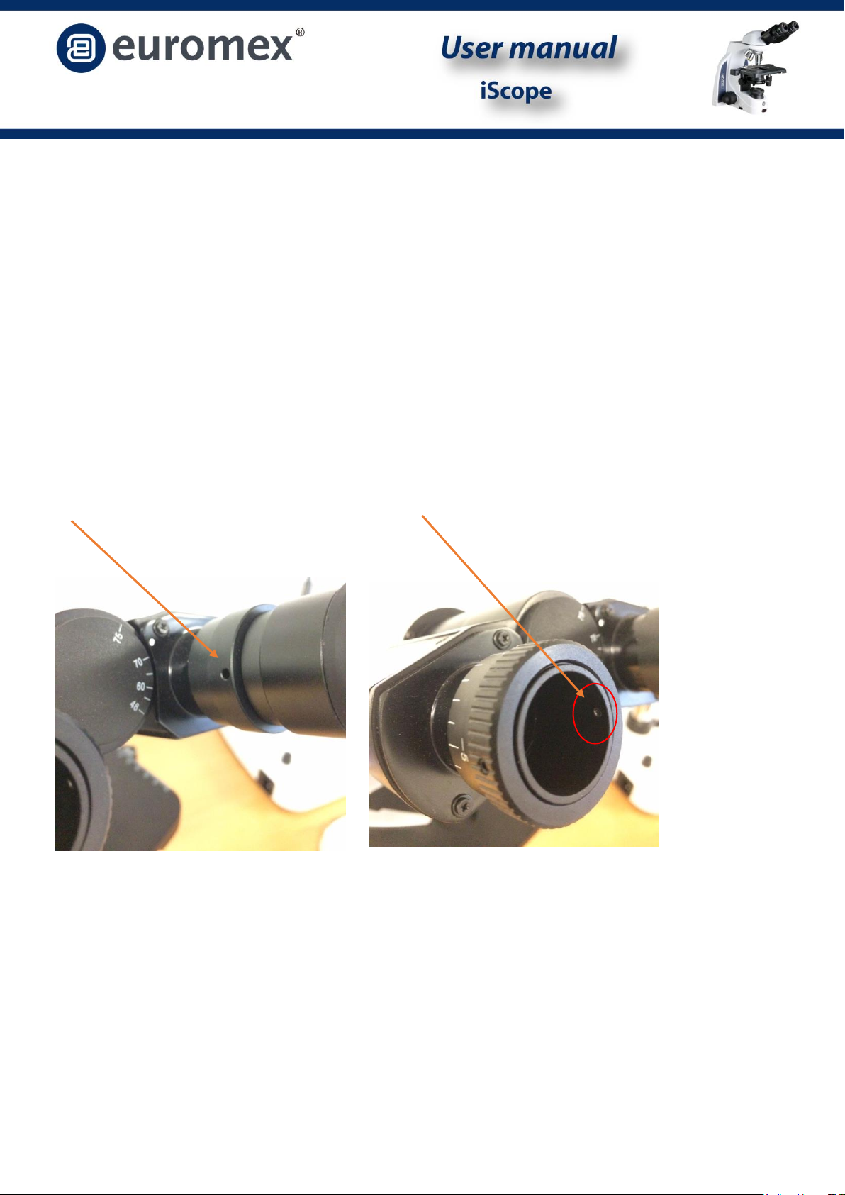
Locking the eyepieces on iScope
For models without diopter adjustment, please find the screw for locking the eyepiece on the tube ring
here(A). Please note that location can be slightly rotated from model to model
For models with diopter adjustment, take out the eyepiece and look into the tube to find the right position
of screw(B)
A B

Page 8
Operation:
Setting up the illumination
For optimum effect in contrast and resolution one should follow the below procedure:
Place a specimen on the object stage and focus using the 4x objective, with a fully opened iris diaphragm.
Turn light intensity to lowest position, then look through the eyepiece(s) and turn up to
comfortable intensity level
Turn the condenser in the highest position(for phase contrast models, please set condenser to
bright field position).
Close the iris diaphragm, until it is just visible on the edge of the field of view.
The microscope is properly set for use with the 4x objective. For each other magnification in bright field use
this procedure should be repeated to ensure the best balance between contrast and resolution. Phase
contrast use will be explained later in this manual.
Place the specimen slide
1. Push the arm of the specimen holder backwards.
2. Release the arm slowly clamping the slide with the cover glass facing up.
3. Rotating the X and Y-axis knob will move the specimen to the center for alignment with the
center of the objective.
Focusing and slide protection
1. Select the objective 4x to the optical path.
2. Rotate the position screw to top, observe the right eyepiece with right eye. Rotate the
coarse focusing knob until the image appears.
3. Rotate the fine focusing knob for detailed focusing
4. When focused with S100x objective, lock the slide protection handle. The slide protection
handle protects the slide by limiting the travel of the table. This way the objectives will not
touch or break your slides.
Adjusting the focusing tension
The iScope series microscope focusing knobs can be adjusted for tension. You can set it from light
to heavy according your own preference. Please note that when the specimen leaves the focus
plane after focusing or the stage declines itself, the tension should be set higher. To tighten the
focusing arm (more heavy), rotate the tension adjustment ring according to the arrowhead
pointed; to loosen it, please turn it in the reverse direction.
The interpupillary distance

Page 9
Using a binocular (or trinocular) tube is less tiring for the eyes than the use of a monocular tube. In
order to obtain a smooth “compound” image, one should go through the below steps.
The correct interpupillary distance is reached when one round image is seen in the field of view
(see image below). This distance can be set by either pulling the tubes towards each other or
pulling them from each other. This distance is different for each observer and thus should be set
individually. When more users are working with the microscope it is recommended to remember
your interpupillary distance for a quick set up during new microscopy sessions. The iScope’s
swiveling eyepiece tube can be rotated 360º. You can select corresponding eye point height
according to your own preference.
Field of view before Field of view after
adjustment adjustment
The correct eye point
The eye point is the distance from the eyepiece to the user’s pupil. To obtain the correct eye
point, move the eyes towards the eyepieces until a sharp image is reached at a full field of view.
Adjusting the diopter
Using a binocular (or trinocular) tube is less tiring for the eyes than the use of a monocular tube. In
order to obtain the right interpupillary setting, one should go through the below steps.
Turn the diopter adjustment ring of the left eyepiece tube until the scale shows the same
reading as on the indicator.
Close the right eye and focus the left tube by means of the coarse- and fine adjustment knobs
Close the left eye and focus the right tube with the diopter adjustment ring.
This procedure should be followed by each individual user. When more users are working with the
iScope microscope it is recommended to remember your diopter setting for a quick set up during
new microscopy sessions.
Abbe condenser
Beneath the object stage an Abbe condenser N.A. 12.5 is mounted. The condenser can be adjusted
in height by means of a rack and pinion movement and knob. With this one can focus the light on

Page 10
the specimen by which the contrast can be optimized. The condenser is factory pre-centered. If
needed the following procedure can be followed to center the condensor.
1. Move the condenser to the highest position.
2. Select the 10x objective to the light path and focus the specimen.
3. Rotate the field diaphragm adjustment ring to put the field diaphragm to the smallest
position.
4. Rotate the condenser up-down knob, and adjusting the image to be clearest.
5. Adjusting the center adjustment screw and put the image to the center of the field of view.
6. Open the field diaphragm gradually. If the image is in the center all the time and inscribed
to the field of view, it shows condenser has been centered correctly.
The field (Köhler) diaphragm
By limiting the diameter of the beam entering the condenser, the field diaphragm can prevent
other light and strengthen the image contrast. When the image is just on the edge of the field of
view, the objective can show the best performance and obtain the clearest image. The diaphragm
is factory pre-centered.
Adjusting the Aperture Diaphragm
1. The aperture diaphragm is used to select the numerical aperture of the illumination. When
the N.A. of illumination is matching with the N.A. of the objective, the highest possible
resolution, dept of field and contrast are obtained.
2. When contrast is low, rotate the diaphragm adjustment ring to 70%-80% of the N.A. of
objective this will improve the contrast of the image. The diaphragm is factory pre-
centered.

Page 11
Use of the S100x oil-immersion objective
The Euromex iScope range microscopes are equipped with an S100x N.A. 1.25 oil immersion
objective. Please follow these instructions for using this objective:
1. Remove the dust protection from the revolving nosepiece to mount the S100x objective.
2. Focus the image with the S40x objective.
3. Turn the revolving nosepiece so the S100x objective almost reaches the click-stop.
4. Put a small drop of immersion oil on the centre of the slide (always use Euromex
Immersion oil).
5. Now turn the S100x objective so that you feel the click stop.
6. The front lens is in contact with the immersion oil.
7. Look through the eyepiece and focus the image with the fine adjustment knobs.
8. The distance between the lens of the objective and the slide is very small !
9. In case there are small bubbles visible turn the S100x objective a couple of times left/right
so that the front of the objective moves in the oil and the bubbles will disappear.
10. After using the S100x objective turn the table with the fine adjustment knobs downwards
until the front lens doesn’t touch the oil any longer.
11. Always clean the front lens of the S100x objective with a piece of lens paper that is
moistened with a drop of isopropanol. We recommend using Euromex lens paper
isopropanol.
12. Clean the slide after use as well.
Illumination EUROMEX iScope series
The illumination has the following specifications:
LED : 3W NeoLED for biocular and trinocular models.
Power supply : Primary AC 100 - 240 Volt-50Hz.
“iCare”Function
When people leave microscope after 20-30 minutes, the
light source will be turned off automatically. The
indicator(1) will flash once every 3 seconds. When people
come back, press iCare function button(2), which will turn
the light on again. To turn off the iCare function press the
button for 3 seconds. This will cause the red indicator
led(1) to turn off and the microscope light is always on.
Press the button for another 3 seconds, it will make
indicator flash and the iCare function is back on.

Page 12
Phase contrast
Use of phase contrast with the iScope
microscope
The phase contrast method was designed in
1934 by the Dutchman Frits Zernike to
observe very thin or transparent objects.
This technique uses the fact that light
travelling through tissue undergoes a phase
shift due to diffraction.
By recombining the phase shifted light with
the background light, a contrasted image
appears in the eyepiece
Using the Phase Contrast Slider
1. Keep the phase contrast slider face up (text up); insert it from left to right into the
condenser slider socket as the direction of the arrow pointed.
2. Each slider has 3 positions, 2 phase contrast positions and in the center of the slide the
bright field position for normal use without phase contrast. Each phase contrast objective
used has to be matched with the phase contrast ring on the slider. For example: when the
10x phase contrast objective is used the slider should be positions to match the 10 phase
diaphragm).
Note: the phase diaphragms in the sliders are pre-centered do not need to be adjusted in
operation.
Page 13
Using the Zernike phase contrast set.
Any iScope model with a Zernike phase contrast set comes with the condensor and objectives
already mounted and centered on your microscope. If you suspect misalignment or want to check
the alignment please see the next point for ”centering the phase rings”.
The height of condenser can be adjusted in height by means of a rack and pinion movement. In
this way the light beam is concentrated in the specimen for an optimum resolution.
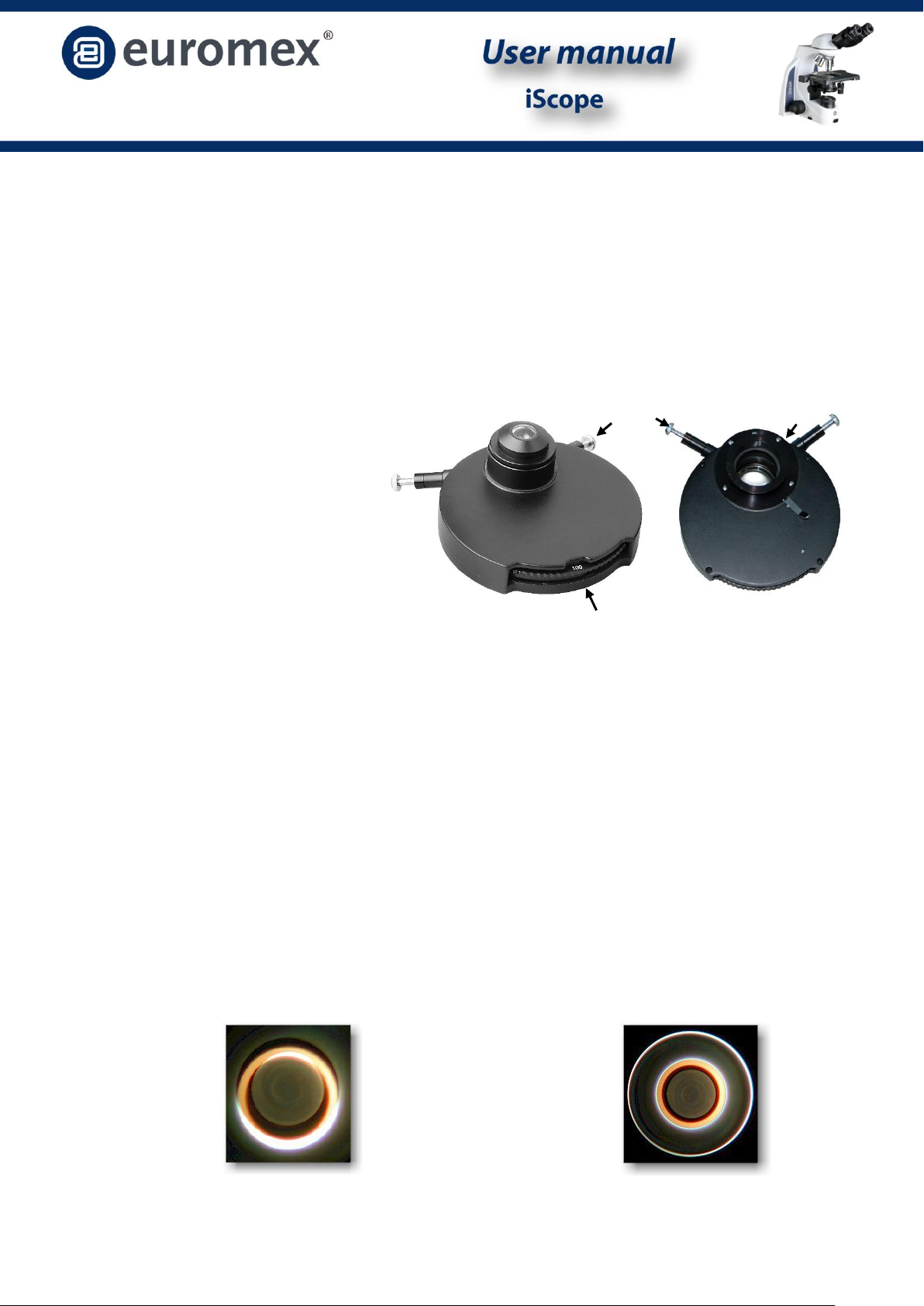
Centering the phase rings
The Zernike phase disc has five positions:
“DF” for dark field observation(upto 400x)
“BF” for bright field observation, this
position also has an irisdiafragm.
And
“10/20”
“40”
“100”
Which are corresponding to phase contrast observation using 10×、20×、40×、100×objectives
respectively.
When the condenser is in the DF or BF position the objectives can be used for either dark field or bright
field. For phase contrast, the condenser position should match the objective used. Meaning that when the
condenser is in position “40” the objective used should also be 40x.
Rotate 10× infinity plan phase contrast objective into the field of view, then set the condenser to match the
objective (marker “10/20”).
Take the eyepiece out of the tube and insert centering telescope in its place. Observed from centering
telescope, the dark and bright ring images should coincide with each other as shown in the figures below. If
the ring images can’t be observed clearly, first try and focus the centering telescope. If this does not solve
the issue raise or decline the condenser
If the bright ring and dark ring images are not coincided as shown below, adjust the position of the ring
with the two screw keys on the side of the condenser to move the ring until bright and dark ring images
superimposed. Repeat for all objectives/Zernike disc positions.
Not centered Centered properly
Zernike condensor postion indication bottom view of condensor
Centration screw keys iiris diafragm

Page 14
Maintenance and cleaning
Always place the dustcover over your iScope microscope after use. Keep the eyepiece and
objectives always mounted on the microscope to avoid dust entering the instrument.
Cleaning the optics
When the eyepiece lens or front lens of the 10x or S40x objective are dirty they can be cleaned by wiping a
piece of lens paper over the surface (circular movements). When this does not help put a drop of alcohol on
the lens paper. Never put xylol or alcohol directly on the lens! Please note that Euromex offers a special
microscope cleaning kit: PB.5275
It is not necessary –and not recommended –to clean the lens surfaces at the inner side of the objectives.
Sometimes dust can be removed with high pressured air. There will never be dust in the objectives if the
objectives are not removed from the revolving nosepiece.
Caution
Cleaning cloths containing plastic fibers can damage the coating of the lenses!
Maintenance of the stand
Dust can be removed with a brush. In case the stand or table is really dirty the surface can be
cleaned with a non-aggressive cleaning product.
All moving parts like the height adjustment or the coaxial course and fine adjustment contain ball
bearings that are not dust sensitive. With a drop of sewing-machine oil the bearing can be
lubricated.

Page 15
Replacing the fuse
To change the fuse, following the procedure below:
1. Unplug the system from power and place microscope flat, with base of microscope toward
you.
2. Find the fuse cover that will appear as a round protrusion with a slot.
3. Use a small flathead screwdriver or other flat object (coin, etc) to gently push the fuse
cover in and turn the cover counter clockwise. You need to turn the cover about 3/4 of a
turn.
4. The fuse cover will pop out with the fuse attached.
5. Remove the fuse from the cover and examine the fuse. If the thin piece of metal going
from one end of the fuse to the other has a gap, then the fuse is bad.
6. If the fuse is bad, install a replacement fuse in the cover.
7. Gently push the fuse cover with the new fuse back into the sub-woofer until it is flush with
the unit. Turn the cover clockwise about 3/4 to secure the cover back into the unit.
Note: Fuse may blow in order to protect internal damage to the microscope. And in most cases, replacing the fuse with the correct
voltage will resolve the issue. However, should you encounter a blown fuse frequently, please contact your distributor for further
assistance.
fuse specification: 250V, 150 mA

Page 16
Digital cameras
Digital cameras are designed to be used on the photo port of the microscope head. It is also
possible to use the digital camera in combination with a binocular head. For infinity type iScopes,
simple remove the eyepiece[1] and place the 30mm adapter ring into the eyepiece tube[2] then
place the camera with mounted c-mount adapter the eyepiece tube[3]. Focus the digital image
with the coarse and fine controls of the microscope. For finite(160mm) iScopes the procedure is
the same but there is no need to use an eyepiece tube[2].
For trinocular models, slide the camera with mounted c-mount adapter into the 23,2mm tube of
the phote port. For focussing slowly unscrew the tube (A) you will be able to match parfocality of
the camera with the view through the eyepieces by moving the camera up and down inside the
23,2mm tube. Take an easy-to-view specimen and focus the image through the microscope’s
eyepieces (with dioptre adjustment set on “0”). Afterwards, perform the height adjustment
procedure above while watching the image on the computer screen. In this case, once you have
obtained parfocality in the device, tighten screw (A) again. Screw (B) is only used to fix the
23,2mm tube on the iScope’s photo port.
Follow the manual that comes with the camera for camera operation.
Trinocular iScope head with camera in photo port Binocular iScope infinity type head with camera replacing the original eyepiece

Page 17
Accessories and spare parts
IS.6010 EWF 10x/20 mm eyepiece
IS.6011 EWF 10x/22 mm eyepiece
IS.6099 Pair of eye cups for iScope models
IS.7104 E-plan EPL 4x/0.10 objective
IS.7110 E-plan EPL 10x/0.25 objective
IS.7110 E-plan EPL 20x/0.40 objective
IS.7140 E-plan EPL S40x/0.65 objective
IS.716 E-plan EPL S60x/0.85 objective
IS.7100 E-plan EPL S100x/1.25 objective
IS.8804 E-plan EPLi 4x/0.10 IOS objective, infinity corrected
IS.8810 E-plan EPLi 10x/0.25 IOS objective, infinity corrected
IS.8820 E-plan EPLi 20x/0.40 IOS objective, infinity corrected
IS.8840 E-plan EPLi S40x/0.65 IOS objective, infinity corrected
IS.8800 E-plan EPLi S100x/1.25 IOS objective, infinity corrected
IS.7204 Plan PLi 4x/0.10 IOS objective, infinity corrected
IS.7210 Plan PLi 10x/0.25 IOS objective, infinity corrected
IS.7210 Plan PLi 20x/0.25 IOS objective, infinity corrected
IS.7240 Plan PLi S40x/0.65 IOS objective, infinity corrected
IS.7260 Plan PLi S60x/0.85 IOS objective, infinity corrected
IS.7200 Plan PLi S100x/1.25 IOS objective, infinity corrected
IS.7710 Plan Phase PLPH 10x/0.25 objective
IS.7720 Plan Phase PLPH 20x/0.40 objective
IS.7740 Plan Phase PLPH S40x/0.65 objective
IS.7700 Plan Phase PLPH S100x/1.25 objective
IS.8910 Plan Phase PLPHi 10x/0.25 IOS objective, infinity corrected
IS.8920 Plan Phase PLPHi 20x/0.40 IOS objective, infinity corrected
IS.8940 Plan Phase PLPHi S40x/0.65 IOS objective, infinity corrected
IS.8900 Plan Phase PLPHi S100x/1.25 IOS objective, infinity corrected
PB.5155 Microscope 76 x 26 mm glass slides, edges grinded, packed per 50 pieces
PB.5168 Cover glasses 22 x 22 mm, thickness 0.13-0.17 mm, packed per 100 pieces
PB.5255 Immersion oil n=1.482, 25 ml
PB.5274 Isopropanol 99%, 200 ml cleaning liquid
PB.5245 Lens cleaning paper, 100 sheets
More products can be found on our website.

Page 18
IS EN V4
This manual suits for next models
10
Table of contents
Other Euromex Microscope manuals


Popular Microscope manuals by other brands

3B SCIENTIFIC PHYSICS
3B SCIENTIFIC PHYSICS 1013373 instruction manual

Leica Microsystems
Leica Microsystems S 6 Series manual

Zeizz
Zeizz SteREO Discovery.V12 Brief instructions for use

STEINDORFF
STEINDORFF NYMCS-931 instruction manual

Bresser
Bresser National Geographic 9119100 operating instructions

JC LAB
JC LAB BIMC-12A user manual


