Euronda Euroseal User manual


Aquafilter+
TheEuroseal_Ing_rev02 - 17/11/14
1
Euroseal
®
Dear Doctor,
Thank you for the faith that you have shown us by acquiring our thermosealing machine Euroseal®.
We want you to know that our firm is at your complete disposition to furnish information and to answer any
questions concerning the operation and use of this equipment.
We remind you that for the correct usage of this machine it is necessary to first read this manual. The
Euroseal®corresponds to all of the relative safety regulations and presents no danger to the operator when
used according to the instructions. Please also note that Euronda S.p.A. declines all liability for incorrect or
insufficient interpretations of the translations of this manual: in the event of a dispute, only the manual written
in the Italian language shall apply.
While wishing you success in your work, we remind you that the reproduction of this manual is forbidden and
that the technical components could be changed without warning due to our continued technical research.
EURONDA S.p.A.

Aquafilter+
TheEuroseal_Ing_rev02 - 17/11/14
2
Euroseal
®
INDEX
INTRODUCTION...............................................................................................................................................3
GENERAL NOTES ON DELIVERY ..............................................................................................................3
GENERAL WARNINGS ................................................................................................................................ 3
INTENDED USE ...........................................................................................................................................3
MEANING OF THE SYMBOLS..................................................................................................................... 4
INFORMATION ABOUT THE WARRANTY..................................................................................................5
CHAPTER 1 ......................................................................................................................................................6
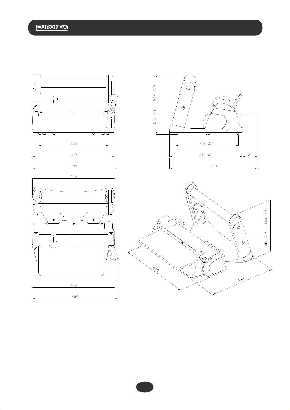
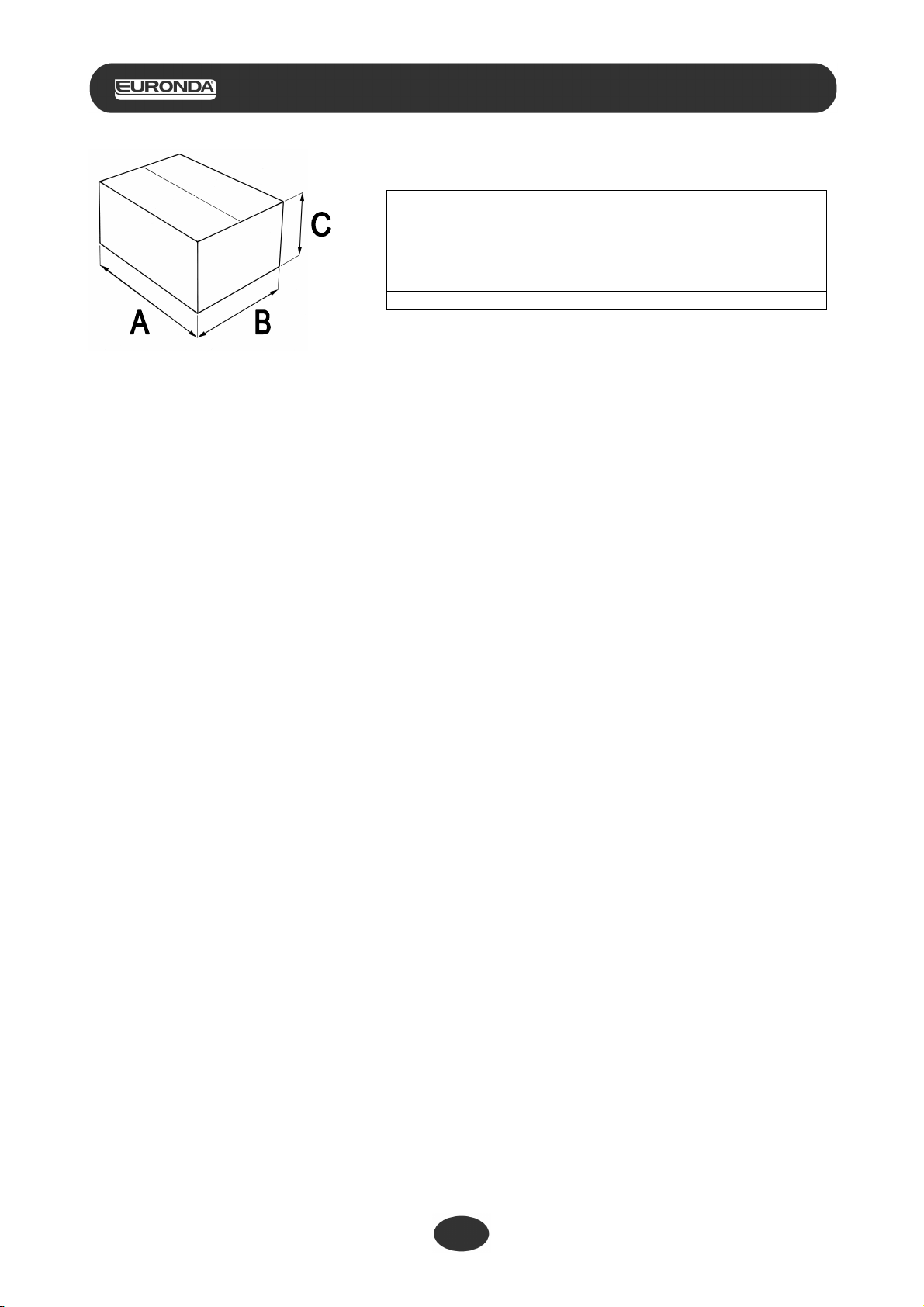
1.1 - OVERALL DIMENSIONS OF THE MACHINE AND ITS PACKAGING ................................................6
1.2 - DESCRIPTION OF THE CONTENTS ..................................................................................................8
CHAPTER 2 ......................................................................................................................................................9
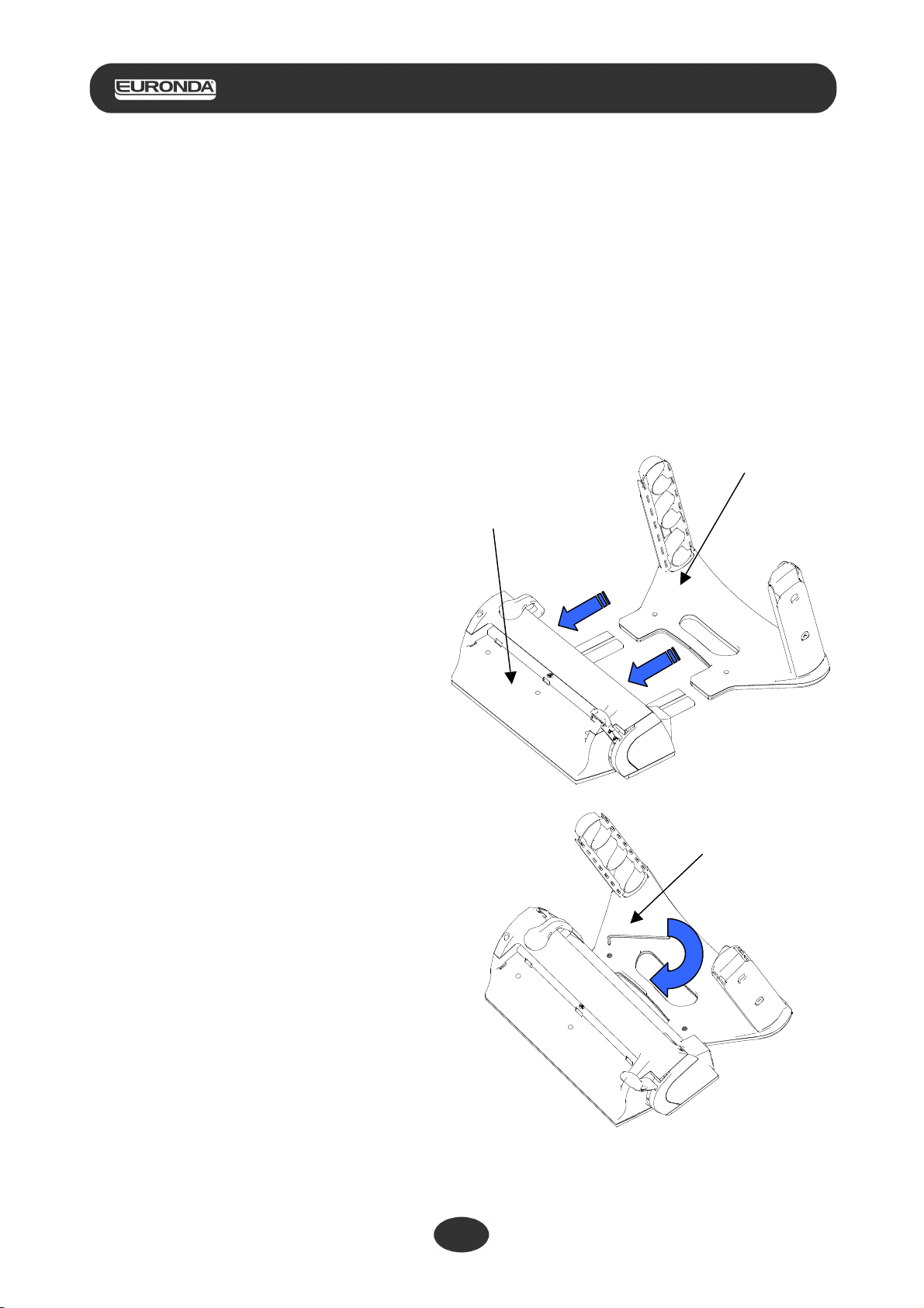
2.1 - INSTALLATION ....................................................................................................................................9
2.2 - ADJUSTMENT OF THE HEIGHT OF THE ROLL-HOLDER .............................................................. 11
2.3 - ISTRUCTIONS FOR WALL MOUNTING............................................................................................12
2.4 - SAFETY ..............................................................................................................................................14
2.5 - ELECTRIC CONNECTION ................................................................................................................. 15
CHAPTER 3 ....................................................................................................................................................16
3.1 - TECHNICAL SPECIFICATIONS.........................................................................................................16
CHAPTER 4 ....................................................................................................................................................17
4.1 - ISTRUCTIONS FOR USE................................................................................................................... 17
4.2 - ROLL-HOLDER GUIDE ...................................................................................................................... 19
CHAPTER 5 ....................................................................................................................................................20
5.1 - CLEANING THE THERMOSEALING DEVICE...................................................................................20
5.2 - EXTRAORDINARY MAINTENANCE..................................................................................................20
5.3 - TROUBLE SHOOTING.......................................................................................................................21
CHAPTER 6 ....................................................................................................................................................21
6.1 - INSTRUCTIONS FOR DISPOSAL ..................................................................................................... 21

Aquafilter+
TheEuroseal_Ing_rev02 - 17/11/14
3
Euroseal
®
INTRODUCTION
GENERAL NOTES ON DELIVERY
Upon delivery of the equipment, check the condition of the package and keep it in case of future needs.
Open the package and check that:
•The contents correspond to the technical specifications;
•There is no evidence of any damage.
In the event of damage or missing items, inform the carrier, dental dealer or Euronda S.p.A. immediately
providing all the details.
The dimensions mentioned in this manual are subject to change without notice.
Drawings and any other documents delivered with the equipment belong to the company Euronda S.p.A.
who reserves all rights; they cannot be made available to third parties.
The reproduction, either total or in part, of the texts and the illustrations in this manual is forbidden.
Euronda S.p.A reserves the right to improve or to make modifications to the manual or device without giving
prior notice and without updating previous manuals.
GENERAL WARNINGS
The figures who deal with the device, from the points of view of both use and maintenance are described
below.
THE OPERATOR is the person who physically uses the device according to its intended use.
THE RESPONSIBLE AUTHORITY is the person or group responsible for the use and ordinary maintenance
of the device and the training of the operator. The responsible authority is legally responsible for the
installation, correct functioning and use of the device.
The manufacturer cannot be considered responsible for possible breakages, injury or the poor functioning of
the device if it has not been used correctly or not been adequately maintained.
This manual is an integral part of the product and must be kept close to the equipment for easy and quick
reference. This manual provides instructions for:
•The correct installation;
•Safe and efficient functioning of the equipment;
•Continuous and scheduled maintenance.
The device must be used according to the procedures in this manual and never for purposes other than those
intended.
The device is intended for professional use and only qualified people can use it.
INTENDED USE
EUROSEAL®: device for the sealing and cutting of paper/propylene sterilization rolls. The device
cannot be used with rolls made of other materials.

Aquafilter+
TheEuroseal_Ing_rev02 - 17/11/14
4
Euroseal
®
MEANING OF THE SYMBOLS
Safety symbols on the device:
SYMBOL
DESCRIPTION
WARNING: HOT SURFACE
The following symbols appear on the device’s sticker. Their meaning is explained in the following table.
SYMBOL
DESCRIPTION
SN
"SERIAL NUMBER"
The symbol must be accompanied by the manufacturer’s serial number. The serial number
must be next to the symbol.
"DATE OF MANUFACTURE"
The symbol must be accompanied by the year of manufacture. The year must be
expressed in 4 digits.
"WARNING, PLEASE REFER TO INSTRUCTIONS FOR USE."
This symbol that appears on the device means that the parts must be disposed of separately
and recycled.
Moreover, in this manual certain symbols are used next to a description, a note etc. These icons aim to
attract the attention of the reader to notes or explanations of particular importance. Their meaning is
explained below.
SYMBOL
DESCRIPTION
PARTICULARLY IMPORTANT SAFETY INFORMATION.
This symbol aims to attract the reader’s attention to essential facts for the safety of the
operator.
INFORMATION AND WARNINGS
This symbol draws attention to general indications and recommendations.

Aquafilter+
TheEuroseal_Ing_rev02 - 17/11/14
5
Euroseal
®
INFORMATION ABOUT THE WARRANTY
Euronda guarantees the quality of its equipment, if used in accordance with the instructions supplied in this
manual, and according to the conditions printed on the warranty certificate.
The warranty is valid from the date of purchase by the client and the details can be found by registering on
www.euronda.com/myeuronda
In the case of dispute, the date indicated on the purchase invoice, showing the serial number of the unit, will
be considered as valid.
NOTE: please retain the original packaging and use it each time the unit needs to be transported. The use of
different packaging could damage the product during transportation.

Aquafilter+
TheEuroseal_Ing_rev02 - 17/11/14
6
Euroseal
®
CHAPTER 1
1.1 - OVERALL DIMENSIONS OF THE MACHINE AND ITS PACKAGING
Overall dimensions of the thermosealing device

Aquafilter+
TheEuroseal_Ing_rev02 - 17/11/14
7
Euroseal
®
Dimensions of the package:
A = 520 mm
B = 400 mm
C = 365 mm
Total weight of the packaging: 8,5 kg

Aquafilter+
TheEuroseal_Ing_rev02 - 17/11/14
8
Euroseal
®
1.2 - DESCRIPTION OF THE CONTENTS
The packaging contains the following components:
Description
Quantity
Sealing & Cutting station
1
Roll-holder
1
Work surface
1
Roll-holder tubes
2
Roll-holder guide
4
Mains wire
1
Allen key
1
Spare fuses
2
Instruction manual
1
Quick-start guide
1
Warranty certificate
1
NOTE: it is recommended to keep the original packaging for use when transporting the device.
The use of other packaging could result in the damage of the product during transportation.

Aquafilter+
TheEuroseal_Ing_rev02 - 17/11/14
9
Euroseal
®
CHAPTER 2
2.1 - INSTALLATION
Install the product respecting the following warnings:
•Position the thermosealing device on a flat surface with sufficient working space around it.
•Do not install the machine next to sinks or anything similar in order to avoid contact with water and the
short circuit of the electrical system.
•Avoid proximity to sources of heat.
•Install the machine in an area with normal ventilation.
•Make sure that the mains wire is not bent and that it is free of obstruction up to the electric socket.
1) Remove the sealing/cutting station and the roll-holder with care from the packaging.
2) Insert the roll-holder into the sealing &
cutting station by sliding it along the steel
guides.
3) Push the roll-holder as far as it will go in
order to take up as little space as possible
or the distance can be adjusted according
to ones needs.
4) Tighten the two screws (1 and 2) with the
supplied allen key until they are fully
tightened.
Sealing & Cutting station
Roll-holder
Allen key
1
2

Aquafilter+
TheEuroseal_Ing_rev02 - 17/11/14
10
Euroseal
®
5) Insert one or two of the tubes* on the roll-
holder making sure that the tooth of the roll-
holder slots into the slit on the tube, if
necessary by turning the tube.
*according to the desired use.
(see paragraph 3.2)
6) Insert the work surface by inserting the 3
teeth into the relevant holes on the sealing
& cutting station (1) and lower the surface
so that it blocks onto the ledge (2).
7) Insert the mains wire.
The device is ready for use.
NOTE: The thermosealing device has been tested and calibrated in the factory.
Roll-holder tube
Work surface
1
2
Plug for the mains wire
Mains wire

Aquafilter+
TheEuroseal_Ing_rev02 - 17/11/14
11
Euroseal
®
2.2 - ADJUSTMENT OF THE HEIGHT OF THE ROLL-HOLDER
The thermosealing device can be used in several ways:
A – with the roll-holder lowered with one tube
B – with the roll-holder extended with one or two tubes
To extend the roll-holder when it is lowered:
1) Push the buttons on either side of the roll-
holder
2) Push both sides of the roll-holder upwards
until the buttons fit into the upper holes.
Note: remove the tube before carrying out this
operation.
To lower the roll-holder when it is extended:
1) Push the buttons on either side of the roll-
holder
2) Push both sides of the roll-holder downwards
until the buttons fit into the lower holes.
Note: remove the tube/s before carrying out this
operation.
WARNING:
When the roll-holder is fully extended, place the lighter rolls of pouches on the higher tube.
Load a maximum of 5 kg.
1
2
Button
2
1
Button

Aquafilter+
TheEuroseal_Ing_rev02 - 17/11/14
12
Euroseal
®
2.3 - ISTRUCTIONS FOR WALL MOUNTING
The thermosealing device has been designed to be used in several ways:
•sealing & cutting station on a flat surface
•sealing & cutting station on a flat surface, roll-holder on a
wall
When the roll-holder is on
the wall, the sealing &
cutting station takes up 325
mm, because there are the
steel runners.
To reduce the space
needed, the steel runners
can be removed using the
allen key to remove the
screws that hold the runners
in place.
The space required is then
only 210 mm (plus the mains
wire).

Aquafilter+
TheEuroseal_Ing_rev02 - 17/11/14
13
Euroseal
®
For wall-mounting the roll-holder, follow the instructions below.
1) Fix two dowel screws of diameter 6 (screw head:
max. diameter 9,5 mm, main part of screw: max
diameter of 5 mm) with a wheel base of 213 mm.
Leave a protrusion of 13mm between the screw
head and the wall so that the roll-holder can be
mounted.
Use dowel screws that are suitable for the type of wall (cement, brick, plasterboard etc.)
2) Attaching the roll-holder to the dowel-screws in
the wall.
Place the holes in the roll-holder onto the dowel-
screw heads (1) and pull downwards (2) to hold
it in place.
3) Insert the tube with the rolls (see 3.1 – Installation).
ATTENTION:
Insert the tube on the roll-holder making sure that the tooth of the roll holder slots into the slit on
the tube, turning the tube if necessary.
WARNING:
When the roll-holder is wall-mounted, it is suggested to use it fully lowered with only one tube
(see 3.2).
If the roll-holder is used fully extended with two tubes, place the lighter rolls on the outermost
tube. Load a maximum of 2 kg.
1
2

Aquafilter+
TheEuroseal_Ing_rev02 - 17/11/14
14
Euroseal
®
2.4 - SAFETY
Before using your thermosealing device, please read the following safety information carefully. Non
compliance could cause accidents or damage to the device.
WARNING:
Do not place fingers near the sealing area when the machine is turned on or after it has
been turned off.
If for any reason this area must be accessed, wait until the sealing area has cooled.
Do not insert your fingers under the sealing area’s protective lid when the sealing handle
has been lowered.
Never insert fingers in the cutting blade runner.
WARNING:
Keep the area near the thermosealing device clean and dry.
NEVER DISMANTLE THE THERMOSEALING DEVICE. THE INTERNAL VOLTAGES CAN BE
DANGEROUS.
If it is not possible to disconnect the electrical supply, switch off at the mains supply power
switch and if this is far away or not visible by those carrying out the maintenance, place a sign
saying “work in progress” on the switch after having set it to the “OFF” position.
Protective Lid
Cutting blade runner
Sealing area
Sealing area

Aquafilter+
TheEuroseal_Ing_rev02 - 17/11/14
15
Euroseal
®
WARNING:
Clean the thermosealing device with a damp cloth, after having made sure that the mains
wire has been disconnected (before re-using the thermosealing device, make sure that
there are no traces of humidity).
Do not use solvents on the sticker.
Make sure that the wiring is earthed according to the current norms in the country of
installation.
Do not remove the sticker on the thermosealing device.
Make sure that the device is powered with the correct voltage.
ONLY USE THE ORIGINAL MAINS WIRE PROVIDED.
ONLY USE ORIGINAL SPARE PARTS.
If the machine does not work properly, please refer to the “Trouble shooting” section in this manual to find the
possible causes. If you need further information or are in need of repairs, contact the dental dealer or the
specialised staff from your supplier or contact Euronda S.p.A’s technical office directly.
WARNING:
•The machine conforms to the electrical safety requisites of the Normative Institutions and is
supplied with a bipolar plug that assures the device is put to earth.
•It is essential to make sure that the electric system is properly put to earth and that the power
is suitable for the power of the device indicated on the product sticker. If in doubt, consult a
qualified electrician..
THE NON COMPLIANCE WITH WHAT IS WRITTEN ABOVE RELEASES EURONDA S.P.A. OF ALL
RESPONSIBILITY
2.5 - ELECTRIC CONNECTION
Check that the voltage indicated on the product label corresponds to that available in the place of installation.
The device must be connected using the original mains wire to a system sufficiently put to earth and in
conformity with the applicable norms in the country of installation.
WARNING:
Do not bend the wire or place objects of any kind on it.

Aquafilter+
TheEuroseal_Ing_rev02 - 17/11/14
16
Euroseal
®
CHAPTER 3
3.1 - TECHNICAL SPECIFICATIONS
Voltage
200 / 240 V
100 / 120 V
Number of phases
1
1
Power supply
50 / 60 Hz
50 / 60 Hz
Power
100 W
100 W
Isolation class
I / IPX0
I / IPX0
Fuses
Nr. 2 – 5x 20 T4 A
Nr. 2 – 5x 20 F10 A
Environmental conditions for which
the device has been designed
•Internal use
•Altitude up to 3000 m
•Temperature: +5 / +40 °C
•Relative max. humidity: 85%
•Max voltage variation: ± 10 %
•Installation category (overvoltage category): II
•Pollution level: 1
Interrupter
bipolar
Weight
7.1 Kg
Dimensions of the seal
12 x 310 mm
Type of sealing
At constant temperature

Aquafilter+
TheEuroseal_Ing_rev02 - 17/11/14
17
Euroseal
®
CHAPTER 4
4.1 - ISTRUCTIONS FOR USE
1) Make sure that the device is connected to the
electrical supply.
Press the power switch on the back of the
machine.
2) The led light on the front of the device begins
to flash orange whilst the device is heating up.
The led turns completely green when the
resistance has reached the ideal sealing
temperature.
The device is then ready to be used.
NOTE: if the sealing handle is pressed down during the heating up phase (flashing orange), the
led will turn red and an alarm will begin to sound so as to warn that the device is not ready to be
used. Lift up the handle and wait until the led becomes completely green.
3) Insert the roll under the roll stopper.
The pouch can be inserted with
the propylene film either above
or below.
However, when using gusseted
rolls the propylene film must
face UPWARDS.
Power switch
Led light
Roll stopper

Aquafilter+
TheEuroseal_Ing_rev02 - 17/11/14
18
Euroseal
®
When both roll-holder tubes are used
A: insert the rolls on the upper tube with the roll coming from underneath.
B: insert the rolls on the lower tube with the roll coming from above.
4) Pull the roll to the desired length and lower the
sealing handle. The led flashes green during the
sealing phase (for 3 seconds).
5) Slide the cutting handle to cut the roll to make
the bag (whilst the handle is down).
At the end of the sealing phase, the led becomes
completely green and there is an acoustic signal
to inform the user.
At this point the sealing is complete.
6) Lift up the sealing handle.
The led goes back to being completely green
and the acoustic signal stops.
Pull out the pouch.
The device is ready for the next sealing
operation without having to wait for it to cool.

Aquafilter+
TheEuroseal_Ing_rev02 - 17/11/14
19
Euroseal
®
WARNING:
if the operator does not lift the sealing handle after sealing, the resistor automatically turns itself
off so as not to burn the bag.
In this situation the led flashes orange and the alarm sounds intermittently.
As soon as the handle is lifted, the resistor turns itself back on automatically. It takes a few
seconds for the ideal temperature to be achieved so as to be able to re-start sealing.
4.2 - ROLL-HOLDER GUIDE
Using the roll holder guide
The roll-holder guides provided prevent the paper from falling irregularly out the sides during its unrolling
from the roll.
Proceed as follows:
1) insert the roll-holder guide on the roll holder tube by
applying slight pressure to snap it into place.
2) Push the roll-holder guide closer inwards until it
holds the paper in place.
Table of contents
Other Euronda Food Saver manuals