EURONORM JI150 User manual

www.euronormdrives.com info@euronorm.nl +31 (0) 252 228850
Frequency Drive
JI150
Manual

Hub van Doorneweg 8 • 2171 KZ Sassenheim – NL • T+31(0)252 228850 • F+31(0)252 228235 • E[email protected] • Ieuronormdrives.com
2 3
EURN010000_002_C
EURN010000_002_C
Inhoud
1. Foreword 3
2. Instructions on nameplate 3
3. Dimension 4
4. Operation keyboard introduction 5
4.1 Keyboard indicator 5
4.2 Operation panel button description 5
5. Standard specifications 6
6. Wiring diagram 8
7. Parameter list 9
d0 group Monitoring function group 9
F0 group Basic Functional Parameter Group 10
F1 group Input terminals 11
F2 group Output terminal 13
F3 group Start and stop control group 14
F4 group V/F control parameter group 15
F5 group Vector control parameter group 15
F6 group Keyboard and display 16
F7 group Auxiliary function parameter group 17
F8 group Fault and protection parameter group 18
F9 group Communication parameter group 18
Fb group Control parameter optimization group 19
E0 group Wobbulate, fixed-length and counting group 19
E1 group Multi-speed, sample PLC parameter 20
E2 group PIDfunction parameter group 21
b0 group Motor parameters 22
y0 group Function code management 22
y1 group Fault query parameter group 23
8. Fault alarm and countermeasures 24

Hub van Doorneweg 8 • 2171 KZ Sassenheim – NL • T+31(0)252 228850 • F+31(0)252 228235 • Esales@euronorm.nl • Ieuronormdrives.com
Hub van Doorneweg 8 • 2171 KZ Sassenheim – NL • T+31(0)252 228850 • F+31(0)252 228235 • E[email protected] • Ieuronormdrives.com
2 3
EURN010000_002_C
EURN010000_002_C
1. Foreword
Thank you for choosing JI150 series fundamental form frequency inverter.
The diagrams of these operating instructions are used for convenience of explanation and may be slightly different from
the product due to product upgrades.
Please take this manual to the end user and keep it for future maintenance use.
If you have any questions, please get in touch with our company or our agent in time, we will offer dedicated service to
you.
2. Instructions on nameplate
Hub van Doorneweg 8 • 2171 KZ Sassenheim – NL • T+31(0)252 228850 • F+31(0)252 228235 • E[email protected] • Ieuronormdrives.com
4 5
EURN010000_002_C
EURN010000_002_C
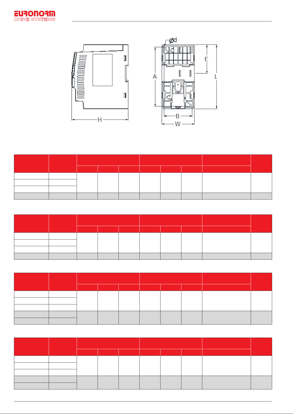
3. Dimension
4 / 24
33..DDiimmeennssiioonn
0.75~5.5kW G3 support rail mounting
Outline dimension drawing and installation dimension of single phase 220 V AC
Model Output power
(kW)
Dimension
(mm) Installation (mm)
Guide rail
installation
position (mm)
Weight
(kg)
L
W
H
A
B
d
E
JI150 0R4G1(Z)
0.4
138 72 123.5 127 61 5 62 1.1
JI150 0R7G1(Z)
0.75
JI150 1R5G1(Z)
1.5
JI150 2R2G1(Z)
2.2
185
72
134
175
45
5
82
1.3
Dimensions and installation size of three-phase 220V AC
Model Output power
(kW)
Dimension
(mm) Installation (mm)
Guide rail
installation position
(mm)
Weight
(kg)
L
W
H
A
B
d
E
JI150 0R4G2(Z)
0.4
138 72 123.5 127 61 5 62 1.1
JI150 0R7G2(Z)
0.75
JI150 1R5G2(Z)
1.5
JI150 2R2G2(Z)
2.2
185
72
134
175
45
5
82
1.3
Dimensions and installation size of three-phase 380V AC
Model Output power
(kW)
Dimension
(mm) Installation (mm)
Guide rail
installation position
(mm)
Weight
(kg)
L
W
H
A
B
d
E
JI150 0R7G3(Z)
0.75
138 72 123.5 127 61 5 62 1.1
JI150 1R5G3(Z)
1.5
JI150 2R2G3(Z)
2.2
JI150 004G3(Z)
4
185 72 134 175 45 5 82 1.3
JI150 5R5G3(Z)
5.5
Dimensions and installation size of three-phase 480V AC
Model Output power
(kW)
Dimension
(mm) Installation (mm)
Guide rail
installation position
(mm)
Weight
(kg)
L
W
H
A
B
d
E
JI150 0R7G4(Z)
0.75
138 72 123.5 127 61 5 62 1.1
JI150 1R5G4(Z)
1.5
JI150 2R2G4(Z)
2.2
JI150 004G4(Z)
4
185 72 134 175 45 5 82 1.3
JI150 5R5G4(Z)
5.5
0.75~5.5kW G3 support rail mounting
Outline dimension drawing and installation dimension of single phase 220 V AC
Model
Output
power
(kW)
Dimension
(mm) Installation (mm) Guide rail installation
position (mm) Weight
(kg)
L W H A B d E
JI150 0R4G1(Z) 0.4
138 72 123.5 127 61 5 62 1.1JI150 0R7G1(Z) 0.75
JI150 1R5G1(Z) 1.5
JI150 2R2G1(Z) 2.2 185 72 134 175 45 5 82 1.3
Dimensions and installation size of three-phase 220V AC
Model
Output
power
(kW)
Dimension
(mm) Installation (mm) Guide rail installation
position (mm) Weight
(kg)
L W H A B d E
JI150 0R4G2(Z) 0.4
138 72 123.5 127 61 5 62 1.1JI150 0R7G2(Z) 0.75
JI150 1R5G2(Z) 1.5
JI150 2R2G2(Z) 2.2 185 72 134 175 45 5 82 1.3
Dimensions and installation size of three-phase 380V AC
Model
Output
power
(kW)
Dimension
(mm) Installation (mm) Guide rail installation
position (mm) Weight
(kg)
L W H A B d E
JI150 0R7G3(Z) 0.75
138 72 123.5 127 61 5 62 1.1JI150 1R5G3(Z) 1.5
JI150 2R2G3(Z) 2.2
JI150 004G3(Z) 4 185 72 134 175 45 5 82 1.3
JI150 5R5G3(Z) 5.5
Dimensions and installation size of three-phase 480V AC
Model
Output
power
(kW)
Dimension
(mm) Installation (mm) Guide rail installation
position (mm) Weight
(kg)
L W H A B d E
JI150 0R7G4(Z) 0.75
138 72 123.5 127 61 5 62 1.1JI150 1R5G4(Z) 1.5
JI150 2R2G4(Z) 2.2
JI150 004G4(Z) 4 185 72 134 175 45 5 82 1.3
JI150 5R5G4(Z) 5.5

Hub van Doorneweg 8 • 2171 KZ Sassenheim – NL • T+31(0)252 228850 • F+31(0)252 228235 • Esales@euronorm.nl • Ieuronormdrives.com
Hub van Doorneweg 8 • 2171 KZ Sassenheim – NL • T+31(0)252 228850 • F+31(0)252 228235 • E[email protected] • Ieuronormdrives.com
4 5
EURN010000_002_C
EURN010000_002_C
4. Operation keyboard introduction
4.1 Keyboard indicator
Indicator light Name
5 / 24
44..OOppeerraattiioonnkkeeyybbooaarrddiinnttrroodduuccttiioonn
4.1 Keyboard indicator
Indicator light
Name
Status light
RUN
Running indicator light
* ON: The inverter is working
* OFF: The inverter stops
FWD/REV
Forward/reverse running light
* ON: In forward status
* OFF: In reversal status
Hz
Frequency indicator
A
Current indicator
4.2 Operation panel button description
Sign
Name
Function
Parameter setting/esc key
* Enter into the modified status of main menu;
* Esc from functional parameter modification;
* Esc submenu or functional menu to status menu
Shift Key *Choose displayed parameter circularly under running or stop interface; choose parameter’s modified
position when modify parameter
Increasing key * Parameter or function number increasing
Decreasing key * Parameter or function number decreasing
Running key * For starting running in the mode of keyboard control status
Stop/Reset key * For stopping running in the running status; for resetting the operation in fault alarm status. The
function of the key is subject to F6.00
Enter key * Step by step into the menu screen, set parameters to confirm.
Quick multi-function key * This key function is determined by the function code F6.21
55..SSttaannddaarrddssppeecciiffiiccaattiioonnss
Items
Specifications
Power
Input
Rated voltage
AC 1PH 220V(-15%)
~
240V(+10%)
AC 3PH 220V(-15%)~240V(+10%)
AC 3PH 380V(-15%)~440V(+10%)
AC 3PH 480V(-10%)~480V(+10%)
Input frequency
50Hz/60Hz
Allowing fluctuations
Voltage continued volatility:±10%
Less than 3% of voltage unbalance rate 3%;
Input frequency fluctuation:±5%;
Distortion satisfy IEC61800-2 standard
Control system
Control system
High performance vector control inverter based on DSP
Control method
V/F control, vector control W/O PG
Automatic torque boost function
Realize low frequency (1Hz) and large output torque control under the V/F control mode.
Acceleration/deceleration control
Straight or S-curve mode. Four times available and time range is 0.0~6500.0s.
V/F curve mode
Linear, square root/m-th power, custom V/F curve
Over load capability
G type:Rated current 150% - 1 minute, rated current 180% - 2 seconds
Maximum frequency
1. Vector control:0~300Hz; 2. V/F control:0~3200Hz
Carrier frequency
0.5~16kHz; automatically adjust carrier frequency according to the load characteristics.
Input frequency resolution
Digital setting:0.01Hz minimum analog:Maximum frequency*0.025%.
Start torque
G type: 0.5Hz/150% (Vector control W/O PG)
Speed range
1:100 (Vector control W/O PG)
Steady-speed precision
Vector control W/O PG: ≤± 0.5% (Rated synchronous speed)
Torque response
≤ 40ms (Vector control W/O PG)
Torque boost
Automatic torque boost; manual torque boost(0.1%~30.0%)
Status light
RUN
Running indicator light
* ON: The inverter is working
* OFF: The inverter stops
FWD/REV
Forward/reverse running light
* ON: In forward status
* OFF: In reversal status
Hz Frequency indicator
A Current indicator
4.2 Operation panel button description
Sign Name Function
Parameter setting/esc key
* Enter into the modified status of main menu;
* Esc from functional parameter modification;
* Esc submenu or functional menu to status menu
Shift Key *Choose displayed parameter circularly under running or stop interface; choose parameter’s modified position
when modify parameter
Increasing key * Parameter or function number increasing
Decreasing key * Parameter or function number decreasing
Running key * For starting running in the mode of keyboard control status
Stop/Reset key * For stopping running in the running status; for resetting the operation in fault alarm status. The function of the
key is subject to F6.00
Enter key * Step by step into the menu screen, set parameters to confirm.
Quick multi-function key * This key function is determined by the function code F6.21

Hub van Doorneweg 8 • 2171 KZ Sassenheim – NL • T+31(0)252 228850 • F+31(0)252 228235 • E[email protected] • Ieuronormdrives.com
6 7
EURN010000_002_C
EURN010000_002_C
5. Standard specifications
Items Specifications
Power Input
Rated voltage
AC 1PH 220V(-15%)~240V(+10%)
AC 3PH 220V(-15%)~240V(+10%)
AC 3PH 380V(-15%)~440V(+10%)
AC 3PH 480V(-10%)~480V(+10%)
Input frequency 50Hz/60Hz
Allowing fluctuations
fluctuation:±5%;
Voltage continued volatility:±10% Less than 3% of voltage unbalance rate 3%;
Input frequency Distortion satisfy IEC61800-2 standard
Control system
Control system High performance vector control inverter based on DSP
Control method V/F control, vector control W/O PG
Automatic torque boost
function Realize low frequency (1Hz) and large output torque control under the V/F control mode.
Acceleration/deceleration
control Straight or S-curve mode. Four times available and time range is 0.0~6500.0s.
V/F curve mode Linear, square root/m-th power, custom V/F curve
Over load capability G type:Rated current 150% - 1 minute, rated current 180% - 2 seconds
Maximum frequency 1. Vector control:0~300Hz; 2. V/F control:0~3200Hz
Carrier frequency 0.5~16kHz; automatically adjust carrier frequency according to the load characteristics.
Input frequency resolution Digital setting:0.01Hz minimum analog:Maximum frequency*0.025%.
Start torque G type: 0.5Hz/150% (Vector control W/O PG)
Speed range 1:100 (Vector control W/O PG)
Steady-speed precision Vector control W/O PG: ≤± 0.5% (Rated synchronous speed)
Torque response ≤ 40ms (Vector control W/O PG)
Torque boost Automatic torque boost; manual torque boost(0.1%~30.0%)
DC braking The built-in PID adjusts the braking current to ensure sufficient braking torque without over-flow.DC braking
frequency: 0.0Hz to max. frequency, braking time:0.0~100.0 seconds, braking current value: 0.0%~100.0%
Jogging control Jog frequency range: 0.00Hz to max. frequency; jog Ac/deceleration time: 0.0~6500.0s.
Built-in PID Easy to realize closed-loop control system for the process control.
Automatic voltage
regulation(AVR) Automatically maintain a constant output voltage when the voltage of electricity grid changes.
Speed tracking method Automatically track current motor speed when the inverter starts
Personalization
function
Self-inspection of peripherals
after power-on After powering on, peripheral equipment will perform safety testing, such as ground, short circuit, etc.
Quick current limiting The current limiting algorithm is used to reduce the inverter over current probability, and improve whole unit
anti-interference capability.
Timing control Timing control function: Time setting range(0m~6500m)
Running
Input Signal
DI Input terminal 5 digital input terminals
AI1 analog input 1 analog AI1 input terminal, select 0~10V or 0~20mA input
Multi-speed At most 16-speed can be set(Run by using the multi-function terminals or program)
Emergency stop Interrupt controller output
Fault reset When the protection function is active, you can automatically or manually reset the fault condition.
PID feedback signal Including DC(0~10V), DC(0~20mA)
Output Signal
Output terminal 1 way relay output terminal; 1 way DA1 analog output terminal
Relay output There are 40 kinds of signals to choose from each way. Contact capacity of the relay: Normally open contact
5A/AC 250V; 5A/DC 30V
DA1 analog output 1 way analog output, you can select 16 kinds of signals such as frequency, current, voltage, etc. The output
signal range can be set arbitrarily within 0~10V/0~20mA.
Running command channel Three channels: Operation panel, control terminals and serial communication port. They can be switched
through a variety of ways.
Frequency source Total 7 frequency sources: Digital, analog voltage, multi-speed, and serial port.
Run function Limit frequency, jump frequency, frequency compensation, auto-tuning, PID control

Hub van Doorneweg 8 • 2171 KZ Sassenheim – NL • T+31(0)252 228850 • F+31(0)252 228235 • Esales@euronorm.nl • Ieuronormdrives.com
Hub van Doorneweg 8 • 2171 KZ Sassenheim – NL • T+31(0)252 228850 • F+31(0)252 228235 • E[email protected] • Ieuronormdrives.com
6 7
EURN010000_002_C
EURN010000_002_C
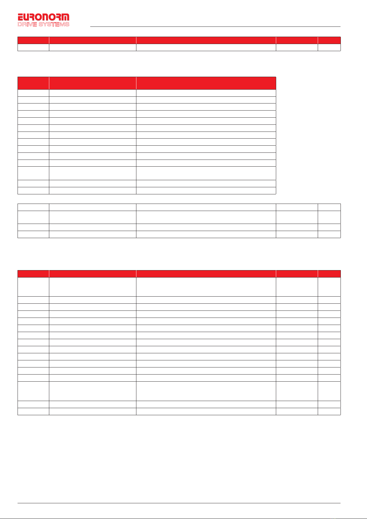
Items Specifications
Protection function
Inverter protection
Overvoltage protection, undervoltage protection, overcurrent protection, overload protection, overheat
protection, overcurrent stall protection, overvoltage stall protection, losting-phase protection (Optional),
communication error, PID feedback signal abnormalities, and short circuit to ground protection.
Display
LED display
keyboard
Running
information
Monitoring objects including: Running frequency, set frequency, bus voltage, output voltage, output current,
output power, output torque, input terminal status, output terminal status, analog AI1 value , motor Actual
running speed ,PID set value percentage, PID feedback value percentage.
Error
information
At most save three error message, and the time, type, voltage, current, frequency and work status can be
queried when the failure is occurred.
Key lock and function
selection Lock part or all of keys, define the function scope of some keys to prevent misuse.
IGBT temperature Display current IGBT temperature inside the inverter.
Communication
RS485 Built-in 485
Environment
Environment temperature -10~40℃(The environment temperature in 40~50 ℃, please derating use)
Storage temperature -20~65 ℃
Environment humidity Less than 90% R.H, no condensation.
Vibration Below 5.9m/s² (= 0.6g)
Application sites Indoor where no sunlight or corrosive, explosive gas and water vapor, dust, flammable gas, oil mist, water
vapor, drip or salt, etc.
Altitude Use below 1000m without derating, 1% for each 100m increasing above 1000m, the highest altitude is 3000m
Protection level IP20
Product
standard
Product adopts safety
standards. IEC61800-5-1:2007
Product adopts EMC
standards. IEC61800-3:2005
Cooling method Forced air cooling
Installation method Rail mounting, wall mounting
Hub van Doorneweg 8 • 2171 KZ Sassenheim – NL • T+31(0)252 228850 • F+31(0)252 228235 • E[email protected] • Ieuronormdrives.com
8 9
EURN010000_002_C
EURN010000_002_C
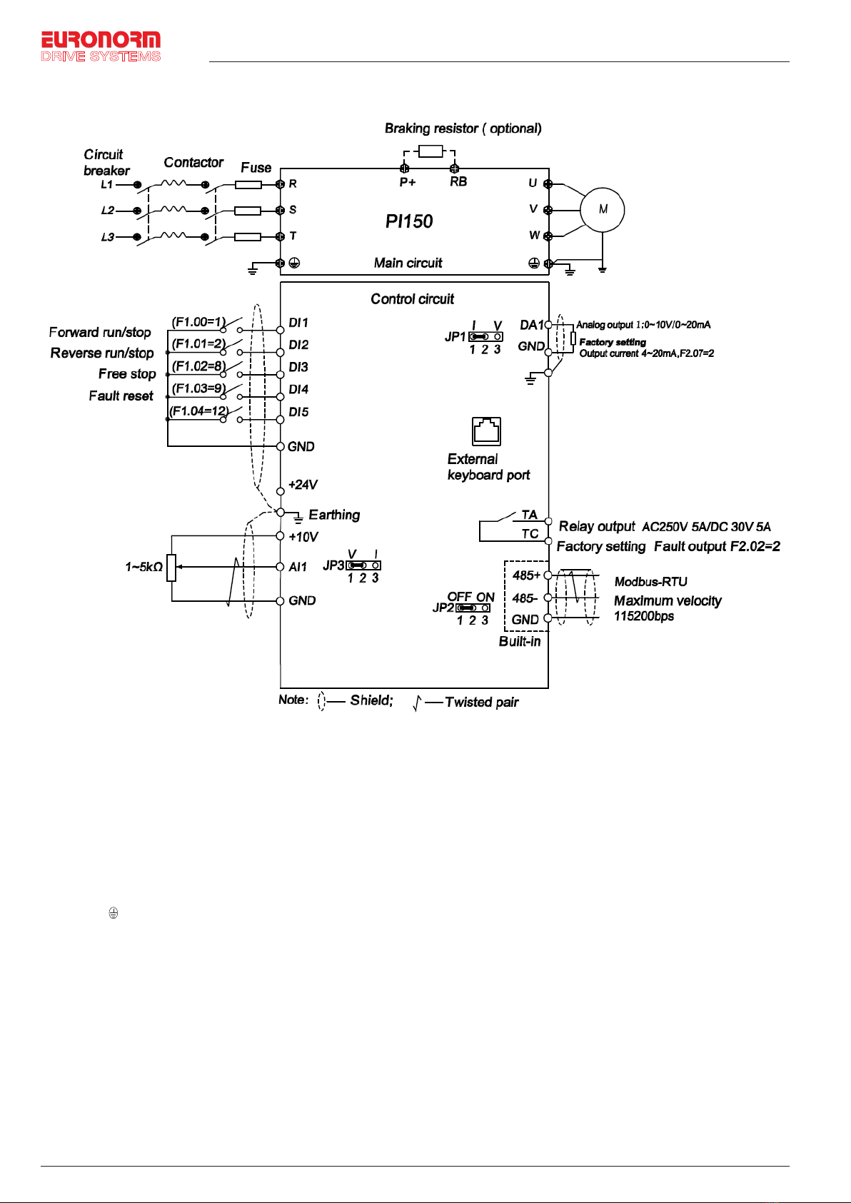
6. Wiring diagram
8 / 24
66..WWiirriinnggddiiaaggrraamm
Notes in main circuit wiring
Wiring specifications, please implement wiring in accordance with electrical regulations;
Do not connect AC to the output of frequency converter (U, V, W), otherwise the frequency inverter will be damaged;
Power supply wiring, please try to use isolation line and pipeline, and the isolation line or pipeline ends grounded;
Frequency inverter grounding wire cannot be grounded together with welding machine, high-power motor or high current load, please grounding alone;
Grounding please grounding correctly,grounding resistor less than 10Ω.
Notes in wiring control circuit
Please separate the control signal line from the main circuit line and other power lines;
To prevent misoperation caused by interference, use twisted or double shielded wires,specification 0.5~2mm²;
Make sure the permissible conditions of each terminal, such as power supply, maximum permissible current, etc;
The terminal wiring requirements, correct selection of accessories, such as: Voltmeter, input power supply, etc;
After completing the wiring, please check it correctly and make sure that it is correct before powering it on.
Notes in main circuit wiring
Wiring specifications, please implement wiring in accordance with electrical regulations;
Do not connect AC to the output of frequency converter (U, V, W), otherwise the frequency inverter will be damaged;
Power supply wiring, please try to use isolation line and pipeline, and the isolation line or pipeline ends grounded;
Frequency inverter grounding wire cannot be grounded together with welding machine, high-power motor or high current
load, please grounding alone;
Grounding please grounding correctly,grounding resistor less than 10Ω.
Notes in wiring control circuit
Please separate the control signal line from the main circuit line and other power lines;
To prevent misoperation caused by interference, use twisted or double shielded wires,specification 0.5~2mm²;
Make sure the permissible conditions of each terminal, such as power supply, maximum permissible current, etc;
The terminal wiring requirements, correct selection of accessories, such as: Voltmeter, input power supply, etc;
After completing the wiring, please check it correctly and make sure that it is correct before powering it on.

Hub van Doorneweg 8 • 2171 KZ Sassenheim – NL • T+31(0)252 228850 • F+31(0)252 228235 • Esales@euronorm.nl • Ieuronormdrives.com
Hub van Doorneweg 8 • 2171 KZ Sassenheim – NL • T+31(0)252 228850 • F+31(0)252 228235 • E[email protected] • Ieuronormdrives.com
8 9
EURN010000_002_C
EURN010000_002_C
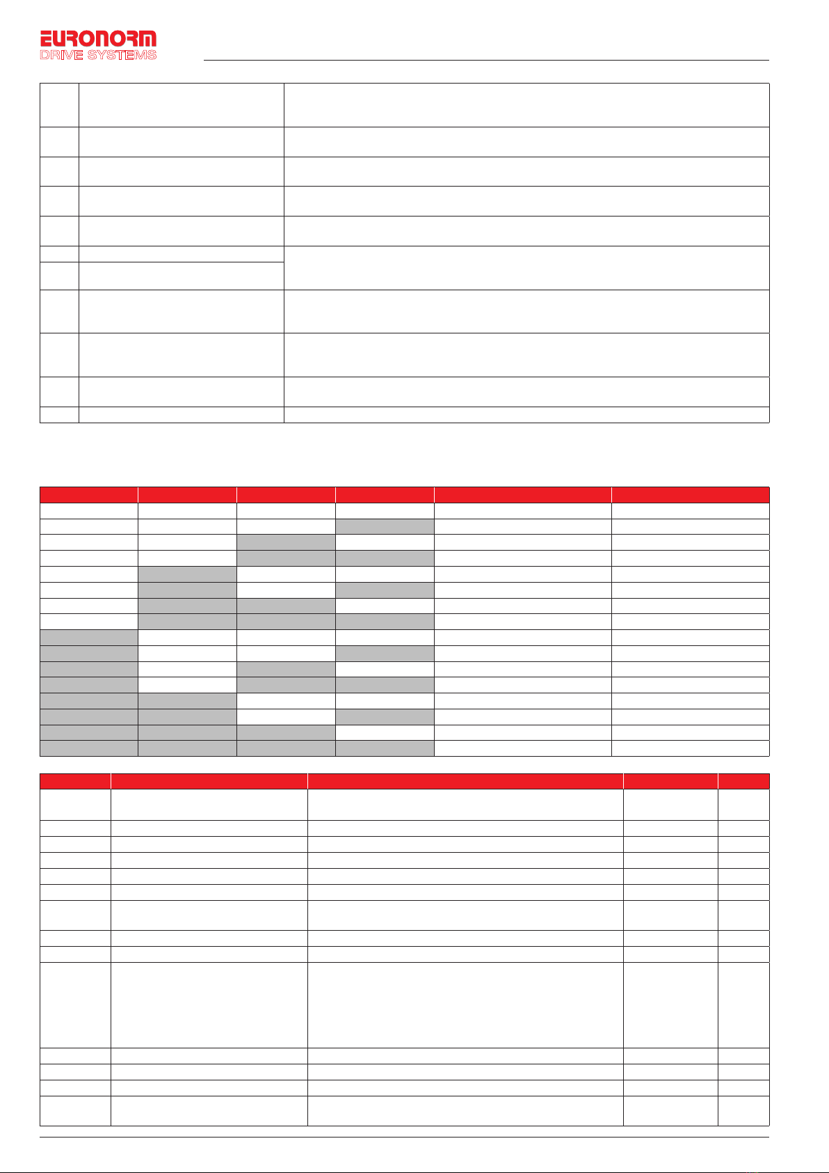
7. Parameter list
In JI150 series frequency inverters ,some parameters are “manufacturer reserved”, and their serial numbers are not listed
in the function parameter table,which leads to the discontinuity of some parameter serial numbers in the table. For the
parameters not introduced in the manual, please do not attempt to modify them to avoid causing errors.
d0 group Monitoring function group
Code Parameter name Functional Description Factory setting
d0.00 Running frequency Inverter theoretical operating frequency 0.01Hz
d0.01 Set frequency Actual set frequency 0.01Hz
d0.02 DC bus voltage Detected value for DC bus voltage 0.1V
d0.03 Output voltage Actual output voltage 1V
d0.04 Output current Effective value for Actual motor current 0.01A
d0.05 Output power Calculated value for motor output power 0.1kW
d0.06 Output torque Motor output torque percentage 0.1%
d0.07 DI input status DI input status -
d0.08 DO output status DO output status -
d0.09 AI1 voltage AI1 input voltage value 0.01V
d0.12 Count value Actual pulse count value in counting function -
d0.13 Length value Actual length in fixed length function - -
d0.14 Actual operating speed Motor actual running speed -
d0.15 PID setting Reference value percentage when PID runs %
d0.16 PID feedback Feedback value percentage when PID runs %
d0.17 PLC stage PLC Stage display when PLC runs -
d0.19 Feedback speed Inverter actual output frequency 0.01Hz
d0.20 Remaining run time Remaining run time display, it is for timing run control 0.1Min
d0.22 Current power-on time Total time of current inverter power-on 1Min
d0.23 Current run time Total time of current inverter run 0.1Min
d0.25 Communication set value Frequency, torque or other command values set by communication port 0.01%
d0.27 Master frequency setting display Frequency set by F0.03 master frequency setting source 0.01Hz
d0.28 Auxiliary frequency setting display Frequency set by F0.04 auxiliary frequency setting source 0.01Hz
d0.35 Inverter status Display the running and standby etc status information -
d0.36 Inverter type 1:G type: Suitable for constant torque load -
d0.37 AI1 voltage before correction Input voltage value before linear correction of AI1 0.01V

Hub van Doorneweg 8 • 2171 KZ Sassenheim – NL • T+31(0)252 228850 • F+31(0)252 228235 • E[email protected] • Ieuronormdrives.com
10 11
EURN010000_002_C
EURN010000_002_C
F0 group Basic Functional Parameter Group
Code Parameter name Setting range Factory setting Change
F0.00 Motor control mode 0: Vector control without PG ; 2:V/F control 2 ★
F0.01 Keyboard set frequency 0.00Hz~F0.19(Maximum frequency) 50.00Hz ☆
F0.02 Frequency command resolution 1: 0.1Hz
2: 0.01Hz 2★
F0.03 Frequency source master setting
0: Keyboard set frequency (F0.01 ,UP/DOWN can be modified,
power-down without memory)
1: Keyboard set frequency (F0.01 ,UP/DOWNcan be modified,
power-down with memory);
2: Analog AI1 setting;
4: Panel potentiometer setting (External keyboard use);
6: Multi-speed operation setting ;
7: Simple PLC program setting;
8: PID control setting;
9: Remote communications setting
1★
F0.04 Frequency source auxiliary setting Same as F0.03 setting 0 ★
F0.05 Reference object selection for
frequency source auxiliary setting
0. Relative to maximum frequency;
1. Relative to master frequency source 1
2. Relative to master frequency source 2
0☆
F0.06 Frequency source auxiliary setting
range 0%~150% 100% ☆
F0.07 Frequency superimposed selection
Units digit: Frequency source selection;
Tens digit: Arithmetic relationship of master and auxiliary for
frequency soruce
00 ☆
F0.08 Auxiliary offset frequency 0.00Hz~F0.19 (Maximum frequency) 0.00Hz ☆
F0.09 Shutdown memory selection 0: W/O memory;
1: With memory 1☆
F0.10 Frequency command UP/DOWN
reference when running
0: Running frequency;
1: Set frequency 0★
F0.11 Command source selection
Keyboard control (LED off);
1. Terminal block control (LED on)
2. Communications command control (LED flashes)
3. Keyboard control+ Communications command control
4. Keyboard control+ Communications command control +
Terminal block control
0☆
F0.12 Binding frequency source for
command source
Units digit: Keyboard command binding frequency source selection
0: Not binded;
1: Keyboard set frequency;
2: AI1 setting;
4: Panel potentiometer setting (External keyboard)
6: Multi-speed setting;
7: Simple PLC setting;
8: PID setting;
9: Communications reference
Tens digit: Terminal command binding frequency source selection
(0~9, same as units digit)
Hundreds digit: Communication command binding frequency source
selection (0~9, same as units digit)
000 ☆
F0.13 Acceleration time1 0.0s~6500s Depends on
models ☆
F0.14 Deceleration time1 0.0s~6500s Depends on
models ☆
F0.15 Ac/Deceleration time unit 0: 1s; 1: 0.1s; 2: 0.01s 1 ★
F0.16 Ac/deceleration time reference
frequency
0: F0.19 (Maximum frequency) 1: Set frequency;
2: 100Hz 0★
F0.17 Carrier frequency adjustment 0: NO ;
1: YES 0☆
F0.18 Carrier Frequency 0.5kHz~16.0kHz Depends on
models ☆
F0.19 Maximum output frequency 50.00Hz~320.00Hz 50.00Hz ★
F0.20 Upper limit frequency source 0: F0.21 setting; 1: Analog AI1 setting;
5: Communications reference 0★
F0.21 Upper limit frequency F0.23 (Lower limit frequency) ~ F0.19 (Maximum frequency) 50.00Hz ☆
F0.22 Upper limit frequency offset 0.00Hz~F0.19 (Maximum frequency) 0.00Hz ☆
F0.23 Lower limit frequency 0.00Hz~F0.21 (Upper limit frequency ) 0.00Hz ☆
F0.24 Running direction 0: Same direction; 1: Opposite direction 0 ☆
F0.26 AIAnalog accuracy 0: 0.01Hz; 1: 0.05Hz;
2: 0.1Hz; 3: 0.5Hz 1☆

Hub van Doorneweg 8 • 2171 KZ Sassenheim – NL • T+31(0)252 228850 • F+31(0)252 228235 • Esales@euronorm.nl • Ieuronormdrives.com
Hub van Doorneweg 8 • 2171 KZ Sassenheim – NL • T+31(0)252 228850 • F+31(0)252 228235 • E[email protected] • Ieuronormdrives.com
10 11
EURN010000_002_C
EURN010000_002_C
F1 group Input terminals
Code Parameter name Setting range Factory setting Change
F1.00 DI1 terminal function selection
0~51
1★
F1.01 DI2 terminal function selection 2 ★
F1.02 DI3 terminal function selection 8 ★
F1.03 DI4 terminal function selection 9 ★
F1.04 DI5 terminal function selection 0 ★
The functions of digital multi-functional input terminal DI1~DI5 can be set by parameter F1.00~F1.04.
The optional functions are shown in the following table
Set
value
Function Description
0 No function The terminal for not use can be set to “no function” to prevent accidental operation.
1 Forward run (FWD) External terminals are used to control the FWD run mode of inverter.
2 Reverse run (REV) External terminals are used to control the REV run mode of inverter.
3 Three-wire operation control This terminal is used to determine the inverter’s three-wire control mode. For details, please refer to
the instructions of function code F1.10 (“terminal command mode).
4 Forward JOG(FJOG)
FJOG means Forward JOG running, RJOG means Reverse JOG running. For Jog running
frequency and Jog Ac/deceleration time, please refer to the description of the function code F7.00,
F7.01, F7.02.
5 Reverse JOG(RJOG) Modify frequency increment/decrement command when the frequency is referenced by external
terminal. Adjust up/down the set frequency when the digital setting is selected as the frequency
source.
6 Terminal UP
7 Terminal DOWN
8 Free stop The inverter output is blocked, at the time, the parking process of motor is not controlled by the
inverter. This way is same as the principle of free stop described in F3.07.
9 Fault reset (RESET) The function make use of terminal for fault reset. It has same function with RESET key on the
keyboard. This function can be used to realize remote fault reset
10 Run pausing
The inverter slows down and stops,but all operating parameters are memorized.Such as PLC
parameters,wobbulate frequency parameters, and PID parameters. This terminal signal disappears,
the inverter reverts to the previous state of running before parking
11 External fault normally open input When the signal is sent to the inverter, the inverter reports fault Err.15, and performs troubleshooting
according to fault protection action (For details, please refer to the function code F8.17)
12 Multi-speed terminal 1
The setting of 16 stage speed or 16 kinds of other command can be achieved through the 16
states of the four terminals.
13 Multi-speed terminal 2
14 Multi-speed terminal 3
15 Multi-speed terminal 4
16 Ac/deceleration time selection terminal 1 The selection of 4 ac/deceleration times can be achieved through the 4 states of the two terminals.
17 Ac/deceleration time selection terminal 2
18 Frequency source switching
Used to switch between different frequency sources.
According to the setting of frequency source selection function code (F0.07) , the terminal is used to
switch between two frequency sources
19 UP/DOWN setting (Terminal, keyboard)
When the frequency reference is the digital frequency, this terminal is used to clear the changed
frequency value by terminal UP/DOWN or keyboard UP/DOWN, so that the reference frequency can
recover to the set value of F0.01
20 Run command switch terminal 1
When the command source is set to the terminal control (F0.11 =1), the terminal can be used to
switch between terminal control and keyboard control.
When the command source is set to the communication control(F0.11 = 2), the terminal can be
used to switch between communication control and keyboard control.
21 Ac/deceleration prohibited Ensure the inverter is free from external signals affect (Except for shutdown command), maintain
current output frequency.
22 PID pause PID is temporarily disabled, the inverter maintains current output frequency, no longer performs PID
adjustment of frequency source.
23 PLC status reset When PLC pauses and runs again, this terminal is used to reset the inverter to the initial state of
simple PLC.
24 Wobbulate pause When the inverter outputs at center frequency. Wobbulate will pause
25 Counter input Input terminal of the count pulse
26 Counter reset Clear counter status
27 Length count input Input terminal of the length count.
28 Length reset Clear length
32 Immediately DC braking If the terminal is active, the inverter switches directly to DC braking status
33 External fault normally closed input When the signal of external fault normally closed input is inputted into the inverter, the inverter will
report fault Err.15 and shutdown.
34 Frequency change enable If the function is set to be valid, when the frequency changes, the inverter does not respond to
frequency changes until the terminal state is invalid.
35 PID action direction as reverse If the terminal is valid, PID action direction opposites to the direction set by E2.03
36 External parking terminal 1 Under keyboard control mode, the terminal can be used to stop the inverter, same as STOP key on
the keyboard.
Hub van Doorneweg 8 • 2171 KZ Sassenheim – NL • T+31(0)252 228850 • F+31(0)252 228235 • E[email protected] • Ieuronormdrives.com
12 13
EURN010000_002_C
EURN010000_002_C
37 Control command switch terminal 2
Used to switch between terminal control and communication control. If the command source is
selected as terminal control, the system will be switched to the communication control mode when
the terminal is active; vice versa.
38 PID integral pause When the terminal is active, the PID integral adjustment function is paused, but the proportion and
differential adjustments of PID are still valid.
39 Switch between frequency source
master setting and preset frequency When the terminal is active, the frequency source A is replaced by the preset frequency (F0.01)
40 Switch between frequency source
auxiliary setting and preset frequency When the terminal is active, the frequency source B is replaced with the preset frequency (F0.01)
43 PID parameter switching When DI terminal (E2.19 = 1) is used to switch PID parameters, if the terminal is invalid, PID
parameters use E2.13~E2.15; if the terminal is valid, PID parameters use E2.16~E2.18
44 Custom fault 1 When custom fault 1 and custom fault 2 are active, the inverter respectively alarms fault Err.27 and
fault Err.28, and deals with them according to the mode selected by the fault protection action
F8.19.
45 Custom fault 2
47 Emergency parking
If the terminal is valid, the inverter will park at the fastest speed, and the current maintains at the
set upper limit during the parking process. This function is used to meet the requirements that the
inverter needs to stop as soon as possible when the system is in a emergency state.
48 External parking terminal 2
In any control mode (Keyboard control, terminal control, communication control), the terminal
can be used to decelerate the inverter until stop, at the time the deceleration time is fixed for
deceleration time 4.
49 Deceleration DC braking If the terminal is valid, firstly the inverter decelerates to the initial frequency of stop DC braking, and
then switches directly to DC braking status.
50 Clear current running time If the terminal is valid, the inverter’s current running time is cleared
Table 1 Multi command functions description:Over 4 segments command terminal, can be combined into 16 states,
each state corresponds to the 16 instruction set value. As shown in Table 1 below:
K4 K3 K2 K1 Command Setting Parameters
OFF OFF OFF OFF 0-Stage speed setting 0X E1.00
OFF OFF OFF ON 1-Stage speed setting 1X E1.01
OFF OFF ON OFF 2-Stage speed setting 2X E1.02
OFF OFF ON ON 3-Stage speed setting 3X E1.03
OFF ON OFF OFF 4-Stage speed setting 4X E1.04
OFF ON OFF ON 5-Stage speed setting 5X E1.05
OFF ON ON OFF 6-Stage speed setting 6X E1.06
OFF ON ON ON 7-Stage speed setting 7X E1.07
ON OFF OFF OFF 8-Stage speed setting 8X E1.08
ON OFF OFF ON 9-Stage speed setting 9X E1.09
ON OFF ON OFF 10-Stage speed setting 10X E1.10
ON OFF ON ON 11-Stage speed setting 11X E1.11
ON ON OFF OFF 12-Stage speed setting 12X E1.12
ON ON OFF ON 13-Stage speed setting 13X E1.13
ON ON ON OFF 14-Stage speed setting 14X E1.14
ON ON ON ON 15 Stage speed setting 15X E1.15
Code Parameter name Setting range Factory setting Change
F1.10 Terminal command mode 0: Two-wire type 1 1; 1: Two-wire type 2 2;
2: Three-wire type 1; 3: Three-wire type 2 0★
F1.11 TerminalUP/DOWN 0.001Hz/s~65.535Hz/s 1.000Hz/s ☆
F1.12 Minimum input for AIC1 0.00V~F1.14 0.30V ☆
F1.13 F1.12 corresponding setting -100.0%~+100.0% 0.0% ☆
F1.14 Maximum input for AIC1 F1.12~+10.00V 10.00V ☆
F1.15 F1.14 corresponding setting -100.0%~+100.0% 100.0% ☆
F1.25 AIinput setting selection Units digit:AI1 AI1 Below the minimum input setting selection
0: Corresponding to the minimum input set 1:0.0%; 000 ☆
F1.30 DI filter time 0.000s~1.000s 0.010s ☆
F1.31 AI1 filter time 0.00s~10.00s 0.10s ☆
F1.35 DI terminal Mode slection 1
Units digit:DI1 :
0: High level active; 1: Low level active
Tens digit: DI2 (Same as the units digit);
Hundreds digit: DI3 (Same as the units digit)
Thousands digit: DI4 (Same as the units digit));
Ten thousands digit: DI5 (Same as the units digit)
00000 ★
F1.37 DI1 delay time 0.0s~3600.0s 0.0s ★
F1.38 DI2 delay time 0.0s~3600.0s 0.0s ★
F1.39 DI3 delay time 0.0s~3600.0s 0.0s ★
F1.40 Define the input terminal repeat 0: Unrepeatable;
1: Repeatable 0★

Hub van Doorneweg 8 • 2171 KZ Sassenheim – NL • T+31(0)252 228850 • F+31(0)252 228235 • Esales@euronorm.nl • Ieuronormdrives.com
Hub van Doorneweg 8 • 2171 KZ Sassenheim – NL • T+31(0)252 228850 • F+31(0)252 228235 • E[email protected] • Ieuronormdrives.com
12 13
EURN010000_002_C
EURN010000_002_C
F2 group Output terminal
Code Parameter name Setting range Factory setting Change
F2.02 Relay output function selection (TA.TC) 0~40 2 ☆
Relay output function description:
Setting
value
Functions Description
0 No output No output action
1 Inverter running Inverter is in running state, the output frequency (Can be zero),the output ON signal.
2 Fault output (Fault down ) When the drive fails and downtime, the output ON signal.
3 Frequency level detection FDT1 output Please refer to the function code F7.23, F7.24’s instructions.
4 Frequency arrival Please refer to the description of function code F7.25.
5Zero-speed running (No output when
shutdown)
Inverter operation and the output frequency is 0, output ON signal. When the drive is shut
down, the signal is OFF.
6 Motor overload pre-alarm
Before the motor overload protection, according to the overload pre-alarm threshold value
judgment, more than the pre-alarm threshold value output ON signal. Motor overload
parameter settings refer to the function code F8.02~F8.04.
7 Inverter overload pre- alarm Before the inverter overload occurs 10s, output ON signal. Setup counter arrive.
8 Setup counter arrive When the count reaches the set value of E0.08, output ON signal. Specifies the count value
reaches.
9 Specifies the count value reaches When the count reaches the set value of E0.09, output ON signal. Counting Function
Reference E0 group.
10 Length arrival When the actual length of the detection of more than E0.05 set length, output ON signal.
11 PLC cycle is complete After simple PLC completes one cycle, the output of a pulse width of 250ms signal.
12 Total running time arrival Inverter total running time of more than F7.21 F6.07 set time,the output ON signal.
13 Limited in frequency When the set frequency exceeds the upper limit frequency or lower frequency, and output
frequency is beyond the upper limit frequency or lower limit frequency, output ON signal.
14 Torque limiting Drive under the speed control mode, when the output torque reaches the torque limit, the
inverter is stall protection status, while the output ON signal.
15 Ready to run When the inverter main circuit and control circuit power supply has stabilized, and the drive
does not detect any fault information, the drive is in an operational state, output ON signal.
17 Upper frequency arrival When the operating frequency reaches the upper frequency,output ON signal.
18 The lower frequency arrival
(No output when shutdown)
When the operating frequency reaches the lower frequency, output ON signal. The next stop
status signal is OFF.
19 Under voltage state output When the inverter is in an undervoltage condition, output ON signal.
20 Communication setting Refer to the communication protocol.
23 Zero-speed operation 2
(Shutdown also output) The inverter‟s output frequency is 0, output ON signal. The signal is also ON when shutdown.
24 Cumulative power-on time arrival When the inverter’s accumulated power on time (F6.08) over F7.20 the set time, the output ON
signal.
25 Frequency level detection FDT2 output Please refer to the function code F7.26, F7.27’s instructions.
26 Frequency 1 reaches output Please refer to the function code F7.28, F7.29’s instructions.
27 Frequency 2 reaches output Please refer to the function code F7.30, F7.31’s instructions.
28 Current 1 reaches output Please refer to the function code F7.36, F7.37’s instructions.
29 Current 2 reaches output Please refer to the function code F7.38, F7.39’s instructions.
30 Timing reach output When the timer function selection (F7.42) is valid, the drive time to reach this run after the set
time runs out, output ON signal.
31 AI1 input overrun When the value of analog input AI1 greater than F7.51 (AI1 input protection limit) or less than
F7.50 (AI1 input protection under), output ON signal.
33 Off load When the inverter is off-load state, output ON signal.
34 Reverse operation Inverter in reverse run, output ON signal
35 0 current state Refer to the description of function code F7.32, F7.33.
36 Module temperature reaches Inverter module heatsink temperature (F6.06) reach the set module temperature reaches value
(F7.40), output signal ON.
37 Software current limit Please refer to the function code F7.34, F7.35’s instructions.
38 The lower frequency arrival
(Stop and output)
When the operating frequency reaches the lower limit frequency, output ON signal. In
shutdown state of the signal is also ON.
40 Current running time of arrival When the inverter starts running time is longer than the time set by F7.45, it outputs ON signal.
Hub van Doorneweg 8 • 2171 KZ Sassenheim – NL • T+31(0)252 228850 • F+31(0)252 228235 • E[email protected] • Ieuronormdrives.com
14 15
EURN010000_002_C
EURN010000_002_C
Code Parameter name Setting range Factory setting Change
F2.07 DA1 output function selection 0~17 2 ☆
Analog Output DA output range is 0V~10V, or 0mA~20mA, with the corresponding scaling
function relationship in the following table
Setting
value
Functions Description
0 Running frequency 0~max. output frequency
1 Set frequency 0~max. output frequency
2 Output current 0~2 times the motor rated current
3 Output torque 0~2 times the motor rated toqure
4 Output power 0~2 times rated power
5 Output voltage 0~1.2 times inverter rated voltage
7 Anolog AI1 0V~10V(Or 0~20mA)
10 Lentgh value 0~max. setting length
11 The count value 0~max. count value
12 Coummunication set 0.0%~100.0%
13 Motor speed 0~max. output frequency correspondent speed
14 Output current 0.0A~100.0A(Inverter power≦55kW);
0.0A~1000.0A(Inverter power>55kW)
15 DC bus voltage 0.0V~1000.0V
17 Frequency source main set 0~max. output frequency
F2.11 Relay 1 output delay time 0.0s~3600.0s 0.0s ☆
F2.15 DO terminal active status selection Units digit: Reserve
Tens digit: Relay 0: Positive; 1: Negtive 00000 ☆
F2.16 DA1 zero bias coefficient -100.0%~+100.0% 20.0% ☆
F2.17 DA1 gain -10.00~+10.00 0.8 ☆
F3 group Start and stop control group
Code Parameter name Setting range Factory setting Change
F3.00 Start-up mode
0: Direct startup;
1: Speed tracking restart
2: Pre-excitation start (AC asynchronous motor)
0☆
F3.01 Speed tracking mode 3: Hard speed tracking mode 3 ★
F3.02 Speed tracking speed 0~100 20 ☆
F3.03 Start frequency 0.00Hz~10.00Hz 0.00Hz ☆
F3.04 Hold time for start frequency 0.0s~100.0s 0.0s ★
F3.05 DC pre-excitation current 0%~100% 0% ★
F3.06 DC pre-excitation time 0.0s~100.0s 0.0s ★
F3.07 Stop mode 0: Deceleration stop; 1: Free stop 0 ☆
F3.08 DC start frequency 0.00Hz~F0.19(Max.frequency) 0.00Hz ☆
F3.09 DC waiting time 0.0s~100.0s 0.0s ☆
F3.10 Braking current 0%~100% 0% ☆
F3.11 Braking time 0.0s~100.0s 0.0s ☆
F3.12 Braking utilization rate 0%~100% 100% ☆
F3.13 Ac/deceleration mode
0: Linear acceleration and deceleration;
1: S curve acceleration and deceleration A
2: S curve acceleration and deceleration B
0★
F3.14 Proportion of S curve start-section 0.0%~(100.0%.~F3.15) 30.0% ★
F3.15 Proportion of S curve end-section 0.0%~(100.0%.~F3.14) 30.0% ★

Hub van Doorneweg 8 • 2171 KZ Sassenheim – NL • T+31(0)252 228850 • F+31(0)252 228235 • Esales@euronorm.nl • Ieuronormdrives.com
Hub van Doorneweg 8 • 2171 KZ Sassenheim – NL • T+31(0)252 228850 • F+31(0)252 228235 • E[email protected] • Ieuronormdrives.com
14 15
EURN010000_002_C
EURN010000_002_C
F4 group V/F control parameter group
Code Parameter name Setting range Factory setting Change
F4.00 V/F curve setting
0: Linear V/F;
1: Multi-point V/F;
2: Square V/F;
3: 1.2th power V/F;
4: 1.4th power V/F;
6: 1.6th power V/F;
8: 1.8th power V/F;
10: V/F completely separate;
11: V/F half separate
0★
F4.01 Torque boost 0.0% (Automatic torque boost)
0.1~30% 0.0% ★
F4.02 Torque boost cut-off frequency 0.00Hz~F0.19 (Max. Frequency) 15.00Hz ★
F4.03 Multi-point V/F frequency point 1 0.00Hz~F4.05 0.00Hz ★
F4.04 Multi-point V/F voltage point V1 0.0%~100.0% 0.0% ★
F4.05 Multi-point V/F frequency point 2 F4.03~F4.07 0.00Hz ★
F4.06 Multi-point V/F voltage point V2 0.0%~100.0% 0.0% ★
F4.07 Multi-point V/F frequency point 3 F4.05~b0.04 (Motor rated frequency) 0.00Hz ★
F4.08 Multi-point V/F voltage point V3 0.0%~100.0% 0.0% ★
F4.09 V/F slip compensation gain 0.0%~200.0% 0.0% ☆
F4.10 V/F overexcitation gain 0~200 80 ☆
F4.11 V/F oscillation suppression gain 0~100 0 ☆
F4.12 V/F separation voltage source 0~9 0 ☆
F4.13 V/F separation voltage digital setting 0V~motor rated voltage 0V ☆
F4.14 V/F separation voltage rise time 0.0s~1000.0s 0.0s ☆
F5 group Vector control parameter group
Code Parameter name Setting range Factory setting Change
F5.00 Proportion of speed loop G1 1 ~ 100 30 ☆
F5.01 Speed loop integral T1 0.01s ~ 10.00s 0.50s ☆
F5.02 Switching frequency 1 0.00 ~ F5.05 5.00Hz ☆
F5.03 Proportion of speed loop G2 0 ~ 100 20 ☆
F5.04 Speed loop integral T2 0.01s ~ 10.00s 1.00s ☆
F5.05 Switching frequency 2 F5.02 ~ F0.19(Max. frequency) 10.00Hz ☆
F5.06 Speed loop integral 0: Invalid; 1: Valid 0 ☆
F5.07 Torque limit source under speed control
mode
0: Function code F5.08 set; 1: AI1 set;
5: Communication set 0☆
F5.08 Torque upper limit digital setting 0.0% ~ 200.0% 150.0% ☆
F5.09 Vector control differential gain 50% ~ 200% 150% ☆
F5.10 Speed loop filtering time 0.000s ~ 0.100s 0.000s ☆
F5.11 Vector control overexcitation gain 0 ~ 200 64 ☆
F5.12 Excitation regulator proportional gain 0 ~ 60000 2000 ☆
F5.13 Excitation regulator integral gain 0 ~ 60000 1300 ☆
F5.14 Torque regulator proportional gain 0 ~ 60000 2000 ☆
F5.15 Torque regulator integral gain 0 ~ 60000 1300 ☆

Hub van Doorneweg 8 • 2171 KZ Sassenheim – NL • T+31(0)252 228850 • F+31(0)252 228235 • E[email protected] • Ieuronormdrives.com
16 17
EURN010000_002_C
EURN010000_002_C
F6 group Keyboard and display
Code Parameter name Setting range Factory setting Change
F6.00 STOP/RESET key functions
0: STOP/RESET key is enabled only under keyboard operation
mode
1: STOP/RESET key is enabled under any operation mode
1☆
F6.01 Running status display parameters 1 0x0000 ~ 0xFFFF 001F ☆
F6.02 Running status display parameters 2 0x0000 ~ 0xFFFF 0000 ☆
F6.03 Stop status display parameters 0x0001 ~ 0xFFFF 0033 ☆
F6.04 Load speed display coefficient 0.0001 ~ 6.5000 3.0000 ☆
F6.05 Decimal places for load speed display 0:0 decimal place; 2:2 decimal place
1:1 decimal place; 3:3 decimal place 1☆
F6.06 Inverter module radiator temperature 0.0℃~ 100.0℃-●
F6.07 Total running time 0h ~ 65535h - ●
F6.08 Total power-on time 0h ~ 65535h - ●
F6.09 Total power consumption 0 ~ 65535℃-●
F6.10 Product number Inverter product number - ●
F6.11 Software version Software version of control board - ●
F6.13 Communication read and write data
selection
Single digit: CRC mistake selection:
0: Reply verification error;
1: No reply on verification error;
Ten digit: Broadcast message screening selection:
0-no screening; 1-screening
Hundred digit: Inverter fault information Read selection:
0-read; 1-no read
011 ☆
F6.17 Power correction coefficient 0.00 ~ 10.00 1.00 ☆
F6.20 Keyboard lock selection
0: Only RUN and STOP keyps are valid;
2: Only RUN, STOP, UP, DOWN keys are valid;
3: Only STOP key is valid
0☆
F6.21 QUICK key Function Selection
0: No function;
1: Jog running;
2: Shit key;
3: Forward/reverse running switching;
4: Clear UP/DOWN setting;
5: Free stop;
6: Running command given in sequence
1☆

Hub van Doorneweg 8 • 2171 KZ Sassenheim – NL • T+31(0)252 228850 • F+31(0)252 228235 • Esales@euronorm.nl • Ieuronormdrives.com
Hub van Doorneweg 8 • 2171 KZ Sassenheim – NL • T+31(0)252 228850 • F+31(0)252 228235 • E[email protected] • Ieuronormdrives.com
16 17
EURN010000_002_C
EURN010000_002_C
F7 group Auxiliary function parameter group
Code Parameter name Setting range Factory setting Change
F7.00 Jog running frequency 0.00Hz ~ F0.19 (Max. frequency) 6.00Hz ☆
F7.01 Jog acceleration time 0.0s ~ 6500.0s 5.0s ☆
F7.02 Jog deceleration time 0.0s ~ 6500.0s 5.0s ☆
F7.03 Jog priority 0: Invalid; 1: Valid 1 ☆
F7.04 Jump frequency 1 0.00Hz ~ F0.19 (Max. frequency) 0.00Hz ☆
F7.05 Jump frequency 2 0.00Hz ~ F0.19 (Max. frequency) 0.00Hz ☆
F7.06 Jump frequency range 0.00Hz ~ F0.19 (Max. frequency) 0.00Hz ☆
F7.07 Jump frequency availability 0: Invalid; 1: Valid 0 ☆
F7.08 Acceleration time 2 0.0s ~ 6500.0s Depends on models ☆
F7.09 Deceleration time 2 0.0s ~ 6500.0s Depends on models ☆
F7.10 Acceleration time 3 0.0s ~ 6500.0s Depends on models ☆
F7.11 Deceleration time 3 0.0s ~ 6500.0s Depends on models ☆
F7.12 Acceleration time 4 0.0s ~ 6500.0s Depends on models ☆
F7.13 Deceleration time 4 0.0s ~ 6500.0s Depends on models ☆
F7.14 Switching frequency point between
acceleration time 1 and acceleration time 2 0.00Hz ~ F0.19 (Max. frequency) 0.00Hz ☆
F7.15 Switching frequency point between
deceleration time 1 and deceleration time 2 0.00Hz ~ F0.19 (Max. frequency) 0.00Hz ☆
F7.16 Forward/reverse rotation dead-band 0.00s ~ 3600.0s 0.00s ☆
F7.17 Reverse rotation control 0: Allow; 1: Prohibit 0 ☆
F7.18 Mode under lower limit frequency 0: Running at lower limit frequency;
1: Stop; 2: Running at zero speed 0☆
F7.19 Droop control 0.00Hz ~ 10.00Hz 0.00Hz ☆
F7.20 Setting of power-on arrival time 0h ~ 36000h 0h ☆
F7.21 Setting of running arrival time 0h ~ 36000h 0h ☆
F7.22 Start protection selection 0: OFF; 1: ON 0 ☆
F7.23 FDT1 detection value 0.00Hz ~ F0.19 (Max. frequency) 50.00Hz ☆
F7.24 FDT1 detection hysteresis value 0.0% ~ 100.0% (FDT1 level) 5.0% ☆
F7.25 Frequency reaches detection width 0.00 ~ 100% (Max. frequency) 0.0% ☆
F7.26 FDT2 detection value 0.00Hz ~ F0.19 (Max. frequency) 50.00Hz ☆
F7.27 FDT2 detection hysteresis value 0.0% ~ 100.0% (FDT2 level) 5.0% ☆
F7.28 Frequency detection value 1 0.00Hz ~ F0.19 (Max. frequency) 50.00Hz ☆
F7.29 Frequency detection width 1 0.0% ~ 100.0% (Max. frequency) 0.0% ☆
F7.30 Frequency detection value 2 0.00Hz ~ F0.19 (Max. frequency) 50.00Hz ☆
F7.31 Frequency detection width 2 0.0% ~ 100.0% (Max. frequency) 0.0% ☆
F7.32 0 current detection 0.0% ~ 300.0% (Motor rated current) 5.0% ☆
F7.33 0 current delay 0.01s ~ 360.00s 0.10s ☆
F7.34 Current over-run value 0.0% (Not detected);
0.1% ~ 300.0% (Max. frequency) 200.0% ☆
F7.35 Current over-run time 0.00s ~ 360.00s 0.00s ☆
F7.36 Arrival current 1 0.0% ~ 300.0% (Motor rated current) 100.0% ☆
F7.37 Current 1 width 0.0% ~ 300.0% (Motor rated current) 0.0% ☆
F7.38 Arrival current 1 0.0% ~ 300.0% (Motor rated current) 100.0% ☆
F7.39 Current 1 width 0.0% ~ 300.0% (Motor rated current) 0.0% ☆
F7.40 Module temperature arrival 0℃~ 100℃75℃☆
F7.41 Cooling fan control 0: Fan run when inverter is running;
1: Fan keep running 0☆
F7.42 Timing function selection 0: Invalid; 1: Valid 0 ★
F7.43 Timing run time selection 0: F7.44 set; 1: AI1 set;
Note: Analog input range correspond to F7.44 0★
F7.44 Timing run time 0.0Min ~ 6500.0Min 0.0Min ★
F7.45 Running time arrive 0.0Min ~ 6500.0Min 0.0Min ★
F7.46 Awaken frequency Dormancy frequency (F7.48)~maximum frequency (F0.19) 0.00Hz ☆
F7.47 Awaken delay time 0.0s ~ 6500.0s 0.0s ☆
F7.48 Dormancy frequency 0.00Hz ~ awaken frequency (F7.46) 0.00Hz ☆
F7.49 Dormancy delay time 0.0s ~ 6500.0s 0.0s ☆
F7.50 AI1 input voltage protection lower limit 0.00V ~ F7.51 3.1V ☆
F7.51 AI1 input voltage protection upper limit F7.50 ~ 10.00V 6.8V ☆

Hub van Doorneweg 8 • 2171 KZ Sassenheim – NL • T+31(0)252 228850 • F+31(0)252 228235 • E[email protected] • Ieuronormdrives.com
18 19
EURN010000_002_C
EURN010000_002_C
F8 group Fault and protection parameter group
Code Parameter name Setting range Factory setting Change
F8.00 Overcurrent stall gain 0~100 20 ☆
F8.01 Lost speed stall protection current 100%~200% - ☆
F8.02 Overload protection 0:Prohibit; 1:Allow 1 ☆
F8.03 Motor overload protection gain 0.20~10.00 1.00 ☆
F8.04 Motor overload pre-alarm coefficient 50%~100% 80% ☆
F8.05 Overvoltage stall gain 0(No overvoltage stall)~100 0 ☆
F8.06 Overvoltage stall protection voltage /
energy consumption brake voltage 120%~150%(Three-phase) 130% ☆
F8.08 Output phase loss protection 0:Prohibit; 1:Allow 1 ☆
F8.09 Short to ground protection 0:Invalid; 1:Valid 1 ☆
F8.10 Number of automatic fault reset 0 ~ 32767 0 ☆
F8.11 Fault DO action selection during
automatic fault 0:OFF ; 1:ON 0 ☆
F8.12 Automatic fault reset 0.1s ~ 100.0s 1.0s ☆
F8.25 Abnormal reserve frequency 60.0% ~ 100.0% 100% ☆
F8.26 Momentary power cut action selection 0: Invalid; 1: Deceleration;
2: Deceleration and stop 0☆
F8.28 Recovery voltage judgment time of
momentary power cut 0.00s ~ 100.00s 0.50s ☆
F8.29 Judgment voltage of momentary power
cut 50.0% ~ 100.0%(Standard bus voltage) 80% ☆
F9 group Communication parameter group
Code Parameter name Setting range Factory setting Change
F9.00 Baud rate
Unit:Modbus
2: 1200BPS;
3: 2400BPS;
4: 4800BPS;
5: 9600BPS;
6: 19200BPS;
7: 38400BPS;
8: 57600BPS;
9: 115200BPS
Tens digit: Reserved;
Hundreds digit : Reserved
Thousands digit:Reserved
6005 ☆
F9.01 Data format
0: No parity (8-N-2);
1: Even parity (8-E-1)
2: Odd parity (8-O-1)
3: No parity (8-N-1)
0☆
F9.02 This unit address 1 ~ 250 ,for broadcast address 1 ☆
F9.03 Response delay 0ms ~ 20ms 2ms ☆
F9.04 Communication timeout time 0.0 (Invalid ); 0.1 ~ 60.0s 0.0 ☆
F9.05 Data transfer format selection
Units digit:Modbus
0: Non-standard Modbus protocol;
1: Stand Modbus protocol
Tens digit: Reserved
31 ☆
F9.06 Communication read current resolution 0:0.01A ; 1:0.1A 0 ☆

Hub van Doorneweg 8 • 2171 KZ Sassenheim – NL • T+31(0)252 228850 • F+31(0)252 228235 • Esales@euronorm.nl • Ieuronormdrives.com
Hub van Doorneweg 8 • 2171 KZ Sassenheim – NL • T+31(0)252 228850 • F+31(0)252 228235 • E[email protected] • Ieuronormdrives.com
18 19
EURN010000_002_C
EURN010000_002_C
Fb group Control parameter optimization group
Code Parameter name Setting range Factory setting Change
Fb.00 Fast current limiting manner 0: Disable; 1: Enable 1 ☆
Fb.01 Undervoltage point setting 50.0% ~ 140.0% 100.0% ☆
Fb.02 Overvoltage point setting 200.0 ~ 2500.0V - ★
Fb.03 Deadband compensation mode
selection
0: No compensation;
1: Compensation mode 1;
2: Compensation mode 2
1☆
Fb.04 Current detection compensation 0 ~ 100 5 ☆
Fb.05 Vector optimization without PG mode
selection
0: No compensation;
1: Compensation mode 1;
2: Compensation mode 2
1★
Fb.06 Upper limiting frequency for DPWM
switching 0.00 ~ 15.00Hz 12.00Hz ☆
Fb.07 PWM modulation mode 0: Asynchronous; 1: Synchronous 0 ☆
Fb.08 Random PWM depth 0: Invalid
1 ~10:PWM carrier frequency random depth 0☆
E0 group Wobbulate, fixed-length and counting group
Code Parameter name Setting range Factory setting Change
E0.00 Swing setting manner 0: Relative to center frequency;
1: Relative to maximum Frequency 0☆
E0.01 Wobbulate range 0.0% ~ 100.0% 0.0% ☆
E0.02 Sudden jump frequency range 0.0% ~ 50.0% 0.0% ☆
E0.03 Wobbulate cycle 0.1s ~ 3000.0s 10.0s ☆
E0.04 Triangle wave rise time coefficient 0.1% ~ 100.0% 50.0% ☆
E0.05 Set length 0m ~ 65535m 1000m ☆
E0.06 Actual length 0m ~ 65535m 0m ☆
E0.07 Pulse per meter 0.1 ~ 6553.5 100.0 ☆
E0.08 Set count value 1 ~ 65535 1000 ☆
E0.09 Specified count value 1 ~ 65535 1000 ☆

Hub van Doorneweg 8 • 2171 KZ Sassenheim – NL • T+31(0)252 228850 • F+31(0)252 228235 • E[email protected] • Ieuronormdrives.com
20 21
EURN010000_002_C
EURN010000_002_C
E1 group Multi-speed, sample PLC parameter
Code Parameter name Setting range Factory setting Change
E1.00 0 stage speed setting 0X -100.0%~100.0% 0.0% ☆
E1.01 1 stage speed setting 1X -100.0%~100.0% 0.0% ☆
E1.02 2 stage speed setting 2X -100.0%~100.0% 0.0% ☆
E1.03 3 stage speed setting 3X -100.0%~100.0% 0.0% ☆
E1.04 4 stage speed setting 4X -100.0%~100.0% 0.0% ☆
E1.05 5 stage speed setting 5X -100.0%~100.0% 0.0% ☆
E1.06 6 stage speed setting 6X -100.0%~100.0% 0.0% ☆
E1.07 7 stage speed setting 7X -100.0%~100.0% 0.0% ☆
E1.08 8 stage speed setting 8X -100.0%~100.0% 0.0% ☆
E1.09 9 stage speed setting 9X -100.0%~100.0% 0.0% ☆
E1.10 10 stage speed setting 10X -100.0%~100.0% 0.0% ☆
E1.11 11 stage speed setting 11X -100.0%~100.0% 0.0% ☆
E1.12 12 stage speed setting 12X -100.0%~100.0% 0.0% ☆
E1.13 13 stage speed setting 13X -100.0%~100.0% 0.0% ☆
E1.14 14 stage speed setting 14X -100.0%~100.0% 0.0% ☆
E1.15 15 stage speed setting 15X -100.0%~100.0% 0.0% ☆
E1.16 PLC Simple PLC running mode
0: Stop after single running;
1: Hold final value after single
2: Circulating
0☆
E1.17 PLCmemory selection
Units:power-down memory;
0: Power-down without memory;
1: Power-down memory;
Tens:stop with memory;;
0: Stop without memory; 1:Stop memory
11 ☆
E1.18 0 stage running time ~ 0.0s(h) ~ 6500.0s(h) 0.0s(h) ☆
E1.19 0 stage ac/deceleration time selection 0: F0.13, F0.14; 1: F7.08, F7.09;
2: F7.10, F7.11; 3: F7.12, F7.13 0☆
E1.20 1 stage running time T1 0.0s(h) ~ 6500.0s(h) 0.0s(h) ☆
E1.21 1 stage ac/deceleration time selection Same to E1.19 0 ☆
E1.22 2 stage running time T2 0.0s(h) ~ 6500.0s(h) 0.0s(h) ☆
E1.23 2 stage ac/deceleration time selection Same to E1.19 0 ☆
E1.24 3 stage running time T3 0.0s(h) ~ 6500.0s(h) 0.0s(h) ☆
E1.25 3 stage ac/deceleration time selection Same to E1.19 0 ☆
E1.26 4 stage running time T4 0.0s(h) ~ 6500.0s(h) 0.0s(h) ☆
E1.27 4 stage ac/deceleration time selection Same to E1.19 0 ☆
E1.28 5 stage running time T5 0.0s(h) ~ 6500.0s(h) 0.0s(h) ☆
E1.29 5 stage ac/deceleration time selection Same to E1.19 0 ☆
E1.30 6 stage running time T6 0.0s(h) ~ 6500.0s(h) 0.0s(h) ☆
E1.31 6 stage ac/deceleration time selection Same to E1.19 0 ☆
E1.32 7 stage running time T7 0.0s(h) ~ 6500.0s(h) 0.0s(h) ☆
E1.33 7 stage ac/deceleration time selection Same to E1.19 0 ☆
E1.34 8 stage running time T8 0.0s(h) ~ 6500.0s(h) 0.0s(h) ☆
E1.35 8 stage ac/deceleration time selection Same to E1.19 0 ☆
E1.36 9 stage running time T9 0.0s(h) ~ 6500.0s(h) 0.0s(h) ☆
E1.37 9 stage ac/deceleration time selection Same to E1.19 0 ☆
E1.38 10 stage running time T10 0.0s(h) ~ 6500.0s(h) 0.0s(h) ☆
E1.39 10 stage ac/deceleration time selection Same to E1.19 0 ☆
E1.40 11 stage running time T11 0.0s(h) ~ 6500.0s(h) 0.0s(h) ☆
E1.41 11 stage ac/deceleration time selection Same to E1.19 0 ☆
E1.42 12 stage running time T12 0.0s(h) ~ 6500.0s(h) 0.0s(h) ☆
E1.43 12 stage ac/deceleration time selection Same to E1.19 0 ☆
E1.44 13 stage running time T13 0.0s(h) ~ 6500.0s(h) 0.0s(h) ☆
E1.45 13 stage ac/deceleration time selection Same to E1.19 0 ☆
E1.46 14 stage running time T14 0.0s(h) ~ 6500.0s(h) 0.0s(h) ☆
E1.47 14 stage ac/deceleration time selection Same to E1.19 0 ☆
E1.48 15 stage running time T15 0.0s(h) ~ 6500.0s(h) 0.0s(h) ☆
E1.49 15 stage ac/deceleration time selection Same to E1.19 0 ☆
E1.50 Simple PLC run-time unit 0: S(s); 1: H(h) 0 ☆
E1.51 Multi-stage command 0 reference
manner
0: Function code E1.00 reference
1: Analog AI1 reference;
5: PID control setting;
6: Keyboard set frequency (F0.01) setting,
UP/DOWN can be modified
0☆
Table of contents
Other EURONORM DC Drive manuals

Popular DC Drive manuals by other brands

Eliwell
Eliwell EWCFW-08 user manual

Masterflex
Masterflex 75211-12 operating manual

Eaton
Eaton PowerXL DB1 installation manual

Power Electronics
Power Electronics SD700 Series Hardware and installation manual

GFA
GFA ELEKTROMAT SE 9.15 WS-25,40 installation instructions

National Instruments
National Instruments NI PXIe-4464 CALIBRATION PROCEDURE

YASKAWA
YASKAWA iQpump1000 quick start guide

Trane
Trane TR150 Programming guide

Siemens
Siemens 3RV1986-0BA0 operating instructions

American Control Electronics
American Control Electronics LGD430 manual

Danfoss
Danfoss VLT Automation VT Drive FC 322 instruction manual

SEW-Eurodrive
SEW-Eurodrive Movidrive MDX61B System manual


