manuals.online logo
Brands
  1. Home
  2. •
  3. Brands
  4. •
  5. Power Electronics
  6. •
  7. DC Drive
  8. •
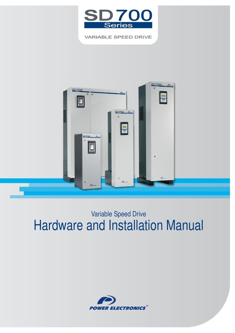
  9. Power Electronics SD700 Series User manual

Power Electronics SD700 Series User manual

Variable Speed Drive
Hardware and Installation Manual
Variable Speed Drive
Hardware and Installation Manual
Edition: March 2013
SD7KMTHW01BI Rev. B
SD700 KOMPAKT
POWER ELECTRONICS
2
POWER ELECTRONICS
SD700 KOMPAKT
3
SAFETY SYMBOLS
Always follow safety instructions to prevent accidents and potential hazards from occurring.
Edition of March 2013
This publication could present technical imprecision or misprints. The information here included will be
periodically modified and updated, and all those modifications will be incorporated in later editions.
To consult the most updated information of this product you might access through our website
www.power-electronics.com where the latest version of this manual can be downloaded.
WARNING
This symbol means improper operation may results in serious personal
injury or death.
CAUTION
Identifies shock hazards under certain conditions.Particular attention should
be given because dangerous voltage may be present. Maintenance
operation should be done by qualified personnel.
Identifies potential hazards under certain conditions. Read the message and
follow the instructions carefully.
Identifies shock hazards under certain conditions.Particular attention should
be given because dangerous voltage may be present.
SD700 KOMPAKT
POWER ELECTRONICS
4
Revisions
Date Revision Description
08 / 06 / 2010 A First edition
11 / 03 / 2013 B Transportation. EMC installation requirements. Installation
recommendations. STO board safety function. ATEX. Multipulse
drive connection. CE marking. Control cooling.
POWER ELECTRONICS
SD700 KOMPAKT
INDEX
5
INDEX
SAFETY INSTRUCTIONS........................................................................................................... 7
1. INTRODUCTION .................................................................................................................. 11
2. CONFIGURATION TABLE AND STANDARD RATINGS.................................................... 12
2.1. Configuration Table.................................................................................................... 12
2.2. Standard Ratings –230Vac....................................................................................... 12
2.3. Standard Ratings –400Vac....................................................................................... 13
2.4. Standard Ratings –440Vac....................................................................................... 13
2.5. Standard Ratings –500Vac....................................................................................... 14
2.6. Standard Ratings –525Vac....................................................................................... 14
2.7. Standard Ratings –690vac........................................................................................ 15
3. TECHNICAL CHARACTERISTICS...................................................................................... 16
4. RECEPTION, HANDLING AND TRANSPORTATION......................................................... 19
4.1. Reception and Storage .............................................................................................. 19
4.2. Handling and Transportation...................................................................................... 19
5. MECHANICAL INSTALLATION .......................................................................................... 21
5.1. Environmental Ratings............................................................................................... 21
5.2. Drive Mounting........................................................................................................... 22
5.3. Tables of Heat Dissipation......................................................................................... 26
6. POWER CONNECTION....................................................................................................... 27
6.1. Basic configuration..................................................................................................... 27
6.2. Topology.................................................................................................................... 28
6.3. Power Connection and Wiring.................................................................................... 29
6.4. Ground connection..................................................................................................... 33
6.5. EMC Installation Requirements.................................................................................. 34
6.6. Protections................................................................................................................. 36
6.7. IT grids –floating earth drives.................................................................................... 36
6.8. Power Terminals........................................................................................................ 37
7. CONTROL CONNECTION................................................................................................... 41
7.1. Wiring recommendations ........................................................................................... 41
7.2. Control board terminals description............................................................................ 42
7.3. STO –Safe Torque Off.............................................................................................. 45
7.4. Connection with ATEX motors ................................................................................... 49
8. MODBUS COMMUNICATION.............................................................................................. 50
8.1. Introduction................................................................................................................ 50
8.2. Hardware ................................................................................................................... 51
8.3. RS232 Connections................................................................................................... 52
8.4. RS485 Connections................................................................................................... 52
9. COMMISSIONING................................................................................................................ 53
10. DIMENSIONS....................................................................................................................... 55
10.1. Dimensions IP00........................................................................................................ 55
10.2. Dimensions IP20........................................................................................................ 57
11. INDUCTANCES.................................................................................................................... 59
11.1. Inductances for SD700 KOMPAKT Drive................................................................... 59
11.2. Dimensions of Inductances........................................................................................ 61
12. MAINTENANCE ................................................................................................................... 66
12.1. Warnings.................................................................................................................... 66
12.2. Routine Inspection ..................................................................................................... 66
SD700 KOMPAKT
POWER ELECTRONICS
6
INDEX
13. OPTIONAL EQUIPMENT..................................................................................................... 68
13.1. Accessories................................................................................................................ 68
13.2. IP20 Housing ............................................................................................................. 69
13.3. Communication boards.............................................................................................. 69
13.4. Dynamic Braking Unit B150....................................................................................... 70
13.5. Touch-Graphic Display............................................................................................... 71
14. CE MARKING....................................................................................................................... 72
14.1. EMC Directive............................................................................................................ 72
14.2. Low Voltage Directive ................................................................................................ 72
15. DECLARATION OF CONFORMITY CE............................................................................... 73
POWER ELECTRONICS
SD700 KOMPAKT
SAFETY INSTRUCTIONS
7
SAFETY INSTRUCTIONS
IMPORTANT!
Read this manual carefully to maximise the performance of this product and to ensure its safe use
and installation.
Power Electronics accepts no responsibility or liability for any damage resulting from
inappropriate use of the equipment.
In this manual, safety messages are classified as follows:
WARNING
Do not remove the metal cover while the power is applied or the unit is in operation.
Otherwise electric shock could occur.
Do not run the drive with the front cover removed.
Otherwise, you may get an electric shock due to the high voltage terminals or exposure of charged
capacitors.
Do not remove the cover except for periodic inspections or wiring, even if the input power is not
applied.
Otherwise, you may access the charged circuits and get an electric shock.
Wiring and periodic inspections should be performed at least 10 minutes after disconnecting the
input power. To remove the front cover check that the DC Link red LED is off, then remove the
terminals metallic cover and check with a multimeter the following measures:
Measure between the output power busbars U, V, W and the cabinet and check that the
voltage is around 0V.
Measure that the DC link terminals +, - and chassis voltage are below 30VDC.
Otherwise, you may get an electric shock.
Operate the switches with dry hands. Otherwise, you may get an electric shock.
Do not use cables with damaged insulation. Otherwise, you may get an electric shock.
Do not subject the cables to abrasions, excessive stress, heavy loads or pinching. Otherwise, you
may get an electric shock.
Do not make any insulation or voltage withstand tests on the motor with the drive connected.
SD700 KOMPAKT
POWER ELECTRONICS
8
SAFETY INSTRUCTIONS
CAUTION
Install the drive on a non-flammable surface. Do not place flammable material nearby. Otherwise
fire could occur.
Disconnect the input power if the drive is damaged. Otherwise, it could result in a secondary accident
or fire.
After stopping the drive, it will remain hot for a couple of minutes. Touching hot parts may result in
skin burns.
Do not apply power to a damaged drive or to a drive with parts missing even if the installation is
complete. Otherwise, you may get an electric shock.
It is not permitted to weld the cabinet; this can damage the electronic sensitive equipment inside.
Do not allow lint, paper, wood chips, dust, metallic chips or other foreign matter into the drive.
Otherwise fire or accident could occur.
WARNINGS
RECEPTION
The SD700 are carefully tested and perfectly packed before delivering.
In the event of transport damage, please ensure that you notify the transport agency and POWER
ELECTRONICS: 902 40 20 70 (International +34 96 136 65 57) or your nearest agent, within 24hrs
from receipt of the goods.
UNPACKING
Make sure model and serial number of the variable speed drive are the same on the box, delivery
note and unit.
Each variable speed drive is delivered with Hardware and Software technical manuals.
RECYCLING
Packing of the equipments should be recycled. For this, it is necessary to separate different
materials included (plastic, paper, cardboard, wood ...) and deposit them on proper banks.
Waste products of electric and electronic devices should be selectively collected for your correct
recycling company.
ELECTROMAGNETIC COMPATIBILITY (EMC)
The drive is intended to be used in industrial environment (Second Environment), it achieve
compliance with C3 category defined in IEC/EN 61800-3 standard following the installation
recommendation within this manual.
Select communication and control system according to the drive EMC environment. Otherwise,
systems could suffer from interferences due to a low EMS level.
POWER ELECTRONICS
SD700 KOMPAKT
SAFETY INSTRUCTIONS
9
SAFETY
Before operating the drive, read this manual thoroughly to gain and understanding of the unit. If
any doubt exists then please contact POWER ELECTRONICS, (902 40 20 70 / +34 96 136 65
57) or your nearest agent.
Wear safety glasses when operating the drive with power applied or the front cover is removed.
Handle and transport the drive following the recommendations within this manual.
Install the drive according to the instructions within this manual and the local regulations.
Do not place heavy objects on the drive.
Ensure that the drive is mounted vertically and keeping the minimum clearances distances.
Do not drop the drive or subject it to impact.
The SD700 Kompakt drives contain static sensitive printed circuits boards. Use static safety
procedures when handling these boards.
Avoid installing the drive in conditions that differ from those described in the Environmental
Ratings section.
CONNECTION PRECAUTIONS
To ensure correct operation of the drive it is recommended to use a SCREENED CABLE for the
control wiring.
The motor cable should comply with the requirements within this manual. Due to increased
leakage capacitance between conductors, external ground fault protection threshold value
should be adjusted ad hoc.
Do not disconnect motor cables if input power supply remains connected.
The internal circuits of the SD700 Kompakt Series will be damaged if the incoming power is
connected and applied to output terminals (U, V, W).
Do not use power factor correction capacitors banks, surge suppressors, or RFI filters on the
output side of the drive. Doing so may damage these components.
Always check whether the DC Link red LED is OFF before wiring terminals. The capacitors may
hold high-voltage even after the input power is disconnected.
TRIAL RUN
Verify all parameters before operating the drive. Alteration of parameters may be required
depending on application and load.
Always apply voltage and current signals to each terminal that are within levels indicated within
this manual.
OPERATION PRECAUTIONS
When the Auto Restart function is enabled, keep clear of driven equipment, as the motor will
restart suddenly after the fault reset.
The “STOP / RESET” key on the keypad is active only if the appropriate function setting has
been made. Pushing this button the drive will NOT perform a safe stop. It is available STO
optional board, which installed with a separate EMERGENCY pushbutton, will disconnect the
power and will be unable to generate torque in the motor with high reliability.
If a fault is reset with the reference signal still active, the drive will unexpectedly restart. Verify
that it is permissible for this to happen. Otherwise, it may lead to injury to people.
Do not modify or alter internal wiring and spare parts without Power Electronics supervision.
Before programming or operating the SD700 Kompakt Series, initialise all parameters back to
factory default values.
SD700 KOMPAKT
POWER ELECTRONICS
10
SAFETY INSTRUCTIONS
EARTH CONNECTION
Ground the drive and adjoining cabinets to ensure a safety operation and to reduce
electromagnetic emission.
Connect the input PE terminal only to the dedicated PE terminal of the drive. Do not use the
case or the chassis screw for grounding.
Ground the drive chassis through the dedicated and labelled terminals. Use appropriate
conductors to comply with the local regulations. The ground conductor should be connected first
and removed last.
Motor ground cable must be connected to the PE output terminal of the drive and not to the
installation’s ground. We recommend that the section of the ground conductor (PE) should be
equal or greater than the active conductor (U, V, W).
If the user decides to use shielded motor cable, ensure a correct 360º shield bonding in both the
drive cabinet and the motor terminal box.
HOW TO USE THIS MANUAL
Quick Guide
1- Make sure model and serial number of the drive are the same on the delivery note and unit. See
Chapter 2.
2- Read carefully the safety instructions before installation, commissioning, operation and
maintenance of the drive. See safety instructions section.
3- For reception, handling and transportation see Chapter 4.
4- Before the mechanical installation, check the environmental ratings, drive configuration mounting
and clearances. See chapter 5.
5- Follow the mechanical installation instructions. See Chapter 5.
6- Before the electrical installations, check basic configuration and wiring recommendations, see
Chapter 6 and Chapter 7.
7- Follow the electrical installation instructions in Chapter 6 and Chapter 7.
8- For Modbus Communication hardware, see Chapter 8.
9- Follow the commissioning instructions in Chapter 9.
10- For preventive maintenance instructions, follow the recommendations in Chapter 12.
POWER ELECTRONICS
SD700 KOMPAKT
INTRODUCTION
11
1. INTRODUCTION
SD700 low voltage drives by Power Electronics is the most extensive product family with a power range
from 1.5kW to 2000kW. It has been designed focused on maximum motor care, components durability and
easy maintenance. SD700 portfolio is divided in 3 products series that comply with specific demands and
standards in worldwide installations thanks to its own specific features: SD700, SD700KOMPAKT,
SD700FREEMAQ (SD700FR & SD700FL).
The SD700 Kompakt series with a power density up to 800kW/m³ is the suitable solution when space
saving is necessary. The drive keeps the advanced family features reducing up to 2.5 times the size. This
series is available from 63kW to 800kW with a voltage range from 230VAC to 690VAC and is available for
6 and 12 pulses. It is delivered in two IP00 pieces, the drive unit and separately the input chokes, and can
be easily adapted to IP20. The customer, following Power Electronics' recommendations, will easily install
the components in a dedicated cabinet or technical room.
The whole family integrates unique features such as low dV/dt, smart mechanical design and accurate
control.
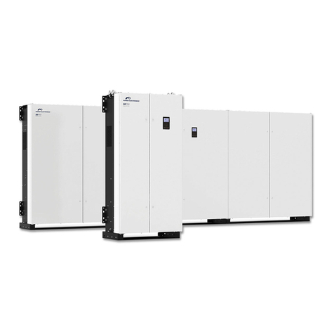
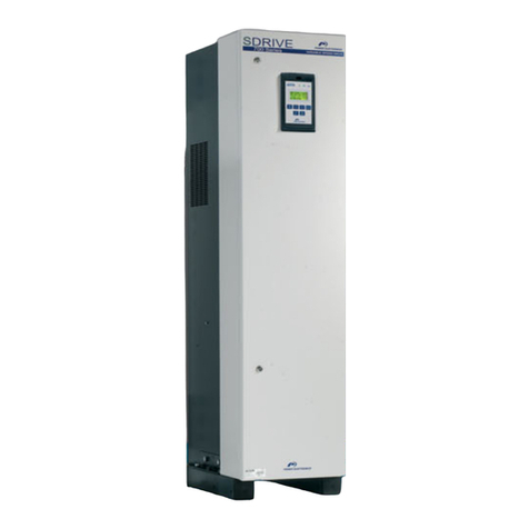
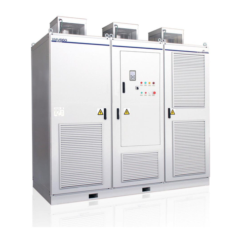
Figure 1.1 SD700 Kompakt Series
SD700 products provide high efficiency, maximum control, functional safety, durability, easy
commissioning and easy maintenance for the whole range. Power Electronics delivers flexible integrated
solutions, fully tested under the most demanding environmental and electrical conditions.
SD700 KOMPAKT
POWER ELECTRONICS
12
CONFIGURATION TABLE AND STANDARD RATINGS
2. CONFIGURATION TABLE AND STANDARD
RATINGS
2.1. Configuration Table
EXAMPLE
CODE: SD7K037050121T
SD7K
0370
5
0
12
1
T
-
SD700
KOMPAKT
Series
Output
Current [1]
Input
Voltage
Protection
Degree
Pulse
Number
Filter
Floating
Earth
Input
Frequency
0370
370A
2
230VAC
0
IP00
-
6 Pulse
-
2nd
Environment
-
Without
floating
earth
-
50Hz
0460
460A
5
380-
500VAC
2
IP20
12
12 Pulse
F
1st
Environment [2]
T
With
floating
earth
6
60Hz [3]
...
...
7
525VAC
6
690VAC
GENERAL CONSIDERATIONS:
[1] Verify the rated current of the motor nameplate to guarantee the compatibility with the selected drive.
[2] Floating earth drive not available with first environment filter.
[3] Consult availability.
Examples: SD7K037052 - SD700 Kompakt, 370A, 400VAC, Protection Degree IP20, 6 pulses, Environment 2
SD7K092550 - SD700 Kompakt, 925A, 400VAC, Protection Degree IP00, 6 pulses, Environment 2
SD70720201 - SD700 Kompakt, 720A, 230VAC, Protection Degree IP00, 6 pulses, Environment 1
2.2. Standard Ratings –230Vac
6 PULSES
FRAME
CODE
Operation Temperature 50ºC
HEAVY DUTY
Operation Temperature 40ºC
NORMAL DUTY
I(A) Rated
Motor
Power (kW)
at 230VAC
150%
Overload
(A)
I(A) Rated
Motor
Power (kW)
at 230VAC
120%
Overload
(A)
1
SD7K0210 2X Y
210
63
315
263
75
315
SD7K0250 2X Y
250
75
375
313
75
375
SD7K0275 2X Y
275
75
413
344
100
413
2
SD7K0330 2X Y
330
100
495
413
110
495
SD7K0370 2X Y
370
110
555
463
140
555
SD7K0460 2X Y
460
140
690
575
185
690
3
SD7K0580 2X Y
580
185
870
725
200
870
SD7K0650 2X Y
650
200
975
813
220
975
SD7K0720 2X Y
720
220
1080
900
250
1080
POWER ELECTRONICS
SD700 KOMPAKT
CONFIGURATION TABLE AND STANDARD RATINGS
13
2.3. Standard Ratings –400Vac
6 PULSES
FRAME
CODE
Operation Temperature 50ºC
HEAVY DUTY
Operation Temperature 40ºC
NORMAL DUTY
I(A)
Rated
Motor
Power (kW)
at 400VAC
150%
Overload
(A)
I(A)
Rated
Motor
Power (kW)
at 400VAC
120%
Overload
(A)
1
SD7K0210 5X Y
210
110
315
263
132
315
SD7K0250 5X Y
250
132
375
313
160
375
SD7K0275 5X Y
275
150
413
344
200
413
2
SD7K0330 5X Y
330
160
495
413
220
495
SD7K0370 5X Y
370
200
555
463
250
555
SD7K0460 5X Y
460
250
690
575
315
690
3
SD7K0580 5X Y
580
315
870
725
400
870
SD7K0650 5X Y
650
355
975
813
450
975
SD7K0720 5X Y
720
400
1080
900
500
1080
4
SD7K0840 5X Y
840
450
1260
1050
560
1260
SD7K0925 5X Y
925
500
1388
1156
630
1388
SD7K0990 5X Y
990
560
1485
1238
710
1485
12 PULSES
FRAME
CODE
Operation Temperature 50ºC
HEAVY DUTY
Operation Temperature 40ºC
NORMAL DUTY
I(A)
Rated
Motor
Power (kW)
at 400VAC
150%
Overload
(A)
I(A)
Rated
Motor
Power (kW)
at 400VAC
120%
Overload
(A)
4
SD7K0840 5X 12 Y
840
450
1260
1050
560
1260
SD7K0925 5X 12 Y
925
500
1388
1156
630
1388
SD7K0990 5X 12 Y
990
560
1485
1238
710
1485
2.4. Standard Ratings –440Vac
6 PULSES
FRAME
CODE
Operation Temperature 50ºC
HEAVY DUTY
Operation Temperature 40ºC
NORMAL DUTY
I(A)
Rated
Motor
Power (kW)
at 440VAC
150%
Overload
(A)
I(A)
Rated
Motor
Power (kW)
at 440VAC
120%
Overload
(A)
kW
HP
kW
HP
1
SD7K0210 5X Y
191
110
150
286,5
238,7
132
180
286,5
SD7K0250 5X Y
227
132
180
340,5
283,7
160
240
340,5
SD7K0275 5X Y
250
150
200
375
312,5
200
275
375
2
SD7K0330 5X Y
300
160
240
450
375
220
300
450
SD7K0370 5X Y
336
200
275
504
420
250
340
504
SD7K0460 5X Y
418
250
340
627
522,5
315
400
627
3
SD7K0580 5X Y
527
315
400
790,5
658,7
400
500
790,5
SD7K0650 5X Y
591
355
450
886,5
738,7
450
600
886,5
SD7K0720 5X Y
654,5
400
500
981,7
818,1
500
650
981,7
4
SD7K0840 5X Y
764
450
600
1146
955
560
750
1146
SD7K0925 5X Y
841
500
650
1261,5
1051,2
630
850
1261,5
SD7K0990 5X Y
900
560
750
1350
1125
710
900
1350
SD700 KOMPAKT
POWER ELECTRONICS
14
CONFIGURATION TABLE AND STANDARD RATINGS
12 PULSES
FRAME
CODE
Operation Temperature 50ºC
HEAVY DUTY
Operation Temperature 40ºC
NORMAL DUTY
I(A)
Rated
Motor
Power (kW)
at 440VAC
150%
Overload
(A)
I(A)
Rated
Motor
Power (kW)
at 440VAC
120%
Overload
(A)
kW
HP
kW
HP
4
SD7K0840 5X 12 Y
764
450
600
1146
955
560
750
1146
SD7K0925 5X 12 Y
841
500
650
1261,5
1051,2
630
850
1261,5
SD7K0990 5X 12 Y
900
560
750
1350
1125
710
900
1350
2.5. Standard Ratings –500Vac
6 PULSES
FRAME
CODE
Operation Temperature 50ºC
HEAVY DUTY
Operation Temperature 40ºC
NORMAL DUTY
I(A)
Rated
Motor
Power (kW)
at 500VAC
150%
Overload
(A)
I(A)
Rated
Motor
Power (kW)
at 500VAC
120%
Overload
(A)
1
SD7K0210 5X Y
168
110
252
210
132
252
SD7K0250 5X Y
200
132
300
250
150
300
SD7K0275 5X Y
212
150
318
265
160
318
2
SD7K0330 5X Y
264
160
396
330
200
396
SD7K0370 5X Y
296
200
444
370
250
444
SD7K0460 5X Y
368
250
552
460
315
552
3
SD7K0580 5X Y
464
315
696
580
355
696
SD7K0650 5X Y
520
355
780
650
400
780
SD7K0720 5X Y
576
400
864
720
450
864
4
SD7K0840 5X Y
672
450
1008
840
500
1008
SD7K0925 5X Y
740
500
1110
925
560
1110
SD7K0990 5X Y
767
560
1151
959
630
1151
12 PULSES
FRAME
CODE
Operation Temperature 50ºC
HEAVY DUTY
Operation Temperature 40ºC
NORMAL DUTY
I(A)
Rated
Motor
Power (kW)
at 500VAC
150%
Overload
(A)
I(A)
Rated
Motor
Power (kW)
at 500VAC
120%
Overload
(A)
4
SD7K0840 5X 12 Y
672
450
1008
840
500
1008
SD7K0925 5X 12 Y
740
500
1110
925
560
1110
SD7K0990 5X 12 Y
767
560
1151
959
630
1151
2.6. Standard Ratings –525Vac
6 PULSES
FRAME
CODE
Operation Temperature 50ºC
HEAVY DUTY
Operation Temperature 40ºC
NORMAL DUTY
I(A)
Rated
Motor
Power (kW)
at 525VAC
150%
Overload
(A)
I(A)
Rated
Motor
Power (kW)
at 525VAC
120%
Overload
(A)
1
SD7K0180 7X Y
180
132
270
222
150
270
SD7K0205 7X Y
205
150
308
254
185
308
2
SD7K0270 7X Y
270
200
405
334
250
405
SD7K0295 7X Y
295
220
443
360
280
443
SD7K0340 7X Y
340
250
510
417
315
510
3
SD7K0425 7X Y
425
315
638
526
400
638
SD7K0470 7X Y
470
355
705
586
450
705
SD7K0535 7X Y
535
400
803
666
500
803
4
SD7K0660 7X Y
660
500
990
824
600
990
SD7K0750 7X Y
750
560
1125
936
700
1125
POWER ELECTRONICS
SD700 KOMPAKT
CONFIGURATION TABLE AND STANDARD RATINGS
15
12 PULSES
FRAME
CODE
Operation Temperature 50ºC
HEAVY DUTY
Operation Temperature 40ºC
NORMAL DUTY
I(A)
Rated
Motor
Power (kW)
at 525VAC
150%
Overload
(A)
I(A)
Rated
Motor
Power (kW)
at 525VAC
120%
Overload
(A)
4
SD7K0660 7X 12 Y
660
500
990
824
600
990
SD7K0750 7X 12 Y
750
560
1125
936
700
1125
2.7. Standard Ratings –690Vac
6 PULSES
FRAME
CODE
Operation Temperature 50ºC
HEAVY DUTY
Operation Temperature 40ºC
NORMAL DUTY
I(A)
Rated
Motor
Power (kW)
at 690VAC
150%
Overload
(A)
I(A)
Rated
Motor
Power (kW)
at 690VAC
120%
Overload
(A)
1
SD7K0130 6X Y
130
110
195
163
132
195
SD7K0150 6X Y
150
132
225
188
160
225
SD7K0170 6X Y
170
160
255
213
200
255
2
SD7K0210 6X Y
210
200
315
263
250
315
SD7K0260 6X Y
260
250
390
325
315
390
SD7K0320 6X Y
320
315
480
400
355
480
3
SD7K0385 6X Y
385
355
578
481
450
578
SD7K0460 6X Y
460
450
690
575
500
690
4
SD7K0550 6X Y
550
500
825
688
630
825
SD7K0660 6X Y
660
630
990
825
800
990
12 PULSES
FRAME
CODE
Operation Temperature 50ºC
HEAVY DUTY
Operation Temperature 40ºC
NORMAL DUTY
I(A)
Rated
Motor
Power (kW)
at 690VAC
150%
Overload
(A)
I(A)
Rated
Motor
Power (kW)
at 690VAC
120%
Overload
(A)
4
SD7K0550 6X 12 Y
550
500
825
688
630
825
SD7K0660 6X 12 Y
660
630
990
825
800
990
SD700 KOMPAKT
POWER ELECTRONICS
16
TECHNICAL CHARACTERISTICS
3. TECHNICAL CHARACTERISTICS
SD700 Kompakt
INPUT
POWER RANGE [1]
63kW - 800 kW
VOLTAGE POWER
230Vac, 380-500Vac, 525Vac, 690Vac, 3 phases (±10%)
MULTIPULSE
6, 12
INPUT FREQUENCY
50Hz/60Hz ±6%
INPUT RECTIFIER TECHNOLOGY
Thyristor-Diode
DISPLACEMENT POWER FACTOR
(DPF = cos Φ )
0.98
POWER FACTOR (PF= I1/Irms· cos Φ)
0.91
MOMENTARY POWER LOSS
> 2sec (depending on the load inertia)
EMC INPUT FILTER
Second environment (Industrial): (C3 Standard)
First environment (Domestic): C2 (Optional). C1 consult with Power Electronics
Optional IT filter
HARMONICS FILTER
Choke coils 3% impedance
CURRENT THD (%)
≤ 40%
REGENERATIVE
NO
OUTPUT
OUTPUT FREQUENCY [2]
0... 200% of the nominal motor frequency (Hz)
OVERLOAD CAPACITY
Constant torque/heavy duty: 150% during 60 sec at 50ºC
Variable torque/normal duty: 120% during 60 sec at 40ºC.
EFFICIENCY (At rated current and
voltage)
≥98%
CONTROL METHOD
V/Hz
VECTOR CONTROL
Open Loop: PMC: speed (OLSP)/torque control (OLTQ), AVC: speed (OLSP)/torque control
(OLTQ).
Close Loop (Encoder): speed (CLSP)/torque control (CLTQ), AVC: speed (CLSP)/torque
control (CLTQ).
SWITCHING FREQUENCY
4 to 8kHz –PEWave
OUTPUT DV/DT FILTER
500 to 800V/µs
OUTPUT CABLE LENGTH [3]
USC150m
SC 75m
DYNAMIC BRAKE
External B150 Dynamic Brake
ENVIRONMENTAL
CONDITIONS
OPERATION AMBIENT
TEMPERATURE
Minimum: -20°C Maximum: +50°C
STORAGE TEMPERATURE
Minimum: -40°C Maximum: +70°C
ALTITUDE
1000m
POWER ALTITUDE DERATING [1]
>1000m, 1% PN(kW) per 100m; 3000m max
AMBIENT HUMIDITY
<95%, non-condensing
DEGREE OF PROTECTION
IP00, IP20
VIBRATION
DEFLECTION
0.075mm at 10Hz-57Hz
ACCELERATION
9.8m/s² at 57Hz-150Hz
HEATING RESISTORS
Optional
PROTECTIONS
MOTOR PROTECTIONS
Rotor locked, Motor Overload (thermal model), Output current limit, Phase current imbalance,
Phase voltage imbalance, Motor over-temperature (PTC signal), Speed limit, Torque limit.
DRIVE PROTECTIONS
IGBT's overload, Input phase loss, Low input voltage, High input voltage, DC Bus voltage limit,
Low DC Bus voltage, High input frequency, Low input frequency, IGBT temperature, Heat-sink
over-temperature, Power supply fault, Drive thermal model, Ground fault, Software and
Hardware fault, Analogue input signal loss (speed reference loss), Safe stop / Emergency stop.
[1] Other configuration, consult Power Electronics.
[2] For operation frequencies higher than 100Hz consult Power Electronics.
[3] SC: Shielded cable, USC: Unshielded Cable. Follow Power Electronics installation recommendations. For greater cable lengths consult with
Power Electronics.
POWER ELECTRONICS
SD700 KOMPAKT
TECHNICAL CHARACTERISTICS
17
SD700 Kompakt
HARDWARE
DIGITAL INPUTS
6 programmable
Active high (24Vdc), 1 PTC input, Isolated power supply
DIGITAL OUTPUTS
3 Programmable changeover relays (250Vac, 8A or 30Vdc, 8A)
ANALOGUE INPUTS
2 Programmable differential inputs: 0 –20mA, 4 –20mA, 0 –10Vdc and 10Vdc.
Optically isolated.
ANALOGUE OUTPUTS
2 Isolated programmable outputs: 0 –20mA, 4 –20mA, 0 –10Vdc and 10Vdc
ENCODER INPUTS (Optional)
Two differential encoders input. Voltages inputs from 5 to 24Vdc
USER POWER SUPPLY
+24Vdc user power supply (Max 180mA) regulated and short-circuit protected
+10Vdc user power supply (Max 2 potentiometers R= 1k ) regulated and short-circuit
protected
I/O EXTENSION BOARD (Optional)
4 Digital Inputs: Programmable inputs and active high (24Vdc). Optically isolated.
1 Analogue Input: Programmable and differential input.
5 Digital Outputs: Programmable multi-function relays.
1 Analogue Output: Programmable outputs in voltage / current.
EXTERNAL POWER SUPPLY
(Optional)
24V External Power Supply, Fault Relay integrated
COMMUNICATION
STANDARD HARDWARE
USB port
RS232 port
RS485 port
OPTIONAL HARDWARE
Optical fiber
Ethernet
STANDARD PROTOCOL
Modbus-RTU
OPTIONAL PROTOCOL
Profibus-DP
DeviceNet
Ethernet (Modbus TCP)
Ethernet IP
CAN Open
N2 Metasys Gateway
CONTROL PANEL
TYPE
Removable
LENGTH
3 meters and 5 meters (optional)
CONNECTION
RJ45
VISUALIZATION LEDS
LED ON: Control board is energized
LED RUN: Motor receiving power supply
LED FAULT: Flashing displays that a fault has occurred
ALPHANUMERIC DISPLAY
4 lines x 16 characters
Keypad with 6 keys to control and configure the drive, start and stop/reset
Independent memory
COLOUR TOUCH-SCREEN DISPLAY
(Optional)
3.5‟‟ Touch Screen (240x320 pixels) with pen
4Gb MicroSD card | Faults and events log and notification
Quad Band GSM modem integrated to remote start, stop and notification by SMS
Ethernet Switch with two RJ45 connections
Optional 5Vdc external power supply or batteries
DISPLAY INFORMATION
Average current and 3-phase motor current
Average voltage and 3-phase motor voltage
Average input voltage and 3-phase input voltage
3-phase input and output frequency
DC Bus Voltage
Drive Status
Speed, Torque, Power, Power factor of motor
Register of total and partial drive running time with reset function. (hours)
Register of total and partial drive energy consumption with reset function (kWh)
Relay status
Digital inputs / PTC status
Output comparator status
Analogue inputs and sensor values
Analogue output value
Motor overload and equipment status
Drive and rectifier temperature
Fault history (last 6 faults)
OTHERS
Real time clock
Perpetual calendar
SD700 KOMPAKT
POWER ELECTRONICS
18
TECHNICAL CHARACTERISTICS
SD700 Kompakt
REGULATIONS
CERTIFICATIONS
CE, cTick, UL [4], cUL [4]
ELECTROMAGNETIC
COMPATIBILITY
EMC Directive (2004/108/CE)
IEC/EN 61800-3
DESIGN AND CONSTRUCTION
LVD Directive (2006/95/CE)
IEC/EN 61800-2 General requirements
IEC/EN 61800-5-1 Safety
IEC/EN 60146-1-1 Semiconductor converters
IEC 60068-2-6 Vibration
FUNCTIONAL SAFETY
IEC/EN 61800-5-2 (STO) certified by Tüv Rheinland
[4] On certification process.

Other manuals for SD700 Series

8

This manual suits for next models

5

Other Power Electronics DC Drive manuals

Power Electronics SD 500 Series User manual

Power Electronics

Power Electronics SD 500 Series User manual

Power Electronics XMV660 Series Manual

Power Electronics

Power Electronics XMV660 Series Manual

Power Electronics SD700 Series User manual

Power Electronics

Power Electronics SD700 Series User manual

Power Electronics SD 300 Series Parts list manual

Power Electronics

Power Electronics SD 300 Series Parts list manual

Power Electronics SD750 Series User manual

Power Electronics

Power Electronics SD750 Series User manual

Power Electronics SD750 Series User manual

Power Electronics

Power Electronics SD750 Series User manual

Power Electronics SD 500 Series Parts list manual

Power Electronics

Power Electronics SD 500 Series Parts list manual

Power Electronics SD750 Series User manual

Power Electronics

Power Electronics SD750 Series User manual

Power Electronics SD 300 Series User manual

Power Electronics

Power Electronics SD 300 Series User manual

Power Electronics SD700 Series Instructions for use

Power Electronics

Power Electronics SD700 Series Instructions for use

Power Electronics SD750 Series User manual

Power Electronics

Power Electronics SD750 Series User manual

Power Electronics SD750SP User manual

Power Electronics

Power Electronics SD750SP User manual

Power Electronics SD450 Series User manual

Power Electronics

Power Electronics SD450 Series User manual

Power Electronics SD750 Series User manual

Power Electronics

Power Electronics SD750 Series User manual

Power Electronics VFD User manual

Power Electronics

Power Electronics VFD User manual

Power Electronics SD750K User manual

Power Electronics

Power Electronics SD750K User manual

Power Electronics SD750 Series User manual

Power Electronics

Power Electronics SD750 Series User manual

Power Electronics SD700SP Series User manual

Power Electronics

Power Electronics SD700SP Series User manual

Power Electronics SD 500 Series User manual

Power Electronics

Power Electronics SD 500 Series User manual

Power Electronics B150 Series Operator's manual

Power Electronics

Power Electronics B150 Series Operator's manual

Power Electronics SD 500 Series User manual

Power Electronics

Power Electronics SD 500 Series User manual

Power Electronics SD750 Series User manual

Power Electronics

Power Electronics SD750 Series User manual

Power Electronics SDRIVE 700 Series Parts list manual

Power Electronics

Power Electronics SDRIVE 700 Series Parts list manual

Power Electronics SD300312 User manual

Power Electronics

Power Electronics SD300312 User manual

Popular DC Drive manuals by other brands

Allen-Bradley PowerFlex 525 Application Technique

Allen-Bradley

Allen-Bradley PowerFlex 525 Application Technique

Drivecon XT Series Service manual

Drivecon

Drivecon XT Series Service manual

THORLABS MTS25-Z8 Original instructions

THORLABS

THORLABS MTS25-Z8 Original instructions

HP Ultrium Drive Configuration guide

HP

HP Ultrium Drive Configuration guide

Aerotech Automation1 iXC2 Hardware manual

Aerotech

Aerotech Automation1 iXC2 Hardware manual

Aura FIREBALL-8 owner's manual

Aura

Aura FIREBALL-8 owner's manual

EACON EC590 Series quick guide

EACON

EACON EC590 Series quick guide

TR-Electronic encoTRive MP Series user manual

TR-Electronic

TR-Electronic encoTRive MP Series user manual

Nidec Digitax ST Series installation guide

Nidec

Nidec Digitax ST Series installation guide

Siemens Sinamics S120M Equipment manual

Siemens

Siemens Sinamics S120M Equipment manual

YASKAWA HV600 Installation & Startup

YASKAWA

YASKAWA HV600 Installation & Startup

Lenze EZAMBHXX028 Mounting instructions

Lenze

Lenze EZAMBHXX028 Mounting instructions

Eaton DA1-32030-20 Series Instruction leaflet

Eaton

Eaton DA1-32030-20 Series Instruction leaflet

SOMFY ALTUS 40 RTS instructions

SOMFY

SOMFY ALTUS 40 RTS instructions

YASKAWA JVOP-181 Driver installation guide

YASKAWA

YASKAWA JVOP-181 Driver installation guide

Masterflex I/P MFLX07591-20 operating manual

Masterflex

Masterflex I/P MFLX07591-20 operating manual

Aerotech MPS75SV Hardware manual

Aerotech

Aerotech MPS75SV Hardware manual

Aerotech Automation1 iXL2e Hardware manual

Aerotech

Aerotech Automation1 iXL2e Hardware manual

manuals.online logo
manuals.online logoBrands
  • About & Mission
  • Contact us
  • Privacy Policy
  • Terms and Conditions

Copyright 2025 Manuals.Online. All Rights Reserved.