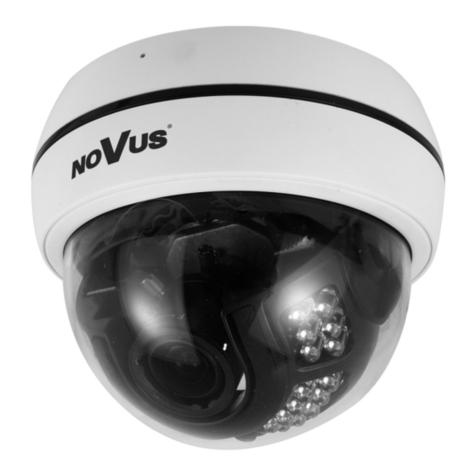
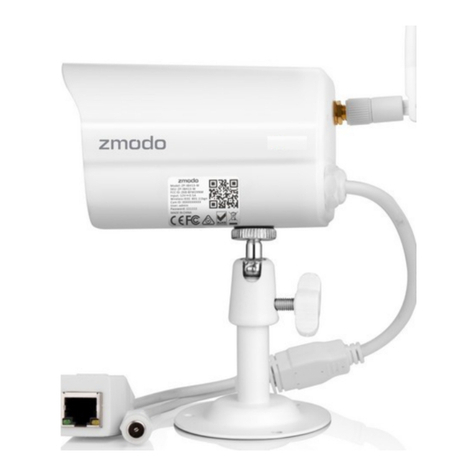
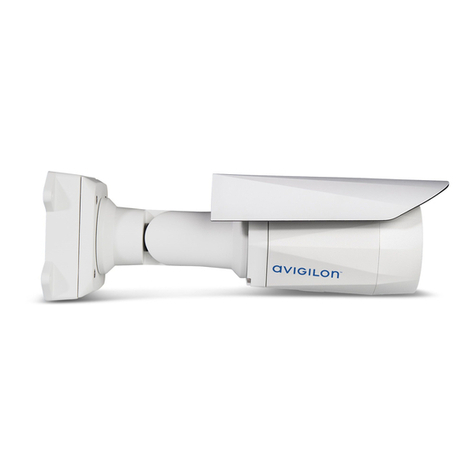
EuropeVision EVS-ABD1300 User manual

Before attempting to connect or operate this product,
please read these instructions carefully and save this manual for future use.
User's Manual
EVS-ABD1300, EVS-ABL1300, EVS-ADR1300
EVS1300V10-A

© 2017 Europe Vision Systems s.r.o. All rights reserved.
Under the copyright laws, this manual may not be copied, in whole or in part,
without the written consent of Europe Vision.
Every effort has been made to ensure that the information in this manual is
accurate. Europe Vision makes no expressed or implied warranty of any kind
and assumes no responsibility for errors or omissions. No liability is assumed
for incidental or consequential damages arising from the use of the information
or products contained herein. Features and specifications are subject to
change without notice.
Note: No memory card slot or local storage function for Argentina.
Europe Vision Systems s.r.o.
Pod vinicí 2028/20
143 01 Praha 4, Česká republika
Tel: +420-225-371-121
Fax: +420-225-371-131
Trademarks used in this manual: EuropeVision and the EuropeVision logo are
trademarks of Europe Vision Systems s.r.o. Windows is the registered
trademark of Microsoft Corporation.
January 2017

Preface
This Manual is designed for the following models and firmware versions:
Model Model Number Firmware Version
Eyeball Dome ABD1300
Bullet IP Camera ABL1300
Mini Fixed Rugged IP Dome ADR1300
V1.0
i

Contents
Naming Definition....................................................................iv
Note for Connecting to GV-VMS / DVR / NVR........................v
Note for Installing Camera Outdoor ......................................vi
Chapter 1 Introduction ..........................................................1
1.1 Key Features ......................................................................................................... 2
1.2 Packing List ........................................................................................................... 4
1.3 Optional Accessories............................................................................................. 5
Chapter 2 Accessing the Camera.........................................6
2.1 Installing on a Network........................................................................................... 6
2.1.1 Checking the Dynamic IP Address............................................................. 7
2.1.2 Assigning an IP Address............................................................................ 9
2.2 Accessing Live View.............................................................................................11
2.2.1 The Live View Window............................................................................12
Chapter 3 Administrator Mode ...........................................15
3.1 Common...............................................................................................................17
3.1.1 Basic Info..................................................................................................17
3.1.2 Local Settings...........................................................................................18
3.2 Network ................................................................................................................20
3.2.1 Network ....................................................................................................20
3.2.2 DNS..........................................................................................................22
3.2.3 Port...........................................................................................................23
3.2.4 FTP.........................................................................................................25
3.2.5 E-mail.......................................................................................................27
3.3 Video....................................................................................................................28
3.3.1 Video........................................................................................................28
3.3.2 Snapshot ..................................................................................................30
3.3.3 Media Stream...........................................................................................31
3.4 Image ...................................................................................................................33
3.4.1 Image .......................................................................................................33
3.4.2 OSD..........................................................................................................39
3.4.3 Privacy Mask...............................................................................................40
ii

iii
3.5 Events.....................................................................................................................41
3.5.1 Motion Detection.......................................................................................41
3.6 Storage ...................................................................................................................44
3.6.1 Storage.....................................................................................................44
3.7 Security.................................................................................................................46
3.7.1 User..........................................................................................................46
3.7.2 Network Security.......................................................................................47
3.8 System..................................................................................................................49
3.8.1 Time .........................................................................................................49
3.8.2 Maintenance.............................................................................................51
Chapter 4 Recording and Playback ...................................52
4.1 Recording.............................................................................................................52
4.2 Playback from the Memory Card...........................................................................53
4.2.1 Recording Download ................................................................................55
Chapter 5 Advanced Applications .....................................56
5.1 Upgrading System Firmware.................................................................................56
5.1.1 Using the Web Interface ...........................................................................57
5.1.2 Using the GV-IP Device Utility ..................................................................58
5.2 Restoring to Factory Default Settings....................................................................60
5.2.1 Using the Web Interface ...........................................................................60
5.2.2 Directly on the Camera.............................................................................61
Chapter 6 DVR Configurations...........................................62
6.1 Setting Up IP Cameras on GV-System .................................................................63
6.1.1 Customizing the Basic Settings on GV-System.........................................65
6.2 Setting Up IP Cameras on GV-VMS .....................................................................66
Appendix ………………………………………………………..68
A. RTSP Protocol Support.............................................................................................68
B. Optional Installation for ABD1300.............................................................................69
C. Optional Installation for ADR1300.............................................................................74
D. Optional Installation for ABL1300..............................................................................79

Naming Definition
GV-System GeoVision Analog and Digital Video Recording Software. The GV-
System also refers to Multicam System, GV-NVR System, GV-
DVR System and GV-Hybrid DVR System at the same time
GV-VMS GeoVision Video Management System for IP cameras.
iv

Note for Connecting to GV-VMS / DVR / NVR
The Eyeball Dome, Bullet IP Camera and Mini Fixed Rugged Dome are designed to work
with and record on GV-VMS / DVR / NVR, a video management system. Once the cameras
are connected to the GV-VMS / DVR / NVR, the resolution set on the GV-VMS / DVR / NVR
will override the resolution set on the cameras’ Web interface. You can only change the
resolution settings through the Web interface when the connection to the GV-VMS / DVR /
NVR is interrupted.
v

Note for Recording
Mind the following when using a memory card for recording:
1. Recorded data on the memory card can be damaged or lost if the data are accessed
while the camera is under physical shock, power interruption, memory card detachment
or when the memory card reaches the end of its lifespan. No guarantee is provided for
such causes.
2. The stored data can be lost if the memory card is not accessed for a long period of time.
Back up your data periodically if you seldom access the memory card.
3. Memory cards are expendable and their durability varies according to the conditions of
the installed site and how they are used. Back up your data regularly and replace the
memory card annually.
4. To avoid power outage, it is highly suggested to apply a battery backup (UPS).
5. For better performance, it is highly suggested to use Micro SD card of MLC NAND flash,
Class 10.
6. Replace the memory card when its read/write speed is lower than 6 MB/s or when the
memory card is frequently undetected by the camera.
vi

vii
Note for Installing Camera Outdoor
When installing the camera outdoor, be sure that:
1. The camera is set up above the junction box to prevent water from entering the camera
along the cables.
2. Any power, audio and I/O cables are waterproofed using waterproof silicon rubber or the
like.
3. The screws are tightened and the cover is in place after opening the camera cover.

Introduction
1
Chapter 1 Introduction
For ABD1300
The Eyeball Dome is an outdoor, network, camera equipped with an automatic IR-cut filter
and an IR LED for day and night surveillance. The camera adheres to IP66 standards.
For ABL1300
The Bullet Camera is an outdoor, network camera equipped with an automatic IR-cut filter
and 2 IR LEDs for day and night surveillance. The camera adheres to IP66 standards. The
Bullet Camera offers an entry-level surveillance solution with all the essential features at
excellent image quality.
For ADR1300
The Mini Fixed Rugged Dome is an outdoor, fixed, network camera equipped with an
automatic IR-cut filter and 30 IR LEDs for day and night surveillance. The camera adheres to
IP66 and IK10 standards.
1

1.1 Key Features
For ABD1300
1/3" progressive scan low lux CMOS sensor
Min. illumination at 0.06 lux (B/W and color)
Triple streams from H.264 and MJPEG
Up to 30 fps at 1280 x 960
Intelligent IR
IR distance up to 30 m (98.4 ft)
Day and night function (with removable IR-cut filter)
3-axis mechanism (pan / tilt / rotate)
Ingress protection (IP66)
Wide temperature tolerance (-35°C ~ 60°C / -31°F ~ 140°F)
DC 12V / PoE (IEEE 802.3af)
Wide Dynamic Range (WDR)
Defog
3D noise reduction
Motion detection
Text overlay
Privacy mask
ONVIF (Profile S) conformant
For ABL1300
1/3" progressive scan low lux CMOS sensor
Min. illumination at 0.06 lux (B/W and color)
Triple streams from H.264 and MJPEG
Up to 30 fps at 1280 x 960
Intelligent IR
IR distance up to 30 m (98.4 ft)
Day and night function (with removable IR-cut filter)
Ingress protection (IP66)
2

Introduction
1
Wide temperature tolerance (-35°C ~ 60°C / -31°F ~ 140°F)
DC 12V / PoE (IEEE 802.3af)
Wide Dynamic Range (WDR)
Defog
3D noise reduction
Motion detection
Text overlay
Privacy mask
ONVIF (Profile S) conformant
For ADR1300
1/3" progressive scan low lux CMOS sensor
Min. illumination at 0.02 lux (B/W and color)
Triple streams from H.264 and MJPEG
Up to 30 fps at 1280 x 960
Intelligent IR
IR distance up to 30 m (98.4 ft)
Day and night function (with removable IR-cut filter)
3-axis mechanism (pan / tilt / rotate)
Ingress protection (IP66)
Vandal resistance (IK10)
Wide temperature tolerance (-35°C ~ 60°C / -31°F ~ 140°F)
Built-in micro SD card slot (SD/SDHC/SDXC/UHS-I, Class 10) for local storage
DC 12V / PoE (IEEE 802.3af)
Wide Dynamic Range (WDR)
Defog
3D noise reduction
Motion detection
Text overlay
Privacy mask
ONVIF (Profile S) conformant
3

1.2 Packing List
For ABD1300
Eyeball Dome
Waterproof Rubber Set
Screw x 2
Screw Anchor x 2
Drill Template Paster
Software Download Guide
Warranty Card
For ABL1300
Bullet Camera
Waterproof Rubber Set
Screw x 5
Screw Anchor x 5
Drill Template Paster
Software Download Guide
Warranty Card
For ADR1300
Mini Fixed Rugged IP Dome
Waterproof Rubber Set
Screw x 3
Screw Anchor x 3
Drill Template Paster
Torx Wrench
Software Download Guide
Warranty Card
4

Introduction
5
1
1.3 Optional Accessories
Optional accessories can expand the capabilities and versatility of your cameras. Contact
your dealer for more information.
Model Number Name Details
GV-Mount211 Wall Mount Bracket
Dimensions: 233 x 126 x 126
mm (9.2” x 5” x 5”)
Weight: 0.92 kg (2.0 lb)
Only ABD1300 and ADR1300
support this accessory.
GV-Mount502 Wall Mount Bracket
Dimensions: 93 x 93 x 39 mm
(3.66” x 3.66” x 1.53”)
Weight: 0.235kg (0.52 lb)
Only ABL1300 supports this
accessory.
GV-PA191 Power over Ethernet
(PoE) Adapter
The GV-PA191 is a Power
over Ethernet (PoE) adapter
designed to provide power to
the IP device through a single
Ethernet cable.
GV-POE Switch The GV-POE Switch is designed to provide power
along with network connection for IP devices. The
GV-POE Switch is available in various models with
different numbers and types of ports.
Power Adapter Contact your sales representative for the countries
and areas supported.

Chapter 2 Accessing the Camera
Once installed, the camera is accessible on a network. Follow these steps to configure the
network settings and access your surveillance images.
2.1 Installing on a Network
These instructions describe the basic connections to install the camera on the network.
1. Using a standard network cable, connect the camera to your network.
2. Connect to power using one of the methods:
Using the optional power adapter to connect to power.
Using the Power over Ethernet (PoE) function. The power will be provided over the
network cable.
3. You can now access the Web interface of the camera.
If the camera is installed in a LAN with the DHCP server, use GV-IP Device Utility to
look up the camera’s dynamic IP address. See 2.1.1 Checking the Dynamic IP
Address.
If the camera is installed in a LAN without the DHCP server, the default IP address
192.168.0.10 will be applied. To assign a different static IP address, see 2.1.2
Assigning an IP Address.
Note: You must set your browser to allow ActiveX Controls and perform a one-time
installation of the ActiveX component onto your computer at your first login.
6

Accessing the Camera
2
2.1.1 Checking the Dynamic IP Address
Follow the steps below to look up the IP address and access the Web interface.
1. Download and install the GV-IP Device Utility program from
http://www.geovision.com.tw/english/5_8.asp
Note: The PC installed with GV-IP Device Utility must be under the same LAN with the
camera you wish to configure.
2. On the GV-IP Utility window, click the button to search for the IP devices connected
in the same LAN. Click the Name or Mac Address column to sort.
Figure 2-1
3. Find the camera with its Mac Address, click on its IP address and select Web Page.
Figure 2-2
7

4. The login page appears.
Figure 2-3
5. For the first time accessing the Web interface, download and install the plug-in.
6. Type the default ID and password admin and click Login to login.
8

Accessing the Camera
2
2.1.2 Assigning an IP Address
To assign a new static IP address, log in the Web interface to access the network setting
page.
Note: If your router does not support DHCP, the default IP address will be 192.168.0.10.
In this case, it is strongly suggested that you modify the IP address to avoid the IP
address conflict with other GV-IP devices on the same LAN.
1. Open your web browser, and type the default IP address http://192.168.0.10. A dialog
box appears.
2. Type the default username and password admin. Click Login.
3. Click Setup, select Common in the left menu and select Ethernet.
Figure 2-4
4. Select Static IP from the IP Obtain Mode drop-down list.
9

5. Enter the IP address, subnet mask, and default gateway address. Make sure that the IP
address of the camera is unique in the network.
6. Click Save.
10

Accessing the Camera
2
2.2 Accessing Live View
After logging in to your camera, you will see the Home page as shown below:
Figure 2-5
11
This manual suits for next models
2
Table of contents
