Euroscan MX1 User manual

Euroscan MX1
Temperature recorder
&
Communication device
Installation manual

Euroscan MX1 2
Document number: EN-301-1:UD - based on Firmware version 1.033 and forward
Table of Contents
1. Introduction.............................................................................................................................................4
2. Installation...............................................................................................................................................5
2.1 Temperature sensors..........................................................................................................................................5
2.2 Digital inputs .......................................................................................................................................................5
2.3 Power supply......................................................................................................................................................5
2.4 Cabling................................................................................................................................................................6
2.5 Connectors .........................................................................................................................................................6
2.6 Serial connection ................................................................................................................................................7
2.7 EuroTOOL Setup...............................................................................................................................................8
2.8 iGPRS & Bluetooth setup by using EuroTOOL……………………………………………………………………..10
2.8.1 iGPRS manual settings by using 'EuroTOOL'…………………………………………………………….…11
2.8.2 Bluetooth manual settings by using 'EuroTOOL'…………………………………………………………….12
2.8.3 PDA connection…………………………………………………………………………………………………13
2.9 GPS-Antenna placement in recorder………………………………………………………………………………...13
3. Final testing installation ......................................................................................................................14
3.1 Functionality check –onboard status LEDs .....................................................................................................15
3.2 Functionality check - pc menu………………………………………………………………………………………16
APPENDIX A TECHNICAL DATA..........................................................................................................18
APPENDIX B FUNCTIONAL SPECIFICATION......................................................................................19
APPENDIX C EXPLANATION OF MENUSETTINGS IN EuroTOOL ....................................................20
APPENDIX D FREQUENTLY ASKED QUESTIONS .............................................................................21
APPENDIX E RECORDER CONFIGURATION SETTINGS.................................................................221

Euroscan MX1 3
Document number: EN-301-1:UD - based on Firmware version 1.033 and forward
Fig. 1 Overview

Euroscan MX1 4
Document number: EN-301-1:UD - based on Firmware version 1.033 and forward
1. Introduction
This manual is a guideline for the installation and use of the Euroscan MX1. To avoid guarantee exclusion due to
incorrect installation, it is most essential to follow the instructions and recommendations of this manual.
The Euroscan MX1 is a modular device with different communication options. It is developed and produced to
meet the applicable European and National guidelines for the delivery of chilled and frozen transport goods in
transport vehicles.
The Euroscan MX1 can provide evidence of correct temperatures for every trip in the form of stored data with a
date/time stamp in a large flash memory. Data will not be lost when power supply is disconnected. The real time
clock is powered by an internal battery.
IMPORTANT: Data Security
Although the Euroscan MX1 recorder has been specifically designed and tested for use in harsh vehicle
environment, certain circumstances, where data loss could occur are beyond our control, i.e. lightning strikes,
high voltage peaks, theft, manipulation, etc.
Because the temperature data might be crucial to providing evidence in the case of transport damages, we
strongly advise to take the following precautions:
Download data to a PC on a weekly basis as a back up.
For a long-term storage of the data we recommend to download the data into the Euroscan EuroLOG
software via one of the communication options offered by Euroscan. In addition to RS232 connection,
Euroscan offers a variety of communication options for automated data transfer from the recorder to the
different Euroscan software options. For further information please contact the Euroscan Sales team or visit
our website: www.euroscangroup.com.
Frequently check the correct functioning of the recorder (at least together with the fridge service).
Check the recording system every 12 months to see if the measurement is within the legal error limit. The
annual test is an obligation according to EN 12830 or EN 13486, respectively.
Before welding: disconnect the power from the Euroscan recorder or the vehicle.
Do not use the power supply from a generator system without extra filter protection against high voltage
peaks. Preferably use battery power from the vehicle or fridge.
Follow the installation and user instructions in this manual.
Precautions
Before installing this product start by attentively reading all installation steps.
Keep metal objects away from the recorder as far as possible. Metal in front of the recorder will reduce
radiated signal-power and may even prevent all communication!!!
For a proper functioning of the iGPRS and Bluetooth communication, the recorder should be mounted as
high as possible on the vehicle. The internal antennas should have a ‘clear view’ over the area around it.

Euroscan MX1 5
Document number: EN-301-1:UD - based on Firmware version 1.033 and forward
2. Installation
In general, Euroscan temperature recorders are supplied with all required components for a standard installation.
A standard installation includes the mounting of the unit itself, mounting and connecting of two temperature
sensors. Optionally, 2 extra sensors and up to 4 digital (status) inputs can be connected. The main steps of the
installation are described in the following chronological order. It’s preferable to configure the settings of the
MX1 recorder before mounting the recorder on a truck. How to configure the settings of the MX1 recorder is
described in paragraph 2.7.
2.1 Temperature sensors
Euroscan Temperature recorders can only be used with Euroscan temperature sensors as supplied with the
Euroscan package.
Before installation, it is necessary to determine how many measurement points are required to retrieve the
desired information. Only with an optimal choice of the number and the position of the sensors can a sensible
conclusion be drawn of the air temperature in an entire compartment.
The following items must be observed at planning:
The temperature sensor must not be mounted in a location without air circulation.
The sensor position should be protected against bumping of load, doors, etc.
The channel of the interior light must have a minimum distance of 0,5 m to the sensors.
At least one sensor per compartment and also one sensor in the return air are recommended. The best
position of a compartment sensor is in the middle under the ceiling at about 1/3 of the compartment length
counted from the back.
The compartment sensor should be mounted with the Euroscan protection guard, which will allow sufficient air
circulation around the sensor.
Fig. 2 Positioning
2.2 Digital inputs
The digital inputs allow monitoring and registration of doors (open/close) or defrost and refrigeration (on/off). By
configuring the parameters, the interpretation of the corresponding status can be distinguished.
2.3 Power supply
The power supply must be connected directly to the vehicle or fridge battery. The included 10A (T) floating fuse
must be fitted in the +power line as close as possible to the power connection. The Euroscan recorders are
suitable for a voltage between 10 and 36 Volt DC.
Euroscan MX1
(NOT ON ROOF)
Temperature sensors Backdoor switch

Euroscan MX1 6
Document number: EN-301-1:UD - based on Firmware version 1.033 and forward
2.4 Cabling
The installation set of the Euroscan –recorder contains almost all components required for a standard installation
with two temperature sensors. In addition to that, some small materials like a silicon kit, PVC trunking, and fixing
materials for cable mounting are required.
Preferably, use for both outside and inside bulkheads, the existing cable trunking. Alternatively, use self
adhesive cable trunking. All drilled holes need to be sealed with a suitable sealant.
For future calibration requirements, it is advisable to allow enough spare cable to enable the sensor to be
lowered to the floor.
2.5 Connectors
As both versions are provided with identical PCBs, the connections for temperature sensors, digital inputs and
power supply are the same for both versions. On the main PCB you will find two connector blocks for power,
RS232 and input/output (see picture). If a temperature module is installed another two connector blocks will be
available for connecting analog and digital inputs. Each connector is described in detail in the next paragraphs.
An overview-picture of the recorder can be found on the next page.
Connector block 1 (power supply and outputs)
Connect power supply on pin 1 (+) and pin 2 (-). The recorder is suitable for a voltage between 10 and 36 volts
DC. Pin 3 is digital in, pin 4 is digital out.
Connector block 2 (serial port)
The temperature recorder has two serial communication ports. These are used for a permanent connection with
external devices. To be connected with a suitable connector (connector block 5-way, P/N ET-0300-15).
Connector block 3 (temperature inputs)
Euroscan recorders offer the possibility to connect up to 4 temperature sensors. Pins 1-8 are accordingly marked
with T1-T4 (T1 = Pins 1+2, ...). Pins 2, 4, 6, and 8 are signal inputs and pins 1, 3, 5, and 7 are internally
connected to ground. The polarity of the sensor cable is not relevant. In the factory settings inputs 1 and 2 are
activated and pre-programmed as follows: T1 = return air, T2 = rear. Please note that a used input always has to
be activated and configured via EuroTOOL or equivalent (see paragraph 2.7).
Connector block 4 (digital inputs)
Euroscan-recorders offer the possibility to connect up to 4 digital inputs. Pins 1-8 are accordingly marked with
D1-D4 (D1=Pins 1+2, ...). At every opening or closing of the input circuit a status change will be recorded into
memory, but only if the input has been activated and configured correctly in the parameter settings. All four inputs
as standard are de-activated, the next functions are pre-programmed: D1 = refrigeration, D2 = back door, D3 =
defrost, D4 = side door. For the status inputs the polarity must be considered. Pins 2, 4, 6, and 8 are internally
connected to ground. Pins 1, 3, 5, and 7 are signal inputs.

Euroscan MX1 7
Document number: EN-301-1:UD - based on Firmware version 1.033 and forward
Fig. 3 Input signals, COM ports, Power
2.6 Serial connection
To set parameters, the MX1 recorder should be connected to a pc by using a serial connection. Euroscan offers
a connection cable (P/N: CC-0851-01) for this purpose. When your pc doesn’t have a serial port, you have to use
a USB to serial (RS-232) convertor and you can use a USB-port instead of a serial port.
Connect a serial cable between your PC and COM 1 on the MX1, as depicted in the following diagram.
Fig. 4 Serial connection
O
O 2
O 3
O
O 5
pin 5
pin 2
pin 3
Euroscan MX1 8
Document number: EN-301-1:UD - based on Firmware version 1.033 and forward
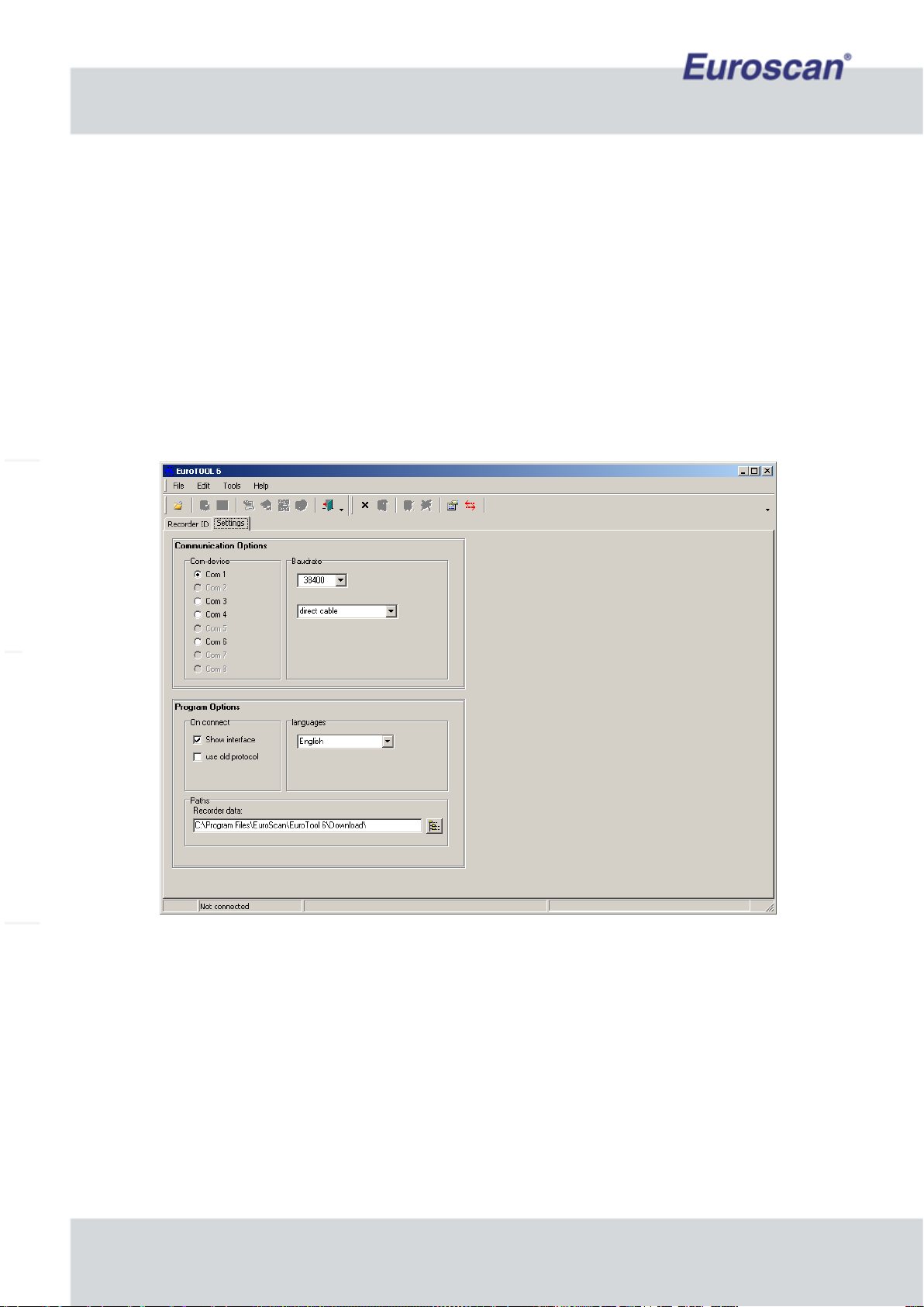
2.7 EuroTOOL Setup
The parameter settings for the MX1 recorder can be changed in two ways: by means of EuroTOOL, or
online via the EuroWEB II parameter menu. Both methods are basically the same. However, be aware that on-
line modifications make use of an iGPRS connection, which is much slower than a direct serial data connection to
a PC (9600 vs. 38400 Baud).
Also, when changing communication settings over the internet, be aware that if the wrong settings are entered,
connection might be lost when the recorder has been rebooted.
This first step is to check the connections of the recorder: there must be a serial connection between the recorder
and your pc (see chapter 2.6) and the recorder should be connected to a 10-36V power supply (see figure 3). A
green led-light on the main PCB of the MX1 will blinking.
Now you have to run EuroTOOL. Press “Edit -> Settings” to see a screen like figure 5. Select the correct COM-
port, a ‘direct cable’ connection and a Baudrate of 38400 bps.
Fig. 5 EuroTOOL Communication settings
Press “Edit -> Settings” again to go back to the main screen of EuroTOOL. Click now on “Autodetect recorder” to
find the connected MX1 device. If everything is correct, the recorder type, name and serial will appear.
Now fill the recorder’s PIN in the yellow field of the main screen. The default PIN is ‘1111’. See figure 6 on the
next page.

Euroscan MX1 9
Document number: EN-301-1:UD - based on Firmware version 1.033 and forward
Fig. 6 EuroTOOL main screen
Press ‘Edit -> Modify parameter’ to get in the recorder configuration-menu.
Check one (or more) parameter(s) and click on ‘Load’ on the right side of the screen. The MX1 sends his
parameters to the pc and if everything is correct, the selected fields become green. See the screen below.
Fig. 7 The configuration-menu of the recorder in EuroTOOL
The values of the parameters can be changed by checking a parameter, fill in a value and press ‘Write’ to send
the new value to the MX1. When data transfer is ready, the field will be green. Reading or writing all parameters
will take some time. Have a look at the manual of EuroTOOL to get more detailed information about EuroTOOL.
It’s preferable to configure the parameters before the recorder will mount to the truck! The configuration of
the iGPRS and Bluetooth settings is depicted in chapter 2.8.
All available parameters are described in Appendix C.

Euroscan MX1 10
Document number: EN-301-1:UD - based on Firmware version 1.033 and forward
2.8 iGPRS & Bluetooth setup by using EuroTOOL
iGPRS and Bluetooth technology in combination with your Euroscan MX1 recorder will reduce time needed to
extract data from your vehicles and provide a quick analysis of transport data. This chapter describes the settings
of the Bluetooth and iGPRS parameters by using EuroTOOL.
Before starting the following information is needed:
iGPRS (when installed on the recorder):
Information from your SIM card provider:
APN Server: Access Point Name, address from the server of the SIM provider.
APN User name
APN Password
DNS: Domain Name Server. It’s the internet address translator that translates a word IP into address.
For example www.google.nl = 66.249.93.147
Information from Euroscan or the end user:
When known, Customer ID. IF not, then the following information.
TCP: Transmission Control Protocol, server address of our web solution or server address of the end user
(EuroLOG)
TCP port: Channel number to get on the TCP server
Bluetooth (when installed on the recorder):
Information from the end user:
IP-address(es) of the Local Access Point(s).
PIN-code of the Local Access Point(s)
Fill in the form in appendix E to have all these important information in your vicinity.
Make sure the recorder is connected to your pc and the recorder is powered by a 10-36V DC source. See
chapter 2.5 and 2.6.

Euroscan MX1 11
Document number: EN-301-1:UD - based on Firmware version 1.033 and forward
2.8.1 iGPRS manual settings by using ‘EuroTOOL’
Example
•Start the program ‘EuroTOOL’ on your pc and ensure the recorder is correctly connected with the pc.
•Fill in the menu “parameter settings” the pin code 1111 (is default) and press ‘Autodetect recorder’.
•Go to ‘TMS parameter settings’ (SHIFT + F12) -> menu ‘Communication’.
•Communication COM4: Edit and change settings to ‘iGPRS+GPS Protocol’.
•Press ‘iGPRS’ in the same screen. The iGPRS-parameters are now displayed on the screen.
•Edit PIN code, fill in the PIN code of the SIM-card (when used).
•Edit APN server, fill in (request APN server, user name and password, details at the GSM SIM provider).
If the provider does not have APN settings leave open and accept.
•Edit DNS settings (request DNS server details at the GSM SIM provider).
If the provider does not have DNS settings leave open and accept.
•Edit TCP settings (example: www.google.nl), fill in and accept.
•Edit TCP port (example: 49201).
•Edit GPS log interval, the time is in minutes.
•Edit the GPS logging distance (when needed). This is the amount of distance which would be travelled
before data will be log again.
•Make sure all parameters what have to be edit are checked. Press on the right of the screen on ‘Write’ and
wait till the fields of the edited parameters are green.
•Exit EuroTOOL.
•
Fig. 8 Example of iGPRS settings in EuroTOOL

Euroscan MX1 12
Document number: EN-301-1:UD - based on Firmware version 1.033 and forward
2.8.2 Bluetooth manual settings by using ‘EuroTOOL’
The build-in intelligent Bluetooth module has the possibility to take over the Bluetooth parameters from a
Euroscan recorder. In this paragraph is described what the Bluetooth-settings mean and how they can be
changed.
Example
•Start the program ‘EuroTOOL’ on your pc and ensure the recorder is correctly connected with the pc.
•Fill in the menu ‘parameter settings’ the pin code 1111 (is default) and press ‘Autodetect recorder’.
•Go to ‘TMS parameter settings’ (SHIFT + F12) -> menu ‘Communication’.
•Communication COM3: Edit and change settings to ‘Bluetooth Protocol’.
•Press ‘BT (COM3)’ in the same screen. The Bluetooth-parameters are now displayed on the screen.
•Edit ‘LAP1’. This is the IP-address of the access point where the recorder will connect. Fill in LAP2, LAP3
etc. when there are more access points. Up to 16 access points addresses can be saved. If the module
isn’t able to make a connection it will try the following address. When a connection is active, the module
will continuously monitor the data. If there is no dataflow for more than a minute the module will close the
connection.
•Fill in the PIN code of the LAP.
•Fill in the disconnect time; this is the interval (in minutes) between new connections of the recorder and an
access point.
•Make sure all parameters what have to be edit are checked. Press on the right of the screen on ‘Write’ and
wait till the fields of the edited parameters are green.
•Exit EuroTOOL.
Fig. 9 Example of Bluetooth settings in EuroTOOL
Euroscan MX1 13
Document number: EN-301-1:UD - based on Firmware version 1.033 and forward
2.8.3 PDA connection
The module has also the ability to connect with a PDA. To use this feature a PDA first has to make a pairing to
the module. The module will recognize this pairing and store it in its memory. From now every minute the module
tries to connect to the paired PDA. It is possible you are not able to make a connection to the Bluetooth module.
The module will handle a LAP connection at that moment. It is not possible to make an incoming connection if the
module has made an outgoing one. This is a limitation of the Bluetooth chip.
Making a connecting goes as following:
•Open the Bluetooth manager of your PDA.
•Explore for a new device.
•Pair the device and enter the correct pin code.
•An outgoing connection will be made if the correct pin code is entered. Close this connection.
The Bluetooth module will automatically connect to your PDA from now. You can start for example the
EuroSTATE program and connect. If the connection is available the screen will be updated.
Only one connection at the time can communicate with the recorder. A LAP connection has a higher priority than
a PDA. So if the module is handling a LAP connection the PDA won’t be able to update its temperature values.
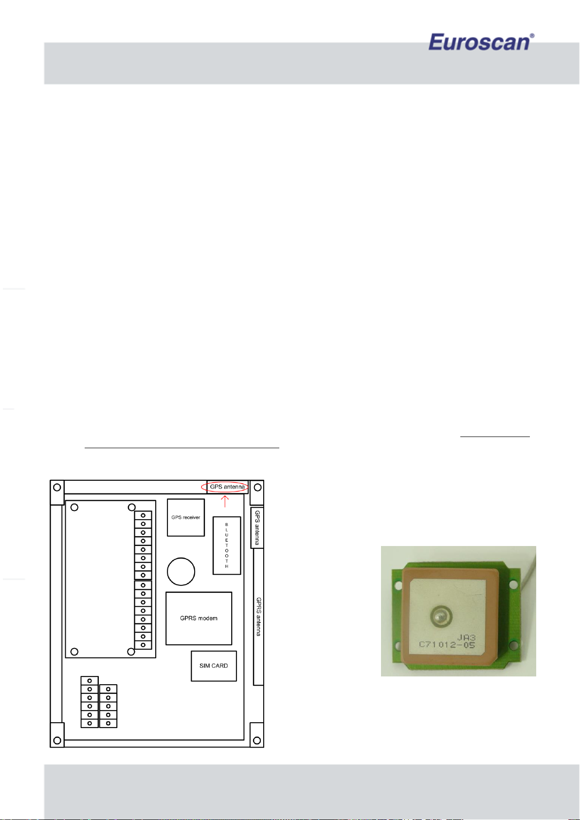
2.9 GPS-Antenna placement in MX1 recorder
In a Euroscan MX1 recorder could be up to three antennas. One for Bluetooth-, one for GPS- and one for iGPRS-
signals. All these signals are high-frequency. For good working, some setup conditions are needed.
•Always mount the MX1 recorder as high as possible, but never mount it on the roof of a truck or trailer!
•A good mounting location has as less as possible metal elements in the neighborhood. Too many metal
objects can cause bad wireless performance!
•Make sure the GPS antenna is mounted horizontal, so use the correct antenna-module holder in the box.
When the MX1 recorder is mounted vertical, place the GPS
antenna in the red marked area. See the picture on the left.
Fig. 11 The GPS antenna
Fig. 10 Location of GPS-antenna with vertical
recorder mounting

Euroscan MX1 14
Document number: EN-301-1:UD - based on Firmware version 1.033 and forward
When the MX1 recorder
is mounted horizontal,
place the GPS antenna in
the blue marked area.
See the picture on the
left. This is another area
than when the MX1
recorder is mounted
vertical!
Fig. 12 Location of GPS-antenna with horizontal recorder mounting
3. Final testing installation
The following features must be checked after installation:
Power supply
The supply voltage range is between 10-36 volts DC. The supply cable must be protected with a 10A floating
fuse at the point of connecting to V+.
Temperature sensors
After approximately 5 minutes, the temperature should be correctly displayed.
A value of -40°C indicates the possibility of a non connected sensor or a cable failure, while a value of +50°C
indicates a possible short circuit between the connector pins.
Environmental
In the case of the MX1 recorder being discarded, potential environmental hazardous
components should be removed and discarded safely.
A 3,2 V backup battery has been integrated in the recorder circuit, to preserve clock
settings etc. Separate the lithium cell from the recorder’s main PCB and deliver it to the
appropriate waste treatment centre.
Dispose separately: Do NOT throw batteries into the regular waste bin!

Euroscan MX1 15
Document number: EN-301-1:UD - based on Firmware version 1.033 and forward
3.1 Functionality check –onboard status LEDs
After the physical installation of the MX1 recorder has been established, the functionalities of the MX1 should be
inspected. Two on-board led’s (a green one and a red one) inform you about the status of the recorder. The table
below shows the meaning of both LEDs.
General
information
Power mode
Battery mode
GREEN
RED
Fridge
connection
(if installed)
Remote sensor
(if installed)
iGPRS
(if installed)
Initializing
after power on
OFF
Blinking
fast
System OK
Vehicle/fridge
battery in use
NOT charging /
NO battery
installed
Blinking
slow
System OK
Vehicle/fridge
generator in
use
NO battery
installed
Blinking
fast
System OK
Vehicle/fridge
generator in
use
Charging
ON
Blinking
fast
OFFline
(no connection
with server)
Blinking
slow
NO fridge
connection
NO remote
sensor
connection
ONline
(connection with
server)
OFF
Fridge
connection
OK
Remote sensor
OK
ONline
(connection with
server)
Backup
power in use /
power failure
NOT charging /
NO battery
installed
OFF
OFF
Failure during
initialization
ON
Table 1 LED’s status information
If only one of the two LED colours is mentioned in the table, it means that the other colour is not significant for the
status.

Euroscan MX1 16
Document number: EN-301-1:UD - based on Firmware version 1.033 and forward
3.2 Functionality check –pc menu
Parameters such as supply voltage/currents, temperature inputs, digital inputs, parameter settings, COM port
settings, communication settings and vehicle information can be displayed on your PC by means of a serial
connection and a terminal program. This terminal program will display the “MX1 menu”, which is – so to speak –
the ‘display’ of the Euroscan MX1 recorder.
Open HyperTerminal, or any terminal program on your PC, and make sure that your COM port settings are as
depicted in Fig. 5.
(COM4 may be any COM port on your pc).
Fig. 13 Configuring HyperTerminal
When HyperTerminal has been configured, the MX1 is ready to be switched on.
Make sure that the MX1 is powered by the vehicle or fridge battery, and that the 10 amp fuse is integrated into
the circuit. (See wiring diagram on page 6.)
When powered, the MX1 first initializes the communication device(s). When this is done, the recorder is ready for
use (view Fig. 6).
Type ‘h’ to display the help menu (view Fig. 7).
The menu will show the various commands that can be entered. Just press the letter which is displayed for the
command you would run. The most important things to check are if the correct hardware is found and if the
hardware settings are proper. Also check the actual temperatures/digitals (press ‘a’ and ‘d’) and the internal
voltage (press ‘v’).

Euroscan MX1 17
Document number: EN-301-1:UD - based on Firmware version 1.033 and forward
Fig. 14 Initialization
Fig. 15 Help menu

Euroscan MX1 18
Document number: EN-301-1:UD - based on Firmware version 1.033 and forward
APPENDIX A TECHNICAL DATA
Operating voltage
10 - 36 V, protected against alternator load shedding
Power consumption
(with iGPRS / GPS)
0,15 W (nominal), 2 W (maximum)
0,8 W (nominal), 12 W (maximum)
Temperature
-30°C / +70°C (in operation), -40°C / +85°C (maximum)
Humidity
97% relative humidity at 25°C
Memory size
512kB, minimum 1 year with 2 sensors and logging interval 15 min.
Inputs
6x temperature for Euroscan sensors: measuring range –40°C to
+50°C , or
6x humidity sensor, or a combination
1x digital for ignition, active > 5 V
4x digital, closed circuit, active > 5 V
Data ports
2x RS232 connectors for external devices
1x CAN connector for external device (optional)
Telematics
(optional, mounted inside MX1)
iGPRS communication, Quad band (worldwide coverage)
GPS positioning, built-in antenna (vertical / horizontal mounting slot)
Bluetooth, Class I ( >100 m communication range with ‘clear view’)
Ventilation
No special requirements. Euroscan products are designed for use in
automotive environments
IP rating
IP67
Dimensions (W x D x H)
200 x 145 x 55 millimeters
Cirquit protection
One 10 A floating fuse, fitted in the positive (+VE) power line, as
close as possible to the power connection (supplied in installation
kit)
Battery
The MX1 contains a lithium battery. This battery should be removed
before discarding and should be disposed separately.
For technical support, please contact your local supplier or Euroscan: visit www.euroscangroup.com.

Euroscan MX1 19
Document number: EN-301-1:UD - based on Firmware version 1.033 and forward
APPENDIX B FUNCTIONAL SPECIFICATION
Temperature logging
6 sensors, interval from 1..60 minutes, at -40 ºC to +50 ºC
6 sensors through external equipment (fridge
controllers/Euroscan recorders), interval from 1..60 minutes,
at -40 ºC to +50 ºC
Event logging
Digital events (on/off)
Alarm events (temperature to high/low, digital too long on/off)
Diagnostics events (power on/off/dip, firmware update, security,
error codes)
GPS events (km/miles moved, vehicle stopped/started moving,
GPS on exception (other event), speeding)
Change of temperature alarm settings (upper/lower boundaries)
Fridge set-point (change of set-point)
Fridge communication (available/not available)
GPS logging
Logging interval from 5..75 minutes
External Equipment (protocols)
Euroscan protocol: programming/downloading data, firmware
update
MX1 debug protocol: terminal protocol for installation
diagnostics
ThermoKing fridge protocol (through ThermoKing I-box): set-
points, sensors (return air), alarm doses, engine/maintenance
hours
Carrier fridge protocol: set-points, alarm codes,
engine/maintenance hours
Mitsubishi fridge protocol: set-points, alarm codes,
engine/maintenance hours
TranScan protocol: temperatures/digitals (remote sensor
module)
Old Euroscan protocol: current temperatures/digitals
Power mode / Communication mode
Power safe mode: iGPRS / GPS / Bluetooth can be switched on/off
based upon parameters or available power.

Euroscan MX1 20
Document number: EN-301-1:UD - based on Firmware version 1.033 and forward
APPENDIX C EXPLANATION OF MENUSETTINGS IN EuroTOOL
1.1
Buzzer ontime
Length of time which the buzzer is active. The value may vary
from ‘1’ until ‘10’. A higher value increases the buzz-time.
1.2
Buzzer frequency
Frequency of the buzzer. The value may vary from ‘16’ until ‘23’. A higher
value increases the buzz-frequency.
1.3
Buzzer Volume
Volume of the buzzer. The value may vary from ‘1’ until ‘127’. A higher value
increases the buzz-volume.
1.4
Automatic daylight saving
time correction
Turns the automatic summer/winter time correction on or off.
2.1
Sensor ON/OFF
Turns a sensor on or off. Data of a sensor which is off wouldn’t be saved.
2.2
Sensor name
The name of the sensor. It’s recommended to choose a clear name.
2.3
Sensor type
Select ‘Relative Humidity input’ (0..1V) or ‘Current sensor input’ (4..20 mA).
3.1
Digital input ON/OFF
Turns a digital input on or off. Data of an disabled input wouldn’t be saved.
3.2
Digital input name
The name of the digital input.
3.3
Digital input active level
Input polarity switch. Switch function if “high”: contact closed = input active. If
“low”: contact open = input active.
(Applicable for e.g. door contacts, active = open.)
3.4
Digital input alarm
On in order to activate the alarm of this digital input.
3.5
Digital input alarm delay
time
This is the time (in minutes) that a digital input has to be (and stay) active
before the alarm appears.
4.1
Compartment ON/OFF
Activates or deactivates a compartment.
4.2
Compartment name
The name of the compartment.
4.3
Input data saving ON/OFF
Turn the sensors/digital inputs in a compartment on or off.
4.4
Input alarm ON/OFF
Each input alarm can separate be enabled or disabled in a compartment.
5.1
Alarm ON/OFF
Turns a temperature-alarm on or off. (When the temperature exceeds a
limit). There are four different settable alarms available.
5.2
Alarm name
The name of an alarm. It’s recommended to choose a clear name.
5.3
Upper temp. limit
The upper temperature limit which enables the alarm.
5.4
Lower temp. limit
The lower temperature limit which enables the alarm.
5.5
Alarm delay time
The time in minutes the temperature must exceed the limit before
temperature-alarm activation. A very short exceed of the temperature limits
doesn’t direct enable the alarm.
6.1
Measurement interval
The interval (in minutes) between data saving of the measurements.
6.2
Vehicle name
It is necessary to enter an identification like registration number or chassis
number in the case of a trailer.
6.3
Company name
The name of the company.
6.4
PIN Code
The PINcode of the MX1 recorder. Default: ‘1111’.
6.5
Temperature unit
Display temperatures in degrees Celsius or Fahrenheit.
6.6
Date/time format
Choose between the European and the American date/time notation
7.1
COM protocol
The MX1 has 4 COM-ports. COM1 and COM2 are available for external
connections (e.g. with a pc). COM3 is the internal Bluetooth-port and COM4
is the internal GPS/iGPRS port.
7.2
GPS settings
The log interval of GPS data (per 5 minutes).
7.3
iGPRS settings
All iGPRS settings. See paragraph 2.8.1 in this manual for more information.
7.4
Bluetooth settings
All Bluetooth settings. See paragraph 2.8.2 in this manual for more
information.
7.5
Fridge settings
Mitsubishi fridge settings.
Table of contents


