Eurospec Push Bar Panic Bolt User manual

1Modular Push Bar Panic Bolt with Vertical Rods Rev.7
Installation Instructions
Modular Push Bar Panic Bolt with Vertical Rods to EN1125
IMPORTANT INFORMATION
PLEASE READ THESE INSTRUCTIONS CAREFULLY
This product is non handed and can be fitted on both left handed and right handed doors.
For internal use only.
Door – Maximum specification of door on which this product should be fitted.
•Maximum weight of door = 200kg
• Maximum height of door = 2500mm
• Maximum width of door = 1300mm (1170mm Bar) – 1100mm (730mm Bar)
This product is designed for peoples safety and complies with EN 1125. Do not modify
the product in anyway other than those outlined in these instructions.
2Modular Push Bar Panic Bolt with Vertical Rods Rev.7
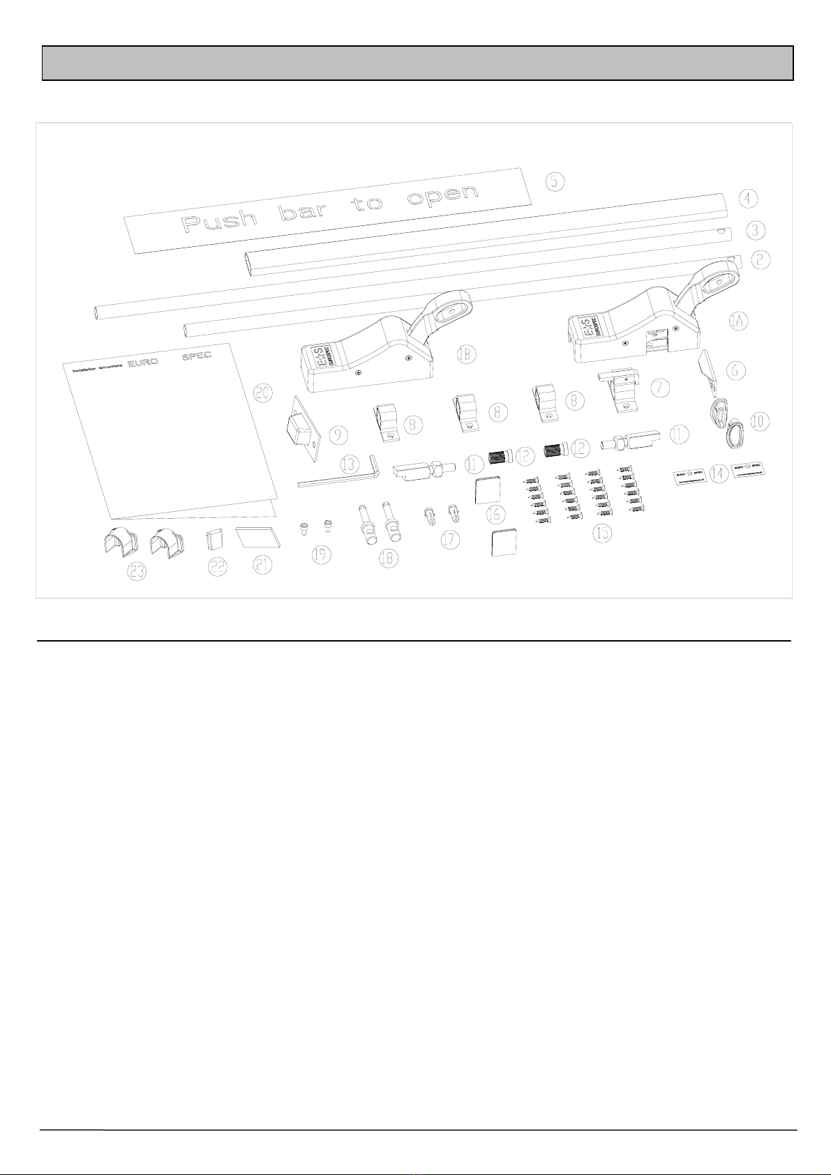
Components 1
Upon unpacking your product you will find the following parts.
(1A) Panic Bolt Box X 1
(1B) End Box X 1
(2) Short Tubular Bottom Rod X 1
(3) Long Tubular Top Rod X 1
(4) Push Bar X 1
(5) Push Bar to Open sign X 1
(6) Top Keep X 1
(7) Top Tripper Guide X 1
(8) Plain Guides X 3
(9) Bottom Keep X 1
(10) Plastic End Caps X 2
(11) Shoot Bolts X 2
PARTS LIST
(12) Knurled Plugs X 2
(13) Allen Key X 1
(14) ES Logo Labels X 2
(15) Screws (for guides, keeps and panic
bolt boxes) X 24
(16) Panic Bolt Box Blanking Covers X 2
(17) Plastic Plugs X 2
(18) Rod Connectors X 2
(19) Socket Headed Cap Screws X 2
(20) Fitting Instruction X 1
(21) 3mm Packer X 1
(22) End Box Bottom Cover X 1
(23) Rod Connector Covers X 2

3Modular Push Bar Panic Bolt with Vertical Rods Rev.7
Fitting Guide
2
For single or multi-point locking see diagrams below.
Additional locking devices may be required. Refer to relevant product instructions.
Door Suitability
This Push Bar Panic Latch and any Locking Devices can be fitted on
most wood, steel or aluminium Doors
Door size limitations
Maximum clear opening height = 2450mm.
Minimum clear opening width = 400mm per door.
Single Door Rebated Double Door Non Rebated Double Door
Door shown
with Modular
Push Bar
Panic Latch
Preparation 3
1) Check that the door and frame are in good condition and that the door operates correctly.
2) At a height of 1150 +/- 100mm, obtain the most suitable position for installation depending on
door and frame conditions (This height will be centre line mark for unit follower)

4Modular Push Bar Panic Bolt with Vertical Rods Rev.7
Installation 4
1) Remove 8 cover fixing screws from
main cases (Items 1A and 1B) (See
Fig 4.1)
2) Offer Panic Bolt Box to door in
location obtained at preparation
remembering centre line mark is
follower height
Note: Distance from door frame
edge to Panic Bolt Box must be
Min 10mm
3) Mark 6 fixing holes from obtained position. Fig 4.1
Fig 4.2
5) Measure distances (‘A’ & ‘B’) from the Panic Latch Box (1A).
See Fig 4.2
‘A’ Top of Panic Bolt Box (1A), to underside of door jamb
‘B’ Bottom of Panic Bolt Box (1A), to the final floor level
Fig 4.3
6) Cut tubular rods (Items 2 & 3) to the lengths
measured less 88mm for both. See Fig 4.3
Note: Both rods have pre-drilled holes for
fitting to the Rod connectors (Items 18)
therefore ensure the bars are cut at the
opposite end.
Remove any burrs and insert Knurled plugs
(Items 12) fully into cut ends of rods taking
care to use a wooden block to support the
opposite end when knocking the plugs into
position. See Fig 4.3
Note: If fitting External Locking attachment, rotate
follower to suit hand of door.
Right Hand door, rotate follower fully “clockwise”.
Left Hand door, rotate follower fully “anti-clockwise”.
The External Locking Attachment now needs installing according
to it’s supplied instructions.
4) Secure Panic Bolt Box (1A) to door using 6 screws (Item 15)

5Modular Push Bar Panic Bolt with Vertical Rods Rev.7
Installation – (continued)
4
7) Fit rod connectors to rods using 2 socket
headed cap screws (Items 28). Secure with
supplied Allen key (Item 13) See Fig 4.4
8) Remove Panic Bolt box from door and
insert rod connectors onto angled plates inside
main body See Fig 4.5
Note: The Push bar lever must be
depressed to enable fitting of connectors
Fig 4.4
Fig 4.5
9) Slip over one plain guide (Item 8) onto the top rod
(Item 3) then screw the shoot bolt (Item 11) fully
into the knurled plug (Item 12)
Slip the two remaining plain guides (Items 8)
over the bottom rod (Item 2) then screw the
remaining shoot bolt (Item 6) into the other
knurled plug (Item 12). Ensure both shoot bolts
are fully screwed into the knurled plugs. Do not over
tighten.
Refit the assembled Panic Bolt with rods to the door
and fix two plain guides (Items 8) to door at a central
position on both rods using screws (Items 23) ensuring
vertical alignment with door edge. The other plain guide
does not require fixing at this stage. See Fig 4.6
Fig 4.6

6Modular Push Bar Panic Bolt with Vertical Rods Rev.7
Installation – (continued)
4
10) With the door in the closed position. Fully depress
the Push bar lever and holding the door in a closed
position, adjust the top shoot bolt (Item 11) until a
3-4mm required clearance is achieved from the
underside of frame to top of shoot bolt. The bevel of shoot
bolt must be facing the door (adjust if necessary)
See Figs 4.7 & 4.8
With the door open, slide the top tripper guide (Item 7)
over the top shoot bolt and close the door. Fully depress
the push bar lever, inset 3mm packer to hold the top
shoot bolt. This now gives the position of the top guide.
Mark through and secure into position. Fig 4.7
Fig 4.8
Bevelled edge
2-3mm
11) With the rods held into position by the top tripper,
adjust the bottom shoot bolt to obtain a required
clearance of 2-3mm. See Fig 4.9
Note: Ensure bevelled edge of shoot bolt is facing the door
Slide the remaining plain guide down into position
maintaining a gap of 19mm between the underside of the
guide and threshold. Mark through and secure into
position See Fig 4.7
Fig 4.9
2-3mm
Bevelled edge

7Modular Push Bar Panic Bolt with Vertical Rods Rev.7
Installation – (continued)
4
12) Mortise out for Top and Bottom keeps as shown,
including the clearance depth (approximately 12mm)
for the top shoot bolt when the door is in the closed
position. Adjust keeps as required ensuring that the
shoot bolts are not a loose or tight fit into the keeps.
See Figs 4.10 & 4.11
When the keeps are screwed into position, open and
close the door to ensure the top tripper releases
against the top keep and the bottom rod engages
fully into the bottom keep. Also check the tripper
catch holds the bars open when the door opens.
Top Keep Fig 4.10
Fig 4.11
Bottom Keep
13) Screw End Box on the hinge side of the door
at the distance shown in Fig 4.12, ensuring
the box is vertically aligned and in line
horizontally with the Panic Bolt Box. If the
door is too narrow, remember to leave a 10mm
gap between end box and door frame. Mark
through and secure into position.
14) Place End Box blanking cover (item 22) onto
bottom of metal base, depress arm and fit End
Box cover. Secure with screws.
Insert Panic Bolt Box blanking covers (item 16)
into Panic Bolt Box Cover, depress arm and fit
Latch Box to metal base at the same time
inserting rod connector covers (item 23).
Secure with screws. See Fig 4.13
Note: If the distance in Fig 4.12 is less than
674mm, remove this difference from the bar
15) Insert the Push Bar through the Panic Bolt
lever arms and insert plastic caps at each end
ensuring they are fully pressed into position.
Use the Allen key to secure the Push Bar into
position ensuring the bar is tightly secured.
See Fig 4.13
16) Check the operation of the Bar and rods are
satisfactory.
17) Apply self adhesive ‘Push Bar to Open’ Sign
to door and stick the optional ES logo labels
into the recesses of the Panic Bolt boxes .
Fig 4.12
Fig 4.13
12mm

8Modular Push Bar Panic Bolt with Vertical Rods Rev.7
Operational Instructions
5
Operational Instructions and Maintenance
6
Ensure that the Keeps are secure, clean and free from any obstruction, check that Push Bar Panic
Bolt operates correctly, and periodically apply grease to top and bottom shoot bolts.
PLEASE LEAVE THESE INSTRUCTIONS WITH THE END USER
Stancliffe Street
Mill Hill
Blackburn
BB2 2QR
Tel: +44 (0) 1254 274100
Fax: +44 (0) 1254 274111
Web: www.eurospec.co.uk
This Push Bar Panic Bolt is fitted to comply with EN1125. No instruction of operation is required. For
the end user, the Push Bar Panic Bolt should be easily operated by hand or body pressure in a
panic situation.
Table of contents
Popular Door Lock manuals by other brands

LockState
LockState RemoteLock openEDGE RG Hardware installation

Assa Abloy
Assa Abloy Yale Pro SL Installation and programming instructions

iSysmart
iSysmart ZigBee SGZB05A user manual

Yale
Yale real Living YRC226 Installation and programming instructions

Salto
Salto LA1T05 Series installation guide

Maco
Maco A-TS Assembly instructions


