Eurospec XIA5002SV User manual

1Push Pad Rev.7
Installation Instructions
Push Pad Emergency Exit Device EN179
PLEASE READ THESE INSTRUCTIONS CAREFULLY
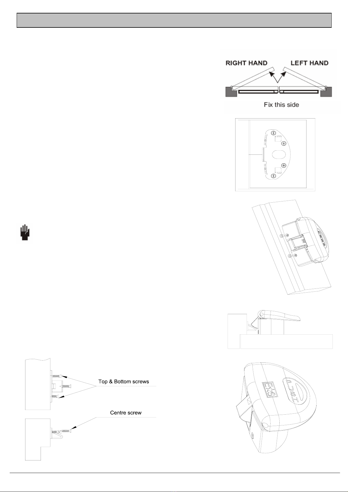
This product is non handed and can be fitted on both left and right handed single doors
For internal use only.
This product is designed for peoples safety and complies with EN179. DO NOT modify the product in
anyway other than those outlined in these instructions.
IMPORTANT INFORMATION
Door – Maximum specification of door on which this product should be fitted.
•Maximum weight of door = 200kg
• Maximum width of door = 1300mm

2Push Pad Rev.7
Diagram 1 Diagram 2
Diagram 3
1. At a height of 1000mm +/- 100mm, mark the door at a measurement of 55mm from the edge of
the door frame. This distance is the centre line of the spindle hole. See Diagrams 1 & 3.
2. Detach Mounting Plate from Push Pad unit by using allen key provided to remove the two screws.
See diagram 2.
Slide mounting plate to disconnect from main body
3. Drill four small pilot holes for mounting plate and one further 25mm diameter hole for follower.
The 25mm hole needs to be 15mm deep to accept the follower.
Refer to Diagram 3 for the position and dimensions of holes. All dimensions are in mm.
Note: Diagram 3 is not a template.
If fitting an External Locking Attachment, drill a 3mm diameter spindle hole through the door.
This will be centre line point for installing External Locking Attachment.
The External Locking Attachment requires to be fitted using it’s relevant fitting instructions
at this stage and the 25mm spindle hole for the Push Pad needs to be drilled through the
door.
Installation
3Push Pad Rev.7
.
4. Identify correct door handing, See Diagram 4 and
prepare spindle rotation as follows:
Right Hand door, rotate follower fully “clockwise”.
Left Hand door, rotate follower fully “anti-clockwise”.
Note: If External Locking Attachment is not required, please proceed to step 5.
Diagram 5
Diagram 6
Diagram 7
Diagram 8 Diagram 9
8. Open the door and fit the top and bottom screws see
Diagram 8, then close door to ensure Striker is correctly
positioned.
Adjust if necessary and fit the centre screw to the
middle of the striker. See Diagram 8
Diagram 4
5. Securely screw Mounting Plate to door using the four pre-
drilled pilot holes. See Diagram 5.
6. Refit Push Pad on the Mounting Plate and secure with
two screws removed earlier. See Diagram 6.
7. With door in closed position, hold Striker on the door frame
and move it until it touches the latch bolt. See Diagram 7.
Mark frame for relevant fixing holes.
Note: The straight edge of the striker plate faces the door
9. Stick the LH or RH Photo Luminescent PUSH sign in the
recess of Push Pad. See Diagram 9.
Installation – (Continued)

4Push Pad Rev.7
PLEASE LEAVE THESE INSTRUCTIONS WITH THE END USER
Stancliffe Street
Mill Hill
Blackburn
BB2 2QR
Tel: +44 (0) 1254 274100
Fax: +44 (0) 1254 274111
www.eurospec.co.uk
Ensure all fixing screws are secure and that the striker is clean and free from obstruction. Check
Push Pad operates correctly.
This Push Pad is fitted to comply with EN179. No instruction of operation is required.
Once Installation is completed, check Push Pad for correct operation.
To test this, apply pressure to the door and release it using Push Pad.
Final Checks
Operational Instructions
Maintenance
Table of contents
Other Eurospec Door Opening System manuals

Popular Door Opening System manuals by other brands


Besam
Besam Swingmaster MP Installation, adjustment and maintenance instructions

Assa Abloy
Assa Abloy SARGENT 1431 Series instructions

GAL
GAL MOVFR Quick setup

Häfele
Häfele Finetta T 70 VF manual

AGS
AGS D-PL Instructions for fitting, operating and maintenance

Stanley
Stanley MA900ñ Installation and owner's manual

WITTUR
WITTUR Hydra Plus UD300 Instruction handbook

Alutech
Alutech TR-3019-230E-ICU Assembly and operation manual

Pamex
Pamex KT-INP35 Installation instruction

MPC
MPC ATD ACTUATOR 50 ATD-313186 Operating and OPERATING AND INSTALLATION Manual

Chamberlain
Chamberlain T user guide

Dorma
Dorma MUTO COMFORT M DORMOTION 50 Mounting instruction