Eurotech PCN-1001 User manual
PCN
-1001
Passenger & People Counter
USER MANUAL
Rev
4.0 – 23 December 2011 – PCN-1001_UserMan_En_4.0

© 2011 Eurotech
Trademarks
All trademarks both marked and unmarked appearing in this document are the property of their respective
owners.
Revision history
REVISION
DESCRIPTION
DATE
2.0
•Joined together the programming and the Installation
manuals into “PCN-1001_Manual_2.0”
September 2007
2.1
•Corrected M1 & M2 pinouts
November 2007
2.2
•
Minor changes
November 2007
2.3
•Added “The maximum suggested number of Counters to
connect together is 5” on note on page 19
•
Added cable kit note on pages 20 and 21
February 2008
2.4
•Added Notes on page 49
•Removed “testin0/1” command from “The RS485 protocol”
table on pag76
April 2008
2.5 •Relevant changes applied to pages: 15, 36, 40, 46 to 48,
53 to 55
August 2008
2.6
•Manual layout update
•“Installing/Updating the software” paragraph updated
•WinClient screenshots updated to rev 2.3.3
May 2009
2.7 •Updated CRC16 Algorithm on page 80
•Updated RS485 information on page 67 and 68
February 2010
2.8
•
Small corrections on pages 11 and 68
March 2010
2.9
•
Updated WinClient features to reflect version 2.3.5
May 2010
3.0 •General contents review
•
Updated WinClient features to reflect version 2.3.6
June 2010
3.1
•Added paragraph Cleaning on page 7
•Updated paragraph The “Wide-Gate” tab on page 63
•Updated paragraph Notes about the Digital I/O interface
on page 61
September 2010
3.2
•Minor changes
April 2011
4.0 •
General contents review
23 December 2011

Table of contents PCN-1001 User manual
3
PCN
-1001_UserMan_En_4.0
Table of contents
Trademarks.................................................................................................................................................................. 2
Revision history ........................................................................................................................................................... 2
Table of contents .......................................................................................................................................................... 3
Important user information .......................................................................................................................................... 7
Alerts that can be found throughout this manual......................................................................................................... 7
Safety notices and warnings........................................................................................................................................ 8
Do not operate in an explosive atmosphere .......................................................................................................... 8
Antistatic precautions ............................................................................................................................................. 8
Connection to power supply or other devices ........................................................................................................ 8
Installation .............................................................................................................................................................. 9
Ventilation............................................................................................................................................................... 9
Maintenance........................................................................................................................................................... 9
Cleaning ................................................................................................................................................................. 9
Life support policy...................................................................................................................................................... 10
Warranty .................................................................................................................................................................... 10
CE Notice................................................................................................................................................................... 10
WEEE ........................................................................................................................................................................ 10
RoHS ......................................................................................................................................................................... 10
Technical assistance ................................................................................................................................................. 11
Transportation ...................................................................................................................................................... 11
Device labelling .................................................................................................................................................... 11
Conventions and definitions used within this Manual................................................................................................ 12
The “Mode” of the register:................................................................................................................................... 12
Hexadecimal numbering: ..................................................................................................................................... 12
Control Unit, Host PC........................................................................................................................................... 12
PCN-1001, Device, Counter, Master, Slave ........................................................................................................ 12
PART 1–INTRODUCTION ................................................................................................................................................. 13
Contents of the box .................................................................................................................................................... 15
PCN-1001 general description ................................................................................................................................... 16
Front interfaces. The service panel ........................................................................................................................... 18
LED indicator assignment .................................................................................................................................... 18
Notes about the Mini USB port ............................................................................................................................ 18
Rear interfaces .......................................................................................................................................................... 19
Power Supply Specifications ..................................................................................................................................... 20
Mechanical Characteristics........................................................................................................................................ 20
PART 2–PCN-1001 INSTALLATION PROCEDURE ............................................................................................................. 21
Step 1: Find the best mounting location................................................................................................................... 23
The PCN-1001 field of view and the Detection area ................................................................................................. 24
The PCN’s field of view ........................................................................................................................................ 24
The Detection area............................................................................................................................................... 25
Number of PCN-1001 devices required .................................................................................................................... 27
Example ............................................................................................................................................................... 27
How to connect one PCN-1001 ........................................................................................................................... 28
How to connect two PCN-1001 devices in Wide-gate configuration ................................................................... 29

Table of contents PCN-1001 User manual
4
PCN-
1001_UserMan_En_4.0
How to connect three or more PCN-1001 devices in Wide-gate configuration ................................................... 30
Note about PCN-1001 devices connected in Wide-gate configuration................................................................ 31
Step 2: Install a PCN-1001 .......................................................................................................................................... 33
Step 2.1: Connect the rear side interfaces and adjust the angle of the front panel .................................................. 33
1: Loosen the front panel to simplify the cabling procedure: ............................................................................... 33
2: Connect all the interfaces and prepare the power connections to M1............................................................. 33
3: Adjust the angle of the front panel and secure the front panel ........................................................................ 34
Note about installing 2 or more PCN-1001 in Wide-gate configuration..................................................................... 34
Step 2.2: Fix the PCN-1001 to the ceiling ................................................................................................................. 35
Step 3: Configure the network between PCN-1001 and Host PC ........................................................................... 36
Step 3.1: Turn on the PCN-1001power ..................................................................................................................... 36
Step 3.2: Connect the PCN-1001 with the Host PC .................................................................................................. 36
Step 3.3: Configure the network on the Host PC ...................................................................................................... 37
Step 3.4: Configure the TCP/IP Properties ............................................................................................................... 38
Step 3.5: Configure the Host PC firewall ................................................................................................................... 39
Step 4: Use WinClient to network PCN-1001 & Host PC ......................................................................................... 40
Step 4.1: Set the main parameters in the “Controls” tab ........................................................................................... 41
1: Set the “Date and Time settings” ..................................................................................................................... 41
2: Set the “Distance Configuration”...................................................................................................................... 41
3: Set the “Light intensity” .................................................................................................................................... 41
4: Set the “In/Out direction” .................................................................................................................................. 42
5: Set the “Door kind” ........................................................................................................................................... 42
6: Set the “Door threshold”................................................................................................................................... 42
7: Use the “Scene background” button to acquire and store the background ..................................................... 43
Step 5: Use WinClient to test the tracking of people .............................................................................................. 45
Example of counting .................................................................................................................................................. 46
How the threshold works when using digital inputs................................................................................................... 47
PART3 – THE PCN-1001 SOFTWARE.............................................................................................................................. 49
Install/update the software......................................................................................................................................... 51
The pcn-1001-Imgserver ........................................................................................................................................... 51
The pcn-1001-demo-win32........................................................................................................................................ 51
The WinClient....................................................................................................................................................... 51
The RS485_GUI................................................................................................................................................... 51
Install/update the software on the Host PC ............................................................................................................... 52
Install / Update WinClient and RS485_GUI on the PCN-1001 ............................................................................ 52
Updating Imgserver on the PCN-1001................................................................................................................. 54
Know WinClient........................................................................................................................................................... 57
The drop-down list................................................................................................................................................ 58
The Start and Stop buttons .................................................................................................................................. 58
PCN Configuration Files management (PCF)...................................................................................................... 58
The status bar ...................................................................................................................................................... 59
The tabs ............................................................................................................................................................... 60
The “Controls” tab...................................................................................................................................................... 61
The “Date and Time settings” panel..................................................................................................................... 61
The “Distance Configuration” panel ..................................................................................................................... 61
The “Light intensity” panel.................................................................................................................................... 61
The “In/Out direction” panel ................................................................................................................................. 62
The “Door kind” panel .......................................................................................................................................... 62
The “Door threshold” panel .................................................................................................................................. 62
The “Data records” panel ..................................................................................................................................... 63

Table of contents PCN-1001 User manual
5
PCN
-1001_UserMan_En_4.0
The “Scene background” button .......................................................................................................................... 65
The “Reset counters” button ................................................................................................................................ 66
The “Restore Factory Settings” button................................................................................................................. 66
The “System update” button................................................................................................................................. 66
The “I/O Settings” tab ................................................................................................................................................ 67
The “Optocoupled I/O functions” panel ................................................................................................................ 67
The “Optocoupled I/O test” panel......................................................................................................................... 68
Notes about the Digital I/O interface .................................................................................................................... 69
Note: How to simulate a digital input.................................................................................................................... 70
The “RS485 Setup” panel .................................................................................................................................... 70
The “Wide-Gate” tab .................................................................................................................................................. 71
Setting up the PCN-1001 devices for the Wide-Gate configuration .................................................................... 71
The “Advanced (1/2)” tab........................................................................................................................................... 73
“No Tracking Zone” panel .................................................................................................................................... 73
“Single Way Tracking” panel ................................................................................................................................ 75
“PCN-1001 System diagnostic” panel.................................................................................................................. 75
“Use Move detection” panel ................................................................................................................................. 76
“Time Background” panel..................................................................................................................................... 77
The “Advanced (2/2)” tab........................................................................................................................................... 78
“Stairs Upgrade” panel ......................................................................................................................................... 78
Test an RS485 connection and use the RS485_GUI................................................................................................ 79
Introduction ................................................................................................................................................................ 79
Notes about the RS485 serial bus for development purposes .................................................................................. 80
Example of RS485 network ....................................................................................................................................... 81
Configure the RS485 port of the PCN-1001.............................................................................................................. 82
Start the RS485_GUI. Configure the RS485 port of the Host PC ............................................................................. 83
“Recipient” and “Polling” panels........................................................................................................................... 84
“System Info” panel .............................................................................................................................................. 85
“IP Address” panel ............................................................................................................................................... 85
“Date and Time settings” panel ............................................................................................................................ 85
“System Update” panel ........................................................................................................................................ 85
“Optocoupled Inputs functions” panel .................................................................................................................. 86
“Optocoupled outputs open time” panel............................................................................................................... 86
“Log” panel ........................................................................................................................................................... 86
The communication protocol ..................................................................................................................................... 87
Polling................................................................................................................................................................... 88
Scenarios ............................................................................................................................................................. 88
The DATA field ..................................................................................................................................................... 89
Example 1: setting the LED intensity to 100 ........................................................................................................ 90
Example 2: requesting the kernel version installed in the PCN-1001.................................................................. 90
Commands availability ......................................................................................................................................... 91
CRC16 Algorithm....................................................................................................................................................... 95
APPENDIX .................................................................................................................................................................... 97
Note for mounting the front panel with angles from 20° up to 45° ........................................................................ 99
PCN-1001 Cable kits ................................................................................................................................................. 100
CBL-1001-00 cable kit ............................................................................................................................................. 100
7030000330L Multifunction Cable ..................................................................................................................... 100
Male USB Mini-B to Male USB Type “A” Cable ................................................................................................. 101
Male USB Type “A” to Female USB Type “A” Extension Lead.......................................................................... 101
703704001SL Adapter (Male USB Type “A” to Male DB9 for RS485 Cable).................................................... 102
CBL-1001-01 cable kit ............................................................................................................................................. 103
7010000108L Cable for direct connection ......................................................................................................... 103

Table of contents PCN-1001 User manual
6
PCN-
1001_UserMan_En_4.0
Example of direct connection using the CBL-1001-01....................................................................................... 104
CBL-1001-02 cable kit ............................................................................................................................................. 105
7030000331L Cable for Multiple Connection..................................................................................................... 105
Example of direct connection using the CBL-1001-02....................................................................................... 106
Rear interfaces .......................................................................................................................................................... 107
Power Supply Specifications ................................................................................................................................... 108
Mechanical Characteristics...................................................................................................................................... 108
PCN-1001 Logon ....................................................................................................................................................... 109
Troubleshooting........................................................................................................................................................ 111
Standards Compliance ............................................................................................................................................. 113
Cut-out template........................................................................................................................................................ 115
Notes ........................................................................................................................................................................ 117

Important user information PCN-1001 User manual
7
PCN
-1001_UserMan_En_4.0
Important user information
Please carefully read and understand the instructions in this manual before using the device.
Whenever you have any doubts regarding the operation of this device, first consult this manual, and then if you
are still unable to resolve your issue, contact the Eurotech Technical Support Team for assistance.
To lower the risk of personal injury, electric shock, fire or damage to equipment, you must observe the
following precautions, as well as using good technical judgment, whenever installing or using this
device.
Eurotech has made every effort to ensure the accuracy of this document; however, Eurotech assumes no liability
resulting from any error/omission in this document, or from the use of the information contained herein.
Eurotech reserves the right to revise this document or to make changes to its content at any time without any
obligation to notify any person of such revisions or changes.
Alerts that can be found throughout this manual
Symbol
Meaning
DANGER!
Information highlighting potential electrical shock hazards:
•Personal injury or death could occur.
•Damage to the system, connected peripheral devices, or software could occur.
Appropriate safety precautions should always be used; these should meet the requirements set out for the
environment that the equipment will be deployed in.
WARNING!
Information highlighting potential hazards:
•Personal injury or death could occur.
•Damage to the system, connected peripheral devices, or software could occur.
Appropriate safety precautions should always be used; these should meet the requirements set out for the
environment that the equipment will be deployed in.
NOTE
These will highlight important features or instructions.
Important user information PCN-1001 User manual
8
PCN-
1001_UserMan_En_4.0
Safety notices and warnings
Users must observe the following safety precautions during all phases of operation, service, and repair of the
device. Failure to comply with these precautions or with specific warnings elsewhere in this manual violates
safety standards of design, manufacture, and intended use of the device.
Eurotech assumes no liability for the customer’s failure to comply with these requirements.
The safety precautions listed below represent warnings of certain dangers of which Eurotech is aware. You, as
the user of the device, should follow these warnings and all other safety precautions necessary for the safe
operation of the device in your operating environment.
Do not operate in an explosive atmosphere
WARNING!
Do not operate the equipment in the presence of flammable gases or fumes. Operation of any
electrical equipment in such an environment constitutes a definite safety hazard.
Antistatic precautions
WARNING!
To avoid ESD (Electro Static Discharge) damage, always use appropriate antistatic precautions
when handing any electronic equipment.
Connection to power supply or other devices
DANGER!
Before applying power to the system, thoroughly review all installation, operation, and safety
instructions.
Failure to install the system power supply correctly or to follow all operating instructions correctly
may create an electrical shock hazard, which can result in personal injury or loss of life, and/or
damage to equipment or other property
•To avoid injuries, always disconnect power and discharge circuits before touching them.
•Only start the device with a power supply that meets the requirements stated on the voltage label. In
case of uncertainties about the required power supply, please contact the Eurotech Technical Support
Team or the electricity authority
•Before connecting other equipment carefully read any supplied instructions
•Always disconnect the power before connecting or disconnecting cables
•Do not perform connections with wet hands
•Check any power cords for damage before use
•Use certified power cables. The power cable must meet the requirements (voltage and current) of the
device.
•Position cables with care. Avoid positioning cables in places where they may be trampled on or
compressed by objects placed on them. Take particular care of the plug, power-point and outlet of
power cable
•Avoid overcharging any power outlets
•Only apply power to the device or connected equipment after checking that all the above conditions
have been met

Important user information PCN-1001 User manual
9
PCN
-1001_UserMan_En_4.0
Installation
WARNING!
•Verify that the mounting location can withstand the added loads caused by the addition of the
device, it should be firmly secured so that it will not cause any potentially hazardous
situations (e.g. falling down due to vibration or shock)
•
Do not operate the device near heat sources or flames.
NOTE:
If the device must be moved from one place to another with different ambient temperatures, ensure sufficient
time for the temperature of the device to stabilize before repowering.
Ventilation
WARNING!
Ensure adequate ventilation to avoid overheating, Eurotech suggests the following steps:
•When installing the device within a cabinet, rack or other enclosed space, be sure to leave
sufficient space to allow adequate air circulation
•Do not block any ventilation openings
Maintenance
DANGER!
•Never open, dismantle or repair the device!
•For your maintenance or repair requirement please contact a qualified Eurotech engineer.
If the device does not function correctly and you are unable to find a solution, feel free to contact
the Eurotech Technical Support Team.
If the equipment does not work properly, especially if smells unusual, unplug it immediately and contact Technical
Support Eurotech (see fourth cover of this manual for details).
Cleaning
WARNING!
When cleaning the device, remember to:
•Ensure sufficient ESD protection during the cleaning process
•Remove any power from the device
•Use a dry cloth to remove dust and fingerprints from the external casing
•
Do not use detergents, aerosol sprays, solvents or abrasive sponges
To clean the lenses:
1. Use a blower to remove any dust
2. Use water-based, non-flammable, glass/plastic cleaner products to remove all types of
dirt; grease, oil, nicotine etc. from the lenses
3. Gently wipe the lenses with a lint-free cloth.
WARNING!
The PCN-1001 should not be used for extended periods of time with the service plate removed.
Doing so can cause dust and other particulates to enter the system thus causing degradation to the
optics.
If it is necessary to have extended access to the Mini-USB connector, take appropriate precautions
to stop any particulates from entering.
Important user information PCN-1001 User manual
10
PCN-
1001_UserMan_En_4.0
Life support policy
WARNING!
Users must not use Eurotech products as critical components of life support devices or systems
without the express written approval of Eurotech.
Warranty
Please contact your local Eurotech Sales Office for detailed warranty terms and conditions.
Refer to the back covers of this manual for full contact details.
CE Notice
This product is marked CE.
The CE Mark on the product indicates that the system has been tested and conforms to
the provisions of the 2004/108/EC Electromagnetic Compatibility (EMC) Directive and the
2006/95/EC Low Voltage Directive (LVD).
Eurotech shall not be liable for use of our products with equipment (i.e., power supplies,
personal computers, etc.) that are not CE marked and that do not meet the PCN-1001
technical requirements indicated in this manual.
WEEE
The information below complies with the regulations set out in the 2002/96/EC directive, subsequently
superseded by 2003/108/EC. It refers electrical and electronic equipment and the waste management of such
products.
When disposing of a device, including all of its components, subassemblies and materials that are an integral part
of the product, you should consider the WEEE directive.
The use of the following symbol, attached to the equipment, packaging, instruction
literature, or the guarantee sheet, states that the device has been marketed after August
13th 2005, and implies that you must separate all of its components when possible, and
dispose of them in accordance withal waste disposal legislations:
•Because of the substances present in the equipment, improper use or disposal of the refuse can cause
damage to human health and the environment.
•With reference to WEEE, it is compulsory not to dispose of the equipment with normal urban refuse; an
arrangement for separate collection and disposal is essential.
•To avoid any possible legal implications users should contact the local waste collection body for full recycling
information.
RoHS
This device, including all the components, subassemblies and the consumable materials that are an integral part
of the product, have been manufactured in compliance with the European directive 2002/95/EC known as the
RoHS directive (Restrictions of the use of certain Hazardous Substances). This directive targets the reduction of
certain hazardous substances previously used in electrical and electronic equipment (EEE).
Important user information PCN-1001 User manual
11
PCN
-1001_UserMan_En_4.0
Technical assistance
For any technical questions, or if you cannot isolate a problem with your device, or for any enquiry about repair
and returns policies, feel free to contact your local Eurotech Technical Support Team.
See the back cover for full contact details.
Transportation
When transporting any module or system, for any reason, it should be packed using anti-static material and
placed in a sturdy box with enough packing material to adequately cushion it.
Warning:
Any product returned to Eurotech that is damaged due to inappropriate packaging will not be
covered by the warranty!
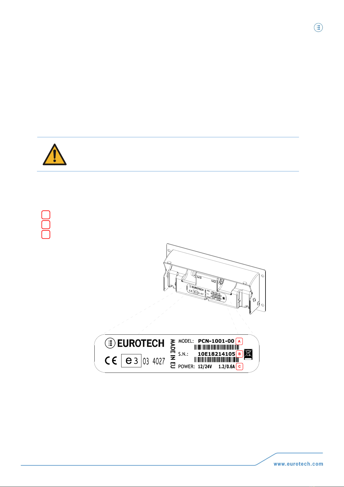
Device labelling
On the rear side of the device you can find a label displaying the following information:
Model Number
Serial Number
Power Requirements
A
B
C

Important user information PCN-1001 User manual
12
PCN-
1001_UserMan_En_4.0
Conventions and definitions used within this Manual
The following conventions and definitions are used throughout this manual:
The “Mode” of the register:
SYMBOL / TEXT
DEFINITION
RW
Readable and Writable register
RO
Read only register
W
Meaning of the register when written
R
Meaning of the register when read
Hexadecimal numbering:
Hexadecimal numbers are indicated like this: 0x01.
Control Unit, Host PC
The terms “Control Unit” and “Host PC” are used to describe a computer connected to the PCN-1001 for
maintenance and configuration activities.
PCN-1001, Device, Counter, Master, Slave
In this manual the terms:
•“PCN-1001”
•“Device”
•“Counter”
•“Master”
•“Slave”
are used to describe the PCN-1001 people/passenger counter.


(This page has been intentionally left blank)

Contents of the box PCN-1001 User manual
15
PCN
-1001_UserMan_En_4.0
Contents of the box
Two part numbers are available:
1. PCN-1001-00. This contains:
•1x PCN-1001 device
•1x PCN-1001 Extender. For further information refer to ‘To mount the front panel with angles from 20°
up to 45°’paragraph on page 34
•2x hexagonal socket screws (M3 x 6) and 2x split washers. These allow you to mount the Extender
PCN-1001 Passenger Counter
PCN-1001 Extender with screws and washers
2. DTK-1001-00. This is the PCN-1001 development kit and contains:
•1x PCN-1001-00 (as described above)
•1x CD-ROM with software, utilities and documentation
•1x CBL-1001-00 Cable Kit. For further information refer to the ‘CBL-1001-00 cable kit’ paragraph on
page 100
PCN-1001 with extender, screws and washers
CD-ROM
CBL-1001-00 Cable Kit
NOTE:
With both order codes the installer has to provide suitable fixing screws or bolts. This will depend
on the location, material, and any applicable regulation.
PCN-1001 general description PCN-1001 User manual
16
PCN-
1001_UserMan_En_4.0
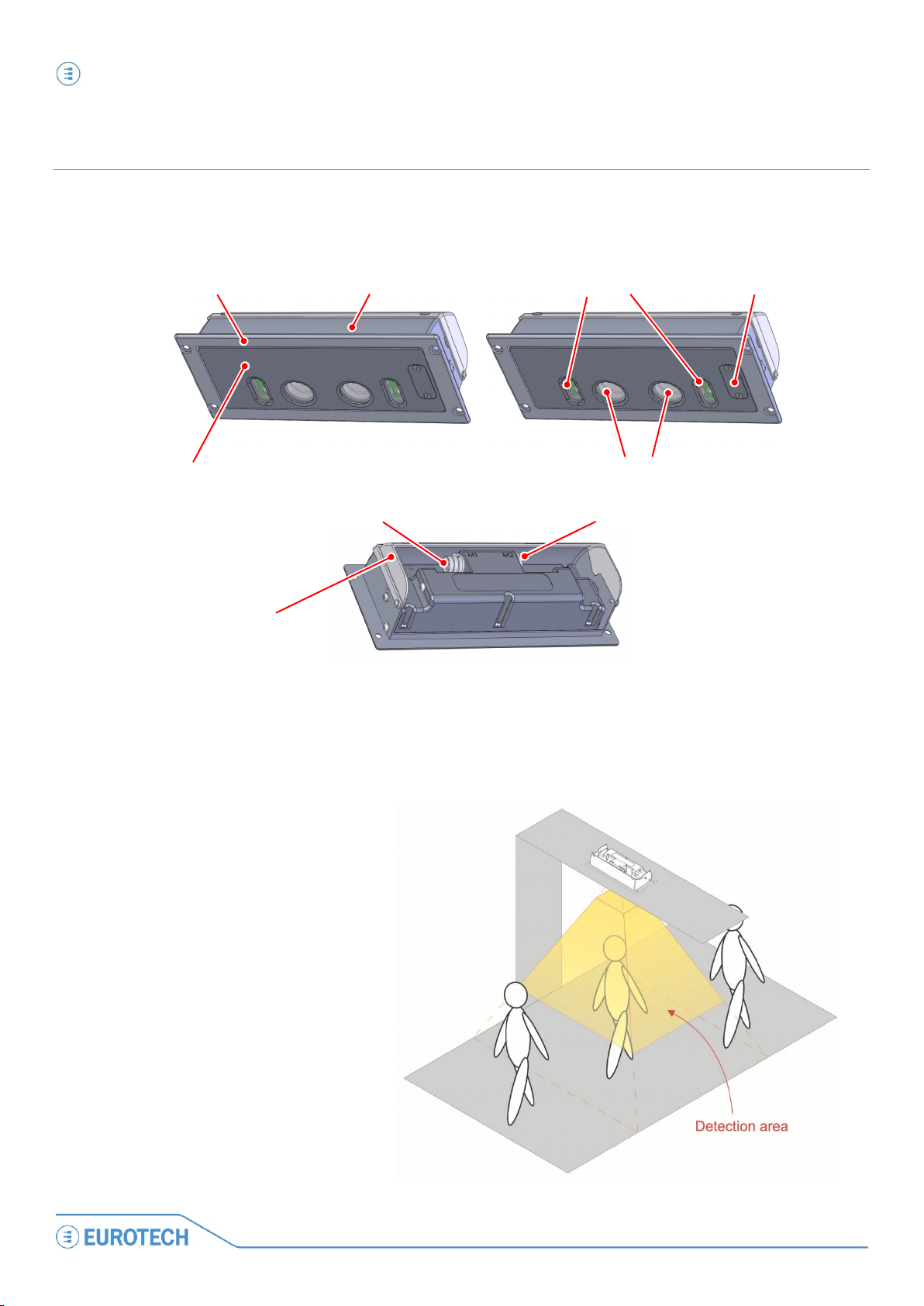
PCN-1001 general description
The PCN-1001 is a compact and autonomous device based on non-contact stereoscopic vision technology. It has
been designed to count passengers entering and exiting the doorways of buses and trains, but can also be used
to count people as they enter or leave buildings or any other area with restricted access.
Figure 1. PCN-1001 front and rear
The stereoscopic cameras capture images of the area below the device (Detection area); the built-in high
luminosity infrared LED emitters allow for reliable operations in any type of lighting condition.
The PCN-1001 analyses any objects
moving within the Detection area,
considering height, shape and direction.
After determining if an object is a person
entering or leaving, the incoming or
outgoing values are stored accordingly,
along with time and date information.
This information is immediately available
via RS485 or downloaded at a later date
for analysis.
M2
M1
Front panel with adjustable angle
Frame (with mounting holes) Enclosure
Extender
Infrared LED emitters Service panel
Stereoscopic cameras (sensors)

PCN-1001 general description PCN-1001 User manual
17
PCN
-1001_UserMan_En_4.0
The PCN-1001 has to be installed so that the front panel is placed horizontal to the floor. To achieve this, the
angle between the front panel and the enclosure can be adjusted from 0° to 20° (up to 45° using an extender: the
extender also increases the protection of the rear side). Thanks to these characteristics the PCN-1001 can be
mounted in a variety of locations, even on non-horizontal surfaces.
Many PCN-1001 systems can be installed in a vehicle, working stand-alone or networked together with a vehicle
server - the Control Unit - that can pre-process, store, and upload information from all the passenger counters.
To increase accuracy, door sensors can be used in combination with the PCN-1001.
NOTE:
For further information about PCN-1001-00 operating accuracy you can refer to Application Note An0074
(http://www.eurotech.com/DLA/AN/An0074.pdf).
Adjustable front panel
to keep the PCN-1001
horizontal

PCN-1001 general description PCN-1001 User manual
18
PCN-
1001_UserMan_En_4.0
Front interfaces. The service panel
A Service panel, located on the front of the PCN-1001, gives access to some interfaces used for configuration,
maintenance, and development of applications.
NOTE:
The service panel is held in place by 2 Torx M3 * 6 screws, these should be removed using a Torx T9
screwdriver.
WARNING!
The PCN-1001 should not be used for extended periods of time with the service plate removed.
Doing so will cause dust and other particulates to enter the system, causing degradation to the
optics. If it is necessary to have extended access to the Mini-USB connector, take appropriate
precautions to stop any particulates from entering.
LED indicator assignment
LED COLOUR
MEANING
LED STATUS
Green
Power status
ON: PCN-1001 turned ON
OFF: PCN-1001 turned OFF
Amber
System status
Blinking: Boot in progress
ON: Boot finished and PCN-1001 ready to operate
Notes about the Mini USB port
This is a standard Mini-USB type “B” 1.1 client port and is used to connect the PCN-1001 to a Host PC for
maintenance and configuration.
For further information refer to the paragraph ‘Step 3.2: Connect the PCN-1001 with the Host PC’ on page 36.
Reserved Port
Reset Pushbutton
Reserved Jumper
(Leave open)
Amber LED
System status
Green LED
Power Status
Mini USB 1.1
Client Connector
THE SERVICE PANEL
PCN-1001 general description PCN-1001 User manual
19
PCN
-1001_UserMan_En_4.0
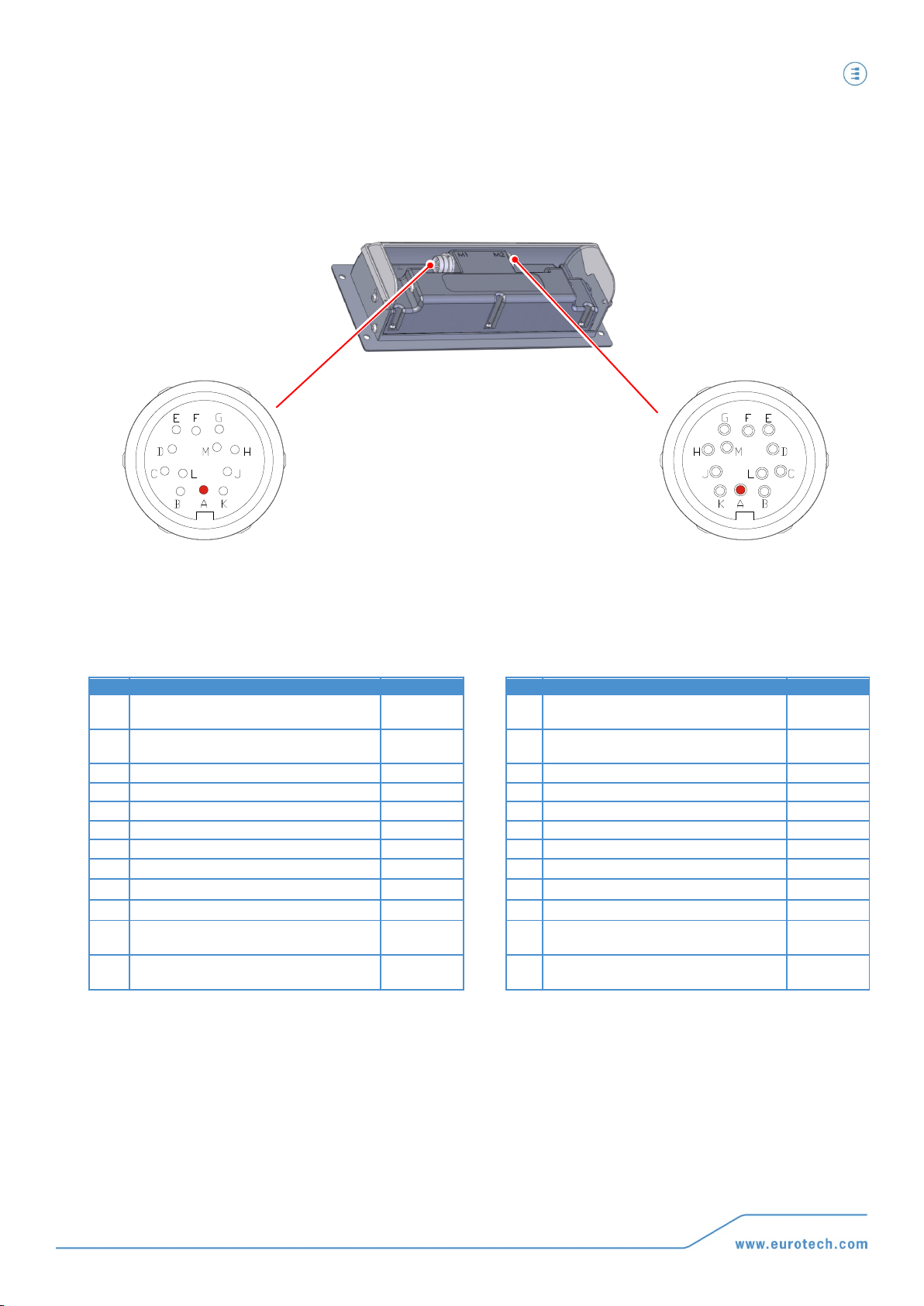
Rear interfaces
The PCN-1001 has the following interface connectors on the rear panel:
M1
M2
CONNECTOR CHARACTERISTICS:
Type: 12-pin male circular connector
P/N: Lumberg 031512
COUNTERPART CHARACTERISTICS:
Type: 12-pin female circular connector
P/N: Lumberg 032212
CONNECTOR CHARACTERISTICS:
Type: 12-pin female circular connector
P/N: Lumberg 031512
COUNTERPART CHARACTERISTICS:
Type: 12-pin male circular connector
P/N: Lumberg 032212
PIN
SIGNAL
DIRECTION
PIN
SIGNAL
DIRECTION
A Power supply + IN
A
Power supply +
(To the secondary PCN-1001 - Wide gate) OUT
B Power supply - IN B Power supply –
(To the secondary PCN-1001 – Wide gate)
OUT
C
Digital IN 1 +
IN
C
Digital OUT 2 V+
OUT
D
Digital IN 1 -
IN
D
Digital OUT 2
OUT
E
Digital OUT 1 V+
OUT
E
Digital IN 2+
IN
F
Digital OUT 1
OUT
F
Digital IN 2-
IN
G
Digital OUT 1 GND
OUT
G
Digital OUT 2 GND
OUT
H
RS485_1 GND
IN/OUT
H
RS485_2 GND IN/OUT
J RS485_1 +
IN/OUT
J RS485_2 + IN/OUT
K
RS485_1 -
IN/OUT
K
RS485_2 -
IN/OUT
L
Power supply +
(For the secondary PCN-1001 - Wide gate)
IN
L Not Connected -
M Power supply –
(For the secondary PCN-1001 – Wide gate) IN M Not Connected -

PCN-1001 general description PCN-1001 User manual
20
PCN-
1001_UserMan_En_4.0
Power Supply Specifications
CHARACTERISTIC
MINIMUM
NOMINAL
MAXIMUM
Power input
9 V dc
12 / 24 V dc
32 V dc
Power consumption
-- -- 15 Watts
Mechanical Characteristics
PCN-1001
Weight:
515 grams
PCN-1001 FRAME
Height:
100 mm
Width:
230 mm
Thickness:
3 mm
REQUIRED CUT OUT DIMENSIONS
Height:
82.0 mm
Width:
208.5 mm
Depth:
41.5 to 70.0 mm, depending on optical panel angle
WARNING!
PROVIDE SUFFICIENT ANCHORAGE WHEN MOUNTING THE PCN-1001.
THIS MUST BE DONE TO ENSURE THAT THE PCN-1001 DOES NOT BECOME DETACHED DURING
TRANSIT CAUSING A SAFETY HAZARD.
Required cut-out dimensions
for mounting
PCN-1001 dimensions
Dimensions are in millimetres
Table of contents
Other Eurotech Cash Counter manuals


