manuals.online logo
Brands
  1. Home
  2. •
  3. Brands
  4. •
  5. Magnescale
  6. •
  7. Cash Counter
  8. •
  9. Magnescale LH71 Series Manual

Magnescale LH71 Series Manual

1/5
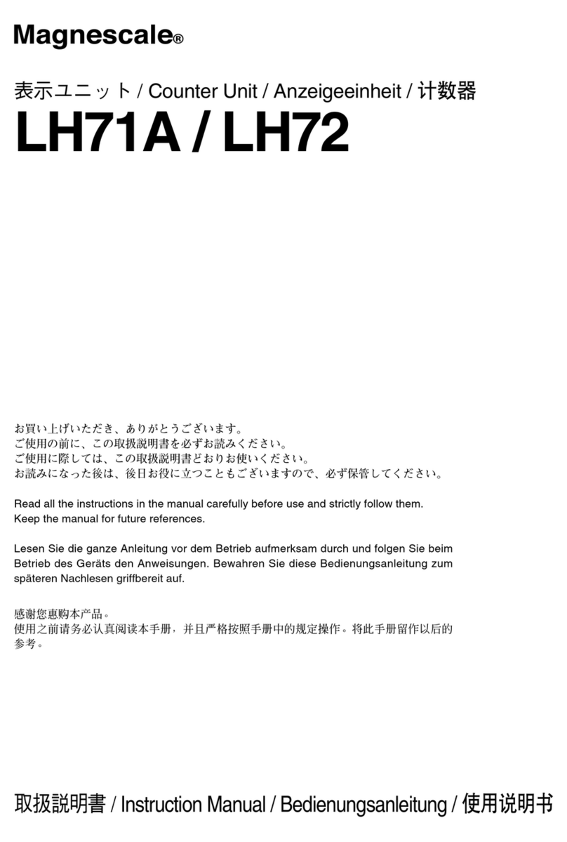
LH71/LH72 Segmented error compensation Setting manual
Ver. 2 (2020.11)
CS&S
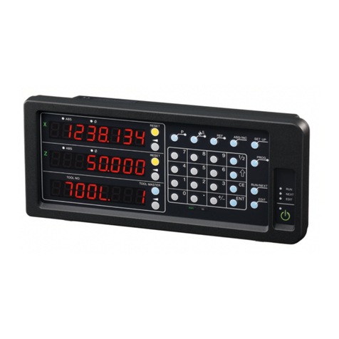
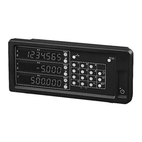
LH71/72
Segmented error
compensation function
Setting manual
2. Setting flow of Segmented error compensation function
This function defines the section within the movable range of the measuring unit and corrects the mechanical error for each section. Since
the compensation value is calculated from the reference point, it is valid only when using the measurement unit with built-in reference
point scale. The range that can correct the segmented error is the range of 7 digits (display resolution) that is displayed based on the
reference point (0) of each axis.
In order to use this function, it is necessary to measure the error between the movement of the machine and the actual movement
(detection amount of the measuring unit) with a laser interferometer or the like in advance. Then, determine the compensation value for
the segmented error from the measurement result, and input the compensation value to the display unit.
After completing the input of the compensation value, perform the reference point reading operation to enable the interval error
compensation. Depending on the tendency of the measured mechanical error, the linear compensation function may be sufficient, so
please judge.
- When the segmented error function is set, the reference point reading mode is automatically entered when the detailed settings are
completed / when the power is turned on / when the error is cleared.
- The compensation value is zero in the area that exceeds the segmented error compensation (the area that exceeds the set range, the
range that cannot be set).
- If the display overflows, the compensation value data will be invalid.
NOTE:
Measurement of mechanical error:
Measure the machine error with a laser interferometer, length reference device, etc. based on the
reference point position (0 mm) of the scale so that the error curve can be visualized.
Creation of compensation data:
Create compensation data by determining compensation points from the visualized error curve.
Input of compensation data:
Input compensation data (compensation point, compensation value) to the display unit
Reference point reading:
Read reference point in reference point mode.
STEP 1
STEP 2
STEP 3
STEP 4
Finished
1. First of all
2/5
LH71/LH72 Segmented error compensation Setting manual
To use the segmented error compensation function, it is necessary to measure the amount of error with the distance actually traveled
with respect to the count value of the measuring unit. To measure the actual distance traveled, use a laser interferometer or the like. The
segmented error function can be used in combination with the scale with built in reference point. The base point for the segmented error
compensation is based on the reference point position of the scale (0 mm).
Changing points Distance Error amount
P1 l 1 ε1
P2 l 2 ε2
P3 l 3 ε3
P4 l 4 ε4
P5 l 5 ε5
Error amount :ε=εM-εC
εM:Master (laser interferometer, etc.)
εC: Count value of display unit
Actually move the stage (or object) and collect the entire error data. Create an error curve from the data and narrow
down the changing points (compensation points) to 32 points or less. If there are two or more axes, consider using
the average value for each axis or narrowing down to the data of frequently used positions.
The measurement range that can correct the segmented
error compensation is the range of 7 digits displayed.
3. Setting of segmented error compensation function
The range of segmented error compensation depends on the minimum resolution
used. In addition, the maximum number of points that can be corrected for section
error is 32 points excluding the reference point. The maximum total compensation
amount is ±600um. The count value of the measuring unit with respect to the actual
distance traveled is affected by the direction of movement of the table and the
change in attitude of the machine due to the movement of the stage.
Measurement unit with built in reference point
Reference point
Resolution Correctable range Compensation
points
0.1um ±999.9999 mm (App. ±1m) Up to 32 points
(Excluding
reference points)
0.5um ±999.9995 mm (App. ±1m)
1.0um ±9999.999 mm (App. ±10m)
10um ±99999.99 mm (App. ±100m)
Drive range matrix on the X-Y axis plane
Reference point position: 0
A finer error curve can be obtained by making the
sampling interval for acquiring error data finer.
Narrow down the changing points of the error curve to 32
points or less. Number from 1 in order from the minus side
or the smallest value.
(Excluding the reference point position)
Measured error curve
Error curve of linear error
Laser interferometer
Moving fixed Laser-head
X axis
Stage
Y axis
If the slope of the error curve is a straight curve,
the linear error compensation function may be
sufficient instead of the segmented error
compensation function. When the changing point is 5 points
Y1
Y2
Y3
X1 X2 X3
+
+
Measurement of mechanical error
Sampling pitch
In the case of X and Y axes,
6 measurements are required,
even if at least the left, right,
and center of each axis are
taken into consideration.
STEP 1
Error amount ε
Error amount ε
Moving distance
Distance traveled based
on the reference point
Distance traveled
based on the
reference point
(l)
Reference point position: 0
Error amount (ε)
l 1
l 2 l 3
l 4
l 5
ε1ε2
ε3
ε4
ε5
P 1
P 2
P 3
P 4
P 5
X
Y1 Data1
Y2 Data2
Y3 data3
X1 X2 X3
Ydata4 data5 data6
3/5
LH71/LH72 Segmented error compensation Setting manual
Create compensation data for the changing points narrowed down to 32 points or less from the error curve measured
in step 1.
* Since the reference point position is 0, it is not included in the compensation points.
Compensation point (P) P1 P2 Reference
point position
P3 P4 P5
Count value of counter unit(l)-500.0000 -125.000 0.000 200.000 414.000 700.000
Lase display value -499.9860 -125.008 0.0000 200.032 414.008 700.020
Compensation amount(ε) 0.014 -0.008 0.0000 0.032 0.008 0.020
Error curve compensation data for the above 5 changing points (Unit: mm)
Changing point:
- Point where the slope of the error curve changes
- Point where the inclination is reversed
Number of points that can be input: up to 32 points
Compensation amount: up to ±600μm
Number the changing point in order from the smallest (or minus) side of the count value of the measurement unit.
Distance traveled
based on the
reference point
(l)
When the changing point is 5 points
Compensation point input number
Compensation amount at compensation point
Position data of compensation point
Creation of compensation data
STEP 2
Reference point position: 0
Number the changing point in order from the smallest (or minus) side of the count value of the measurement unit. If the start position of
the segmented error compensation is position 1 and the end position is position N, the position N should be 32 or less.
The maximum compensation value for the entire changing point is within ±600μm. If it exceeds the ±600μm range, the segmented
error compensation function cannot be used.
NOTE:
- The segmented error compensation function is applied to the range from the start position (ε 1) to the end position (ε n).
- Input compensation data cannot be handled below the unit of input resolution of the measurement unit.
Error amount (ε)
l 1
l 2 l 3
l 4
l 5
ε1ε2
ε3
ε4
ε5
P 1
P 2
P 3
P 4
P 5
4/5
LH71/LH72 Segmented error compensation Setting manual
⑤Repeat ③and ④and enter all the required position data and compensation values.
Press key again to finish entering the axis. You can also select it with key when you want to reset it.
Press key to exit the detailed setting mode
and enter the reference point mode to enable the segmented error compensation function.
③When you press key of the axis to enter the compensation value, the input display is displayed.
→
Enter the position data for the position number with the numeric keys.→
Press key to save the position information.
④Next, the input display of the compensation value is displayed.
Enter the compensation value with the numeric keys → →
Press the key to save the compensation value.
②Press key to display the input of the error compensation function. →
Press key to select (Segmented error compensation) and press key.→
①With the display unit in the normal counting state, press key to enter the advanced setting mode.
The display will be .
(Example: -190.000)
(Example:0.007)Automatically moves
to the next input point
(Position 1)
Enter the compensation data created in step 2 into the display unit.
Detailed Settings
Input of compensation data
Continue to step 4
STEP 3
Error Setting
Compensation value
Segmentation Error
Segmented error compensation
No compensation
Error compensation off
Linear compensation
Linear Error
Segmented error compensation
Segmentation Error
Selection of error compensation function
default
5/5
LH71/LH72 Segmented error compensation Setting manual
Continued from step 3
It is necessary to always detect the reference point in order to enable the segmented error compensation function.
* Segmented error compensation is calculated based on the reference point of the measurement unit .
⑥Press key when the power is turned on or after setting the interval error compensation value to enter the
reference point acquisition mode.
key lamp is lit, the axis label lamp is blinking, and the display is .
⑦When you press key of the axis to get the reference point, the display and the axis label blink.
You can also acquire the reference point of two or more axes at the same time.
Blinking
⑧Move the measuring unit to pass the reference point.
The display changes from blinking to lit, and reference point acquisition is completed.
NOTE: When using the measurement unit for unidirectional reference point detection, move the
measurement unit in the direction opposite to the direction in which the reference point is passed. (Not
required for bidirectional detection)
Reference point reading
LH71A-3, XYZ axis refrence point acquisition
Press the key
Reference point
Axis label
STEP 4
Finished

Other manuals for LH71 Series

4

This manual suits for next models

1

Other Magnescale Cash Counter manuals

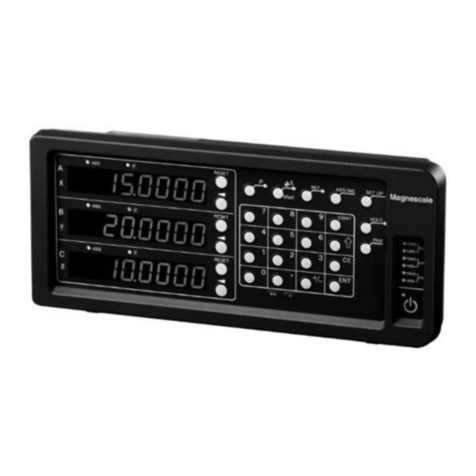
Magnescale LT10A-105 User manual

Magnescale

Magnescale LT10A-105 User manual

Magnescale LH70 Manual

Magnescale

Magnescale LH70 Manual

Magnescale LH71A User manual

Magnescale

Magnescale LH71A User manual

Magnescale LH70 User manual

Magnescale

Magnescale LH70 User manual

Magnescale LY72 User manual

Magnescale

Magnescale LY72 User manual

Magnescale LH71 Series User manual

Magnescale

Magnescale LH71 Series User manual

Magnescale LH71 Series User manual

Magnescale

Magnescale LH71 Series User manual

Magnescale LG20 User manual

Magnescale

Magnescale LG20 User manual

Magnescale LH72 User manual

Magnescale

Magnescale LH72 User manual

Magnescale LH70 User manual

Magnescale

Magnescale LH70 User manual

Magnescale LG20 Manual

Magnescale

Magnescale LG20 Manual

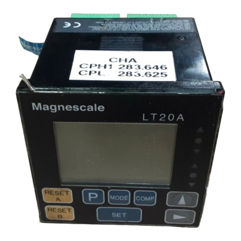
Magnescale LT20A Series User manual

Magnescale

Magnescale LT20A Series User manual

Magnescale LG20 User manual

Magnescale

Magnescale LG20 User manual

Popular Cash Counter manuals by other brands

Amrotec S-200 Assembly instructions

Amrotec

Amrotec S-200 Assembly instructions

Danaher Veeder-Root C346 Series Technical manual

Danaher

Danaher Veeder-Root C346 Series Technical manual

Generix PROMNICO user manual

Generix

Generix PROMNICO user manual

NanoEnTek Adam rWBC2 instruction manual

NanoEnTek

NanoEnTek Adam rWBC2 instruction manual

AQ-Tron BAT/32562 Technical manual

AQ-Tron

AQ-Tron BAT/32562 Technical manual

Premax PM-CC35D Operation manual

Premax

Premax PM-CC35D Operation manual

WOBIT MD150E instruction manual

WOBIT

WOBIT MD150E instruction manual

Polar Electro GD882 instruction manual

Polar Electro

Polar Electro GD882 instruction manual

Velleman Modules VM107 manual

Velleman Modules

Velleman Modules VM107 manual

Amrotec MiB-11V Service manual

Amrotec

Amrotec MiB-11V Service manual

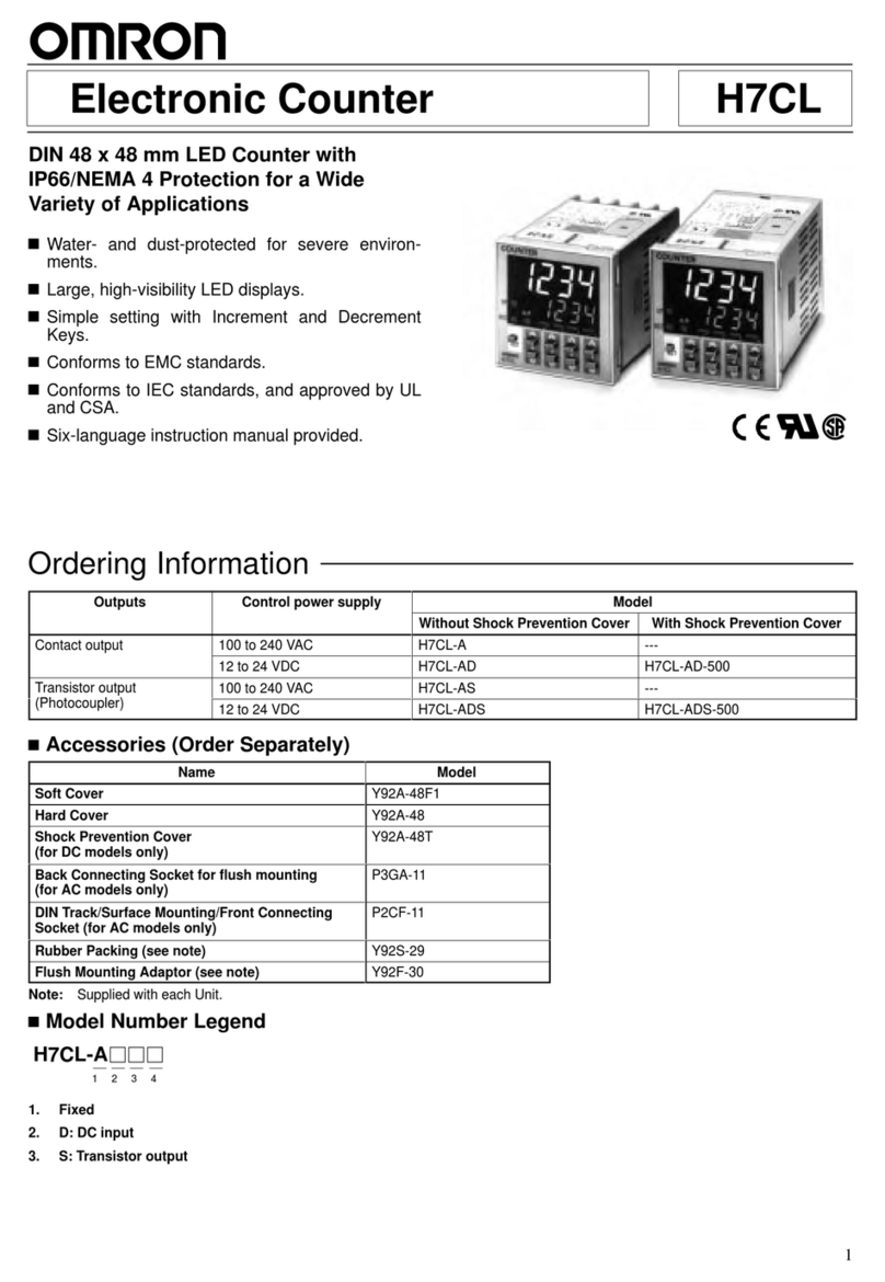
Omron H7E-P Series quick start guide

Omron

Omron H7E-P Series quick start guide

MULTISPAN PIC-9004 operating manual

MULTISPAN

MULTISPAN PIC-9004 operating manual

Sun-Tech ST-290PC user manual

Sun-Tech

Sun-Tech ST-290PC user manual

DESIGN CONCEPTS 804 quick start guide

DESIGN CONCEPTS

DESIGN CONCEPTS 804 quick start guide

Glas Craft Probler P2 user manual

Glas Craft

Glas Craft Probler P2 user manual

CashConcepts CCE 315 BASE quick start guide

CashConcepts

CashConcepts CCE 315 BASE quick start guide

red lion CUB2L8 quick start guide

red lion

red lion CUB2L8 quick start guide

CashConcepts CCE 335 user manual

CashConcepts

CashConcepts CCE 335 user manual

manuals.online logo
manuals.online logoBrands
  • About & Mission
  • Contact us
  • Privacy Policy
  • Terms and Conditions

Copyright 2025 Manuals.Online. All Rights Reserved.