Arrow International PrecisionCounter 500 User manual

Service Manual
This service manual is only authorized for use by Arrow Distributors
Revision 1.12089

1. Overview of Parts and Procedures .................................................................. 4
2. Disassembly ................................................................................................................ 16
a. Remove the column .................................................................................... 16
b. Remove the ticket catcher assembly ........................................................ 17
c. Remove the metal film retainer and metal ticket guide .......................... 19
d. Remove the plastic body ............................................................................ 19
e. Remove the metal top wrap ....................................................................... 22
f. Remove the metal side wall ....................................................................... 23
g. Partial disassembly ..................................................................................... 26
3. Procedures ................................................................................................................... 28
1. Adjusting the metal ticket guide ............................................................... 28
2. Adjusting the ticket catcher assembly ..................................................... 30
3. Adjusting the mylar ticket deflector ......................................................... 31
4. Replacing the mylar ticket deflector ........................................................ 32
5. Replacing the ticket catcher sensor ......................................................... 33
6. Adjusting the ticket gate ............................................................................ 34
7. Replacing the square pushbutton switch ................................................. 36
8. Replacing the keypad ................................................................................. 37
9. Replacing the LCD assembly ..................................................................... 38
10. Adjusting the metal spring foot ................................................................. 40
11. Cleaning the ticket-count optical sensor ................................................. 41
12. Replacing a plastic gear ............................................................................ 42
13. Replacing a roller ........................................................................................ 43
14. Replacing the ticket-count optical sensor ............................................... 44
15. Replacing the motor belt ............................................................................ 46
16. Replacing the plastic pulley ...................................................................... 47
17. Replacing the motor ................................................................................... 48
18. Cleaning the rollers .................................................................................... 50
19. Diagnosing power issues ........................................................................... 51
Table of Contents

LEGAL NOTICE
This document is provided “AS IS” and Arrow International, Inc. and its affiliated companies
(collectively, “Arrow”) assume no responsibility for any typographical, technical, or other
inaccuracies in this document. In order to protect Arrow proprietary and confidential information
and/or trade secrets, this document may describe some aspects of Arrow technology in
generalized terms. Arrow reserves the right to periodically change information that is contained
in this document; however, Arrow makes no commitment to provide any such changes, updates,
enhancements, or other additions to this document to you in a timely manner or at all.
ARROW MAKES NO REPRESENTATIONS, WARRANTIES, CONDITIONS, OR COVENANTS,
EITHER EXPRESS OR IMPLIED (INCLUDING WITHOUT LIMITATION, ANY EXPRESS OR
IMPLIED WARRANTIES OF FITNESS FOR A PARTICULAR PURPOSE, NON-INFRINGEMENT,
MERCHANTABILITY, DURABILITY OR TITLE) AS TO THE PERFORMANCE OF THE
PRECISIONCOUNTER 500 (THE “EQUIPMENT”) OR ANY RELATED EQUIPMENT OR SERVICE EXCEPT
FOR THE “PrecisionCounter 500™ Limited Warranty” SET FORTH IN THE OWNER’S MANUAL (a
copy of which is available upon request from Arrow).
IN CONNECTION WITH YOUR USE OF THIS DOCUMENTATION, NEITHER ARROW NOR ITS
RESPECTIVE DIRECTORS, OFFICERS, EMPLOYEES, OR CONSULTANTS SHALL BE LIABLE TO YOU
FOR ANY DAMAGES WHATSOEVER BE THEY DIRECT, ECONOMIC, COMMERCIAL, SPECIAL,
CONSEQUENTIAL, INCIDENTAL, EXEMPLARY, OR INDIRECT, EVEN IF ARROW HAS BEEN ADVISED
OF THE POSSIBILITY OF SUCH DAMAGES. IN NO EVENT WILL ARROW’S LIABILITY IN CONNECTION
WITH THE EQUIPMENT OR ANY RELATED SERVICE EXCEED THE SALES PRICE PAID FOR THE
EQUIPMENT.
Part number: 46731-MNL2
Revision 1.12089
March 2012
© 2012 Arrow International, Inc.
9900 Clinton Rd. Cleveland, OH 44144 • Toll Free: 800.321.0757
Technical Assistance Center (8 AM - 12AM EST): 800.277.6214
This service manual is only authorized for use by Arrow Distributors
This manual should not be reproduced in any manner without written consent from Arrow International, Inc.

#1 Overview of Parts* and ProceduresChapter
3434
Adjusting the ticket gate
2828
Adjusting the metal ticket guide
3838
Replacing the LCD assembly
3737
Replacing the keypad
3636
Replacing the square pushbutton switch
Square Pushbutton Switch
Keypad
LCD Assembly (display)
Plastic - Main Body
Metal - Ticket Guide
Ticket Gate & Metal Ticket Gate Edge
Column
* For replacements: contact the Arrow Technical Assistance Center, at 800.277.6214 and refer to the part name.
A technician will provide you with the current part number or will place an order for that part
OVERVIEW OF PARTS AND PROCEDURES CHAPTER 1
www.arrowinternational.com
4
© 2012 Arrow International, Inc.
9900 Clinton Rd. Cleveland, OH 44144 • Toll Free: 800.321.0757
Technical Assistance Center (8 AM - 12AM EST): 800.277.6214
This service manual is only authorized for use by Arrow Distributors
ARROW INTERNATIONAL
5

3131
Adjusting the mylar ticket deflector
3333
Replacing the ticket catcher sensor
Power Entry Module (the fuse is located in this component)
Wire Harness for the Ticket Catcher Optical Sensor
Ticket Catcher Optical Sensor
Ticket Catcher Assembly (hopper)
Mylar - Ticket Deflector
Metal - Film Retainer
Thumb Nut 6-32 - Knurled Brass
3030
Adjusting the ticket catcher assembly
3232
Replacing the mylar ticket deflector
3434
Adjusting the ticket gate
Metal - Mounting Bracket for the Ticket Catcher Assembly
Serial number of the ticket counter:
Have available when calling the Technical Assistance Center
OVERVIEW OF PARTS AND PROCEDURES CHAPTER 1
www.arrowinternational.com
6
© 2012 Arrow International, Inc.
9900 Clinton Rd. Cleveland, OH 44144 • Toll Free: 800.321.0757
Technical Assistance Center (8 AM - 12AM EST): 800.277.6214
This service manual is only authorized for use by Arrow Distributors
ARROW INTERNATIONAL
7

4242
Replacing a plastic gear
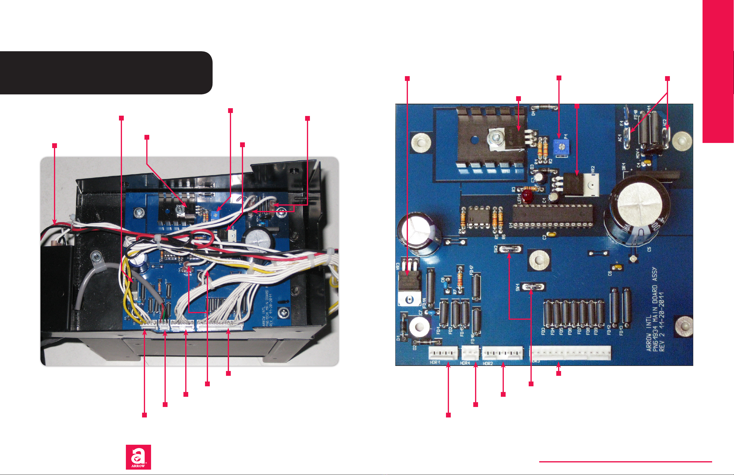
Harness for the square pushbutton switch: 2 variants may exist in the field. Both variants uti-
lize 2 wires for sending the switch signal, and those 2 wires connect to SW1 and SW2 on the
Main PCB (it doesn’t matter which wire connects to which connector). The 1st variant consists
of just the 2 wires connecting to the pushbutton switch. The 2nd variant, utilizes a 5-prong
plug to connect to the pushbutton switch. This 5-prong plug, has 3 extra prongs for possible
expanded functionality in future models of the ticket counter
7-pin harness for the keypad - Connects to HDR2 on the main PCB (underneath the ticket coun-
ter). The header which connects to the keypad itself is not keyed. Prior to removal, it is recom-
mended that both the header and connector on the keypad be marked in some way to ensure
correct re-attachment: in the diagram, the header has a black mark indicating the location of
PIN 1 ... the keypad connector (not visible) has a similar marking
Power wires for the motor - they go underneath the ticket counter, across the main PCB, and
connect to the motor on the other side of the ticket counter (see p.10-11)
Motor Board PCB
Plastic Gear - 60 Tooth. It is mounted on the transfer shaft (which does not contain any rollers)
Plastic Gear - 96 Tooth. It is mounted on the shaft with the two visible rollers
The optical sensor responsible for counting tickets includes these 4 wires pre-attached (con-
sisting of 2 braids [red/black & orange/black]). The other ends of the wires are soldered to the
motor board PCB (which is visible on this page)
4141
Cleaning the ticket-count optical sensor
Plastic Gear - 35 Tooth. It is mounted on the motor shaft
5-pin harness for the motor board PCB - Connects to HDR1 on the main PCB (underneath the
ticket counter). This harness has a keyed header on both ends that snaps into place when
inserted correctly
4444
Replacing the ticket-count optical sensor
14-pin harness for the LCD assembly - Connects to HDR3 on the main PCB (underneath the
ticket counter). This harness has a keyed header on both ends that snaps into place when
inserted correctly
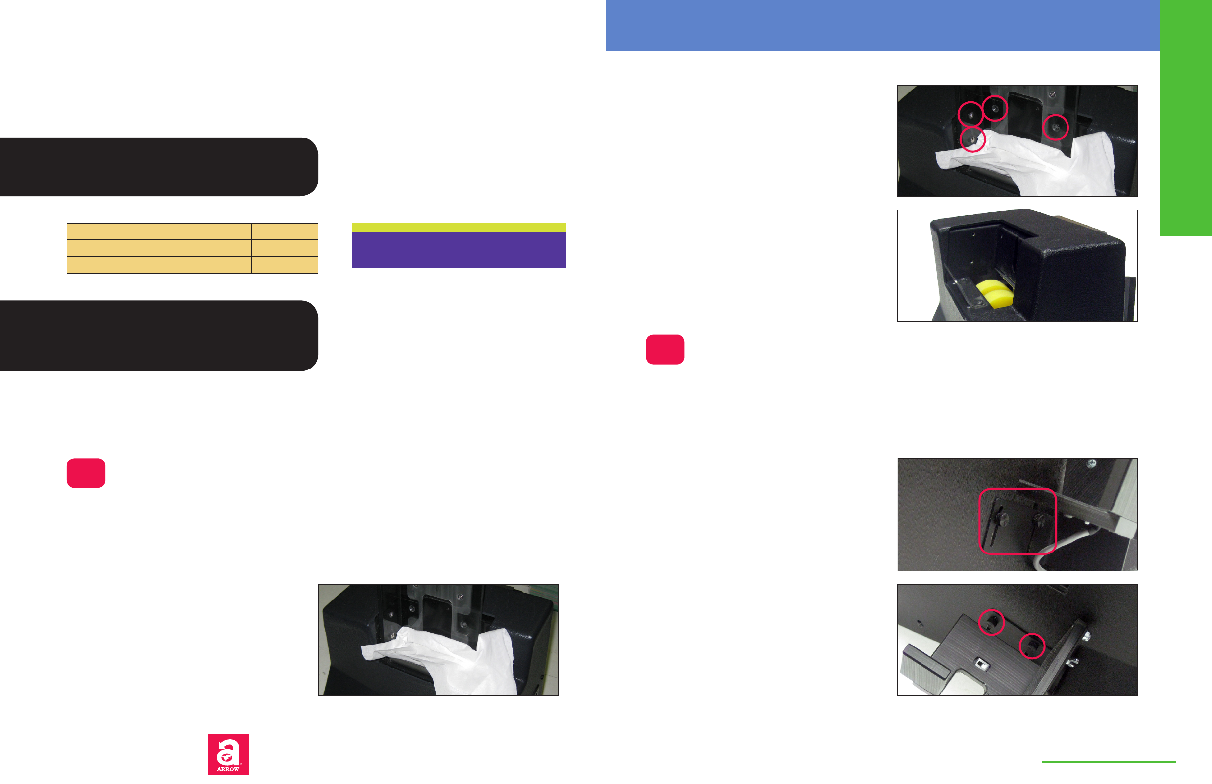
There is an interlocking mechanism between
the header on the harness and the header on
the PCB. This results in a very solid connec-
tion, but, it can also make it seem difficult to
disconnect the harness from the PCB
The following notes should be followed when
disconnecting the harness from the PCB
• make sure there is enough room to
comfortably grip the harness header
• grip the harness header from the left
and right plastic sides of the connector
(not from the wires) and pull the con-
nector straight backwards (red arrow)
OVERVIEW OF PARTS AND PROCEDURES CHAPTER 1
www.arrowinternational.com
8
© 2012 Arrow International, Inc.
9900 Clinton Rd. Cleveland, OH 44144 • Toll Free: 800.321.0757
Technical Assistance Center (8 AM - 12AM EST): 800.277.6214
This service manual is only authorized for use by Arrow Distributors
ARROW INTERNATIONAL
9

Arrow International cannot guarantee that the original trans-
former is present in a machine at the time of repair, or that the
wiring has not been tampered with. When working with power,
always verify the connections on both the transformer and the
power entry module. Also verify that the outlet used by the ticket
counter does not have its hot/neutral/ground pins reversed or
disconnected
4747
Replacing the plastic pulley
Motor - Column Drive
Gear - Plastic Pulley
O-ring Motor Belt
4848
Replacing the motor
4646
Replacing the motor belt
Transformer: current model # 4-49-5016 (see label on top of transformer)
Motor Bracket
5) Double spade (both brown)
• Jump to # 2
• ‘Line in’ from power entry module
4) Jump from #1 (blue)
3) (Empty)
2) Jump from #5 (brown)
1) Double spade (both blue)
• ‘Neutral’ from power entry
module
• Jump to #4
(10
(9
(8
(7
(6
(white) To AC1 or AC2 on main
PCB (doesn’t matter which since
rectification is performed on the
main PCB itself)
(black) Jump to # 7
(Empty)
(black) Jump from # 9
(white) To AC1 or AC2 on main
PCB (doesn’t matter which since
rectification is performed on the
main PCB itself)
Power wires for the motor - connect to other side of machine (see p.7)
Ground
Line-in
Neutral
115 VAC in ... 18 VAC out
OVERVIEW OF PARTS AND PROCEDURES CHAPTER 1
www.arrowinternational.com
10
© 2012 Arrow International, Inc.
9900 Clinton Rd. Cleveland, OH 44144 • Toll Free: 800.321.0757
Technical Assistance Center (8 AM - 12AM EST): 800.277.6214
This service manual is only authorized for use by Arrow Distributors
ARROW INTERNATIONAL
11

The optical sensor responsible for counting tickets includes 4 wires pre-attached (consisting of
2 braids [red/black & orange/black]). The other ends of the wires are soldered to the motor
board PCB (see p. 8-9)
4141
Cleaning the ticket-count optical sensor
4444
Replacing the ticket-count optical sensor
Roller Core (for 1” rollers)
1” Roller
2” Roller
Shaft Drive (Transfer): 6” long
Shaft Drive (Motor): 7” long
Shaft Collar
Clip Bearing
5050
Cleaning the rollers
4343
Replacing a roller
Foot Mounting Bracket
4040
Adjusting the metal spring foot
Metal Spring Foot
Roller Core (for 2” rollers)
OVERVIEW OF PARTS AND PROCEDURES CHAPTER 1
www.arrowinternational.com
12
© 2012 Arrow International, Inc.
9900 Clinton Rd. Cleveland, OH 44144 • Toll Free: 800.321.0757
Technical Assistance Center (8 AM - 12AM EST): 800.277.6214
This service manual is only authorized for use by Arrow Distributors
ARROW INTERNATIONAL
13

Ticket counter is positioned upside down,
exposing the main PCB underneath
Transformer side
CAUTION: When performing repairs & maintenance on the
PrecisionCounter 500, various jagged metal edges may be ex-
posed. These can cause personal injury or damage to property
if not properly accounted for
HDR1 - 5-pin - motor board PCB
HDR4 - 3-pin - ticket catcher optical sensor
HDR2 - 7-pin - keypad
HDR3 - 14-pin - LCD assembly
AC1 & AC2 - AC inputs
from transformer ...
order doesn’t matter
P1 - potentiometer (variable resis-
tor controls motor speed - factory
set for motor to receive 14.2 VDC)
VR3 - 5 VDC voltage
regulator for LCD
assembly
VR1 - voltage regula-
tor for motor: 14.2 VDC if
potentiometer is set correctly
SW1 & SW2 - pushbutton switch ... order doesn’t matter
VR2 - 5 VDC voltage
regulator for processor
Motor board PCB
Ticket catcher optical sensor
Keypad
LCD assembly
Pushbutton switch ... order doesn’t matter
AC inputs from transformer
... order doesn’t matter
Potentiometer
5 VDC voltage regula-
tor for LCD assembly
Voltage regulator for motor 5 VDC voltage regu-
lator for processor
Red & Black wires from
motor to motor board PCB
OVERVIEW OF PARTS AND PROCEDURES CHAPTER 1
www.arrowinternational.com
14
© 2012 Arrow International, Inc.
9900 Clinton Rd. Cleveland, OH 44144 • Toll Free: 800.321.0757
Technical Assistance Center (8 AM - 12AM EST): 800.277.6214
This service manual is only authorized for use by Arrow Distributors
ARROW INTERNATIONAL
15

Chapter #2 Disassembly
This chapter documents the common steps needed to begin all internal repairs of the PrecisionCounter 500.
Most procedures outlined in Chapter 3 will refer to this disassembly process and will state which steps
should have been completed before the procedure can begin
CAUTION: To prevent the risk of electrocution, unplug the
unit prior to performing maintenance. Failure to disconnect
power could result in injury and/or death, and possible dam-
age to the PrecisionCounter 500
Estimated Time 15 minutes
Difficulty 3 of 5
Possibility of damage 3 of 5
All procedure estimates assume a technician of average
skill who has only performed this process 1 or 2 times, and is
moving at a relatively cautious speed
Tools Required:
• #1 Phillips screwdriver (capable of
comfortably handling size 6 screws)
Figure 2.1
Use a cloth or paper towel to cover the gaps
Figure 2.3
With the column removed
Figure 2.4
Notice the angle of the thumb nuts
Figure 2.2
Remove these 4 screws
Remove the column
1) (Optional, but recommended) - use a cloth or paper
towel to cover the gaps through which a screw might
fall into the inner chamber of the machine
2) Remove the 4 screws which hold the column to
the main body of the ticket counter. The screws may
not be magnetic: do not rely on a magnetic-tip driver
to prevent a screw from falling. The order does not
matter but the last screw will have a lot of torque on
it from the weight of the column. Make sure to sup-
port the column with your hand as you remove the
last screw
Remove the ticket catcher assembly
4) If possible, take note of the angle at which the as-
sembly is currently attached to the main body (each
owner will customize this for his/her needs and the
results may vary)
3) Remove the cloth/paper towel and set aside the
column with its 4 screws
Figure 2.5
Remove the two thumb nuts
5) Remove the two thumb nuts which hold the as-
sembly to the main body. Gently lift the assembly to
alleviate any torque on the thumb nuts: it can help a
great deal
The ticket counter will then be easier to handle and can even be positioned upside down
A
B
www.arrowinternational.com
DISASSEMBLY CHAPTER 2
16
© 2012 Arrow International, Inc.
9900 Clinton Rd. Cleveland, OH 44144 • Toll Free: 800.321.0757
Technical Assistance Center (8 AM - 12AM EST): 800.277.6214
This service manual is only authorized for use by Arrow Distributors
ARROW INTERNATIONAL
17

6) Let the assembly rest on the table, but ...
Figure 2.6
Let the assembly rest on the table, but ...
7) ... do not forget that the harness for the ticket
catcher sensor is still attached
Figure 2.7
... do not forget that the harness for the ticket catcher sensor is still attached
8) The harness can be pulled out (there is no catch
that holds it in place). When it is later re-inserted,
however, it must be inserted as oriented in the pic-
ture (with the notch being visible)
Figure 2.8
Slide the connector out of the sensor
9) Leave the harness positioned as in the picture. In
later steps it will be necessary to pull it further inside
the plastic body, in order to lift the plastic body off the
metal body of the ticket counter
Figure 2.9
With the ticket catcher assembly removed
Remove the metal film retainer and metal
ticket guide
10) Before removing the metal film retainer take note
of how much of the ticket exit chute is covered by the
mylar film. In most cases, the mylar film should just
reach the metal of the ticket exit chute
Unscrew the two screws and remove the retainer
and the film that is attached to the retainer
Figure 2.10
Remove the metal film retainer
11) Before removing the metal ticket guide, take note
of which position it is screwed into: the metal ticket
guide can be adjusted for various ticket widths by be-
ing screwed further in, or away, from the column
Unscrew the two screws and remove the ticket guide
Figure 2.11
Remove the metal ticket guide
12 )The plastic body is attached to the rest of the ma-
chine with 4 screws on each side ...
Figure 2.12
Remove these 4 screws on each side
Remove the plastic body
C
D
www.arrowinternational.com
DISASSEMBLY CHAPTER 2
18
© 2012 Arrow International, Inc.
9900 Clinton Rd. Cleveland, OH 44144 • Toll Free: 800.321.0757
Technical Assistance Center (8 AM - 12AM EST): 800.277.6214
This service manual is only authorized for use by Arrow Distributors
ARROW INTERNATIONAL
19

15) Only lift the plastic body a few inches ... it will
not go any further because it is restricted by cable
lengths in the following locations:
• back - power cables and wire harness for the
ticket catcher optical sensor
• front - harnesses for pushbutton, LCD assembly,
and keypad
1 set of cables will need to be removed to lift the plas-
tic body: in this manual, the front cables are removed
Figure 2.15
Partially lift the plastic body
16) Pull back on the wire harness for the ticket catch-
er optical sensor to get some slack. You shouldn’t
need to pull it out all the way: the rest of this manual
proceeds under the assumption that both the sensor
harness and the power cables are long enough that
they do not need to be removed (individual machines
may vary)
Figure 2.16
Get some slack on the wire harness
17) Note: steps 17-20 can be performed in any order ...
disconnect the shortest cables first, in order to allow
greater range of motion when pulling out the remain-
ing cables
Reach through the top of the plastic body and pull out
the connector for the LCD assembly. This keyed con-
nector will be tough to pull out if the plastic body is
not lifted enough: pull from the sides, not on the wires
Figure 2.17
Pull out the connector for the LCD Assembly
18) There are two options for disconnecting the key-
pad connector. It can also be removed by reaching
through the top of the plastic body (be careful not to
snag the LCD assembly connector), but ...
Figure 2.18
Option #1 for disconnecting the keypad connector
19) ... some might find it easier to disconnect the key-
pad connector by reaching underneath the plastic
body (in the bottom right of Figure 2.15)
Whichever option you use, be aware that the keypad
connector is not keyed (see p. 9) and take precaution-
ary steps to make sure you can reinsert it correctly
Figure 2.19
Option #2 for disconnecting the keypad connector
20) The final component that needs to be discon-
nected before the plastic body can be lifted is the
square pushbutton switch. The switch has 5 prongs,
but is connected to the machine with only 2 wires.
The 2 wires are interchangeable, but they must be
connected to the 2 prongs shown in Figure 2.20. The
switch be accessed by reaching underneath the
plastic body (in the bottom right of Figure 2.15)
Figure 2.20
A close-up of the connector for the square pushbutton switch
21) Since the cables in the back of the ticket counter
are still connected, keep the back of the plastic body
at a steady height of 5 inches, and use it as a hinge on
which to swing the plastic body upwards in the front
Figure 2.21
Use this motion to lift the plastic body
22) View #1 of the metal body of the ticket counter (on
the left) set beside the plastic body (notice the two
sets of cables which are still attached)
Figure 2.22
View #1 of the metal body of the ticket counter
13) ... and 1 screw in the back: remove all 9 screws
Figure 2.13
Remove this screw in the back as well
14) Note: the studs to which the ticket catcher as-
sembly thumb nuts mount will also prevent the plastic
body from being lifted off the metal body of the ticket
counter. Before step #15 can be performed, it will be
necessary to ‘tuck the studs into’ the plastic body’ by
gently pulling the plastic body over the studs
Figure 2.14
Gently pull the plastic body over these 2 studs
www.arrowinternational.com
DISASSEMBLY CHAPTER 2
20
© 2012 Arrow International, Inc.
9900 Clinton Rd. Cleveland, OH 44144 • Toll Free: 800.321.0757
Technical Assistance Center (8 AM - 12AM EST): 800.277.6214
This service manual is only authorized for use by Arrow Distributors
ARROW INTERNATIONAL
21

23) View #2 of the metal body of the ticket counter
The metal body of the ticket counter is resting on a
metal pan. Of the screws you removed in step # 12,
2 - on each side of the ticket counter - drilled into the
metal body, and the other 2 drilled into the metal pan.
By completing step #12 you simultaneously detached
not only the plastic body, but also the metal pan, from
the metal body of the ticket counter ... so ...
Figure 2.23
View #2 of the metal body of the ticket counter
24) ... you can now lift the metal body of the ticket
counter out of the bottom metal pan
Figure 2.24
Lift the metal body from the bottom metal pan
Remove the metal top wrap
25) The metal top wrap protects the ticket-count opti-
cal sensor and provides 2 of the 4 mounting points for
the column
Figure 2.25
The metal top wrap
26) Remove these 3 screws on the side of the ticket
counter which has the motor
Figure 2.26
Remove these 3 screws
27) Remove these 3 screws on the side of the ticket
counter which has the motor board PCB
Figure 2.27
Remove these 3 screws
28) Lift the metal top wrap from the metal body of the
ticket counter
Figure 2.28
Lift the metal top wrap
29) With the metal top wrap removed, the ticket-count
optical sensor is now accessible for service
Figure 2.29
With the metal top wrap removed
Remove the metal side wall
30) The metal side wall is a large component of the
metal body of the ticket counter. It provides the
mounting point for the metal ticket guide and restricts
access to the inner components
Figure 2.30
The metal side wall
E
F
www.arrowinternational.com
DISASSEMBLY CHAPTER 2
22
© 2012 Arrow International, Inc.
9900 Clinton Rd. Cleveland, OH 44144 • Toll Free: 800.321.0757
Technical Assistance Center (8 AM - 12AM EST): 800.277.6214
This service manual is only authorized for use by Arrow Distributors
ARROW INTERNATIONAL
23

31) Remove these 2 screws on the side of the ticket
counter which has the motor board PCB
Figure 2.31
Remove these 2 screws
32) Remove these 2 screws on the side of the ticket
counter which has the motor
Figure 2.32
Remove these 2 screws
33) Pull the metal side wall from the rest of the body
of the ticket counter. Because of the precise fitting
design, there will still be some pressure exerted on
the metal side wall from the surrounding metal en-
closure
Figure 2.33
Pull out the metal side wall
34) The inside chamber of the ticket counter is re-
vealed once the metal side wall is removed
Common disassembly for most procedures stops at -
or before - this point
Figure 2.34
The inside chamber of the ticket counter
Re-assembly can be performed by following the previous procedure in reverse
• Attach the metal side wall
• Attach the metal top wrap
• Attach the plastic body
• Attach the metal film retainer and metal ticket guide
• Attach the ticket catcher assembly
• Attach the column
• Plug in the power cord and
turn on the power
• Test the operation of the machine
Because of the precise-fitting metal construction of the ticket
counter, attempting to re-assemble the machine with a power
tool can result in stripping of the screws/sockets if the align-
ment is improper (metal is not as accommodating as wood to
overpowering force). We recommend that all the long screws
for a particular step, first be inserted 1/3 of the way, and then
- only once the first step is complete - be fully screwed in: if
necessary, use a screwdriver to correct improper alignment
Power tool torque settings should not exceed level 4 for metal
and level 3 for the plastic column
www.arrowinternational.com
DISASSEMBLY CHAPTER 2
24
© 2012 Arrow International, Inc.
9900 Clinton Rd. Cleveland, OH 44144 • Toll Free: 800.321.0757
Technical Assistance Center (8 AM - 12AM EST): 800.277.6214
This service manual is only authorized for use by Arrow Distributors
ARROW INTERNATIONAL
25

Partial disassembly
By removing the bottom metal pan, it is possible to access the bottom inner chamber of the ticket
counter without removing the plastic body or any of the external components (column, ticket catcher
assembly, metal ticket guide, and metal film retainer). Partial disassembly is useful for replacing
the keypad, pushbutton switch, main PCB, or for diagnosing power issues. For all other procedures
that involve internal repairs, you will still need to perform the complete disassembly process as de-
scribed up to this point
G
35) Remove these 2 screws on each side ...
Figure 2.35
Remove these 2 screws on each side
36) ... and the screw in the back
These 5 screws hold the bottom metal pan to the
plastic body
Figure 2.36
Remove this screw in the back as well
37) The metal pan can then be removed by resting the
machine on its rear side and pulling out the bottom
metal pan
Note: resting the machine as in Figure 2.37, is the ideal
end position for partial disassembly: though it seems
as if the column is touching the desk, it is actually a
few millimeters above it, and the entire weight of the
ticket counter is supported on the plastic body
Figure 2.37
The ideal end position for partial disassembly
38) Resting the machine on its rear side provides ac-
cess to the following components
Figure 2.38
2.37’s position allows access to the following components
39) The ticket counter can also rest on the side that
does not have the ticket catcher assembly ...
Figure 2.39
The ticket counter resting on the side that does not have the ticket catcher assembly
40) ... however, extra caution must be taken to not
leave the machine too long in this position, or to pro-
vide a cushion underneath the metal ticket guide
(because it is one of the two support points for this
position)
Figure 2.40
The 2 support points when the ticket counter is laying on its side
41) Having the ticket counter rest on its side, may
provide easier access to some components
Figure 2.41
A view of the inner components when the ticket counter is resting on its side
42) For the small added effort of removing the column
(disassembly steps 1-3), the ticket counter can also
be set to rest on its top ...
Figure 2.42
Remove the column to allow the ticket counter to be laid upside down
43) ... providing, possibly, the best access to compo-
nents of all the partial disassembly positions
Figure 2.43
A view of the inner components when the ticket counter is resting upside down
www.arrowinternational.com
DISASSEMBLY CHAPTER 2
26
© 2012 Arrow International, Inc.
9900 Clinton Rd. Cleveland, OH 44144 • Toll Free: 800.321.0757
Technical Assistance Center (8 AM - 12AM EST): 800.277.6214
This service manual is only authorized for use by Arrow Distributors
ARROW INTERNATIONAL
27

Disassembly - the steps in chapter 2 that need to be completed before a
procedure can begin. N/A means that disassembly is not applicable/not
needed. Only Partial means that only partial disassembly - section G of
chapter 2 - needs to be completed
Disassembly 1-22, for example, means that steps 1-22
of disassembly should be completed before beginning
the procedure (up to the point in the attached image)
15) Only lift the plastic body a few inches ... it will
not go any further because it is restricted by cable
lengths in the following locations:
• back - power cables and wire harness for the
ticket catcher optical sensor
• front - harnesses for pushbutton, LCD assembly,
and keypad
1 set of cables will need to be removed to lift the plas
-
tic body: in this manual, the front cables are removed
Figure 2.15
Partially lift the plastic body
16) Pull back on the wire harness for the ticket catch
-
er optical sensor to get some slack. You shouldn’t
need to pull it out all the way: the rest of this manual
proceeds under the assumption that both the sensor
harness and the power cables are long enough that
they do not need to be removed (individual machines
may vary)
Figure 2.16
Get some slack on the wire harness
17) Note: steps 17-20 can be performed in any order ...
disconnect the shortest cables first, in order to allow
greater range of motion when pulling out the remain
-
ing cables
Reach through the top of the plastic body and pull out
the connector for the LCD assembly. This keyed con
-
nector will be tough to pull out if the plastic body is
not lifted enough: pull from the sides, not on the wires
Figure 2.17
Pull out the connector for the LCD Assembly
18) There are two options for disconnecting the key-
pad connector. It can also be removed by reaching
through the top of the plastic body (be careful not to
snag the LCD assembly connector), but ...
Figure 2.18
Option #1 for disconnecting the keypad connector
19) ... some might find it easier to disconnect the key-
pad connector by reaching underneath the plastic
body (in the bottom right of Figure 2.15)
Whichever option you use, be aware that the keypad
connector is not keyed (see p. 9) and take precaution-
ary steps to make sure you can reinsert it correctly
Figure 2.19
Option #2 for disconnecting the keypad connector
20) The final component that needs to be discon-
nected before the plastic body can be lifted is the
square pushbutton switch. The switch has 5 prongs,
but is connected to the machine with only 2 wires.
The 2 wires are interchangeable, but they must be
connected to the 2 prongs shown in figure 2.20. The
switch be accessed by reaching underneath the
plastic body (in the bottom right of Figure 2.15)
Figure 2.20
A close-up of the connector for the square pushbutton switch
21) Since the cables in the back of the ticket counter
are still connected, keep the back of the plastic body
at a steady height of 5 inches, and use it as a hinge on
which to swing the plastic body upwards in the front
Figure 2.21
Use this motion to lift the plastic body
22) View #1 of the metal body of the ticket counter (on
the left) set beside the plastic body (notice the two
sets of cables which are still attached)
Figure 2.22
View #1 of the metal body of the ticket counter
13) ... and 1 screw in the back: remove all 9 screws
Figure 2.13
Remove this screw in the back as well
14) Note: the studs to which the ticket catcher as
-
sembly thumb nuts mount will also prevent the plastic
body from being lifted off the metal body of the ticket
counter. Before step #15 can be performed, it will be
necessary to ‘tuck the studs into’ the plastic body’ by
gently pulling the plastic body over the studs
Figure 2.14
Remove this screw in the back as well
www.arrowinternational.com
Disassembly CHAPTER 2
20
© 2012 Arrow International, Inc.
9900 Clinton Rd. Cleveland, OH 44144 • Toll Free: 800.321.0757
Technical Assistance Center (8 AM - 12AM EST): 800.277.6214
This service manual is only authorized for use by Arrow Distributors
ARROW INTERN
ATIONAL
21
Estimated Time - how long the procedure will take
on average. This does not include the time needed
to perform the pre-requisite disassembly steps: all es-
timates for a procedure (time, difficulty, possibility of
damage) refer to just the procedure, and do not take
the pre-requisite disassembly into consideration
Difficulty - an estimate of the amount of concentra-
tion - and mechanical aptitude - generally required to
successfully perform the procedure
Possibility of damage - an estimate of the possibility
that damage will occur, based on the sensitivity of the
components involved and on the difficulty of configur-
ing those components
Legend:
Chapter #3 Procedures
Adjusting the metal ticket guide
1
The PrecisionCounter 500 does not need to be adjusted for tickets of different lengths, but it may need to be
adjusted for tickets of different widths. Tickets are supported against the rollers, on one side by the column,
and on the other side by the metal ticket guide: since the column is immobile, the metal ticket guide is adjusted
for tickets of varying widths to ensure that the tickets are properly fed to the rollers
CAUTION: To prevent the risk of electrocution, unplug the
unit prior to performing maintenance. Failure to disconnect
power could result in injury and/or death, and possible dam-
age to the PrecisionCounter 500
Estimated Time < 5 minutes
Difficulty 1 of 5
Possibility of damage 1 of 5
Disassembly? N/A
All procedure estimates assume a technician of average
skill who has only performed a certain procedure 1 or 2
times, and is moving at a relatively cautious speed
Tools Required:
• #1 Phillips screwdriver (capable of
comfortably handling size 6 screws)
Figure 3.1.1
The ideal ticket alignment
1) Adjusting the metal ticket guide can rely, in large
part, on trial and error, but the time involved can be
lessened considerably if the following principle is ad-
hered to:
When a stack of about 50 tickets is loaded into the
column, the top ticket should form an angle of about
90° with the column
As an extra indicator, the bottom ticket should touch
the metal guide somewhere close to the middle of the
range specified by the two arrows ...
... this is, however, only a helpful approximation: after
every configuration, dispense at least an entire col-
umn to ensure proper functionality
2) The tickets in Figure 3.1.2 are less likely to dis-
pense properly
Figure 3.1.2
The metal ticket guide is too close to the column
3) The ‘large’ adjustment to the metal ticket guide can
be made by switching its location between 1 of 3 pre-
drilled positions
Most tickets will dispense properly when the metal
ticket guide is in the middle position
Pay particular attention to not drop a screw into the
internal compartment of the ticket counter
Figure 3.1.3
Select one of the 3 available positions
4) Once step #3 is complete, a more precise adjust-
ment can be performed by partially unscrewing each
screw (to avoid dropping a screw inside the ticket
counter) and moving the metal ticket guide back and
forth within the range that the screw will allow
Figure 3.1.4
Move the metal ticket guide back and forth for a more precise adjustment
Procedure 1
Estimated Time 20 minutes
Difficulty 3 of 5
Possibility of damage 3 of 5
Disassembly? 1-22
www.arrowinternational.com
ARROW INTERNATIONAL
2928
PROCEDURES CHAPTER 3
© 2012 Arrow International, Inc.
9900 Clinton Rd. Cleveland, OH 44144 • Toll Free: 800.321.0757
Technical Assistance Center (8 AM - 12AM EST): 800.277.6214
This service manual is only authorized for use by Arrow Distributors

Procedures 2-3
Adjusting the ticket catcher assembly
2
To account for the various conditions that can affect the stacking of dispensed tickets, the PrecisionCounter
500 has 4 customizable settings which allow the machine to be configured for the needs of any particular cus-
tomer
3 of these configurations are performed on the ticket catcher assembly and the 4th is performed on the mylar
ticket deflector (the latter configuration is described in the next procedure)
We recommend the following approach to adjusting the ticket catcher assembly: set each of the 3 configurable
options to the middle of the possible ranges, and then, while dispensing several columns of tickets, make mi-
nor adjustments to the original setup. Once an acceptable configuration is reached, it will rarely need to be
modified
Estimated Time 15 minutes
Difficulty 3 of 5
Possibility of damage 1 of 5
Disassembly? N/A
Tools Required:
• None: the relevant components can be
adjusted by hand
Dispense several columns of tickets to complete this
procedure and to verify that the results are acceptable
1) This wingnut allows the ticket catcher assembly
to swing into, or away from, the main body of the
PrecisionCounter 500: it adjusts the angle at which
the tickets land
Figure 3.2.1
Select how far into, or away from, the body of the machine, the assembly should be
2) The height of the ticket catcher assembly - and its
angle to the ticket exit chute - can both be modified
from these two thumb nuts: they adjust how the tick-
ets stack
Figure 3.2.2
Change the height of the ticket catcher assembly, or its angle to the ticket exit chute
Adjusting the mylar ticket deflector
3
In most cases, the mylar film should just reach the metal of the ticket chute so that every ticket is lightly grazed
as it exits the dispensing mechanism. The mylar ticket deflector guides the tickets to ensure that they consis-
tently follow the same path upon existing the ticket chute: more specifically that they do not flip upwards as
they exit the chute. If, after adjusting the mylar ticket deflector, you notice that the tickets have a tendency to
flip upwards, this deflector will need to be lowered a bit further
This is the 4th easily accessible adjustment which can be configured to affect the stacking of dispensed tick-
ets. The recommended setting, however, is the one described above and any alteration will usually result in a
greater change than expected. If, some configuration is necessary to affect the stacking of dispensed tickets,
it will - in most cases - need to be performed on the ticket catcher assembly and not on the mylar ticket deflec-
tor
Just as for procedure 2, any changes to this component should be thoroughly tested to ensure the tickets stack
properly
Tools Required:
• #1 Phillips screwdriver (capable of
comfortably handling size 6 screws)
1) Loosen the two screws
Move the metal film retainer upward or downward
until the mylar ticket deflector is at the desired height
Re-tighten the two screws and verify that the torque
from tightening the screws did not alter the height
Note: having washers present helps alleviate the
torque from tightening the screws
Figure 3.3.1
Set the mylar ticket deflector at the desired height by adjusting the metal film retainer
Estimated Time < 5 minutes
Difficulty 1 of 5
Possibility of damage 1 of 5
Disassembly? N/A
www.arrowinternational.com
ARROW INTERNATIONAL
3130
PROCEDURES CHAPTER 3
© 2012 Arrow International, Inc.
9900 Clinton Rd. Cleveland, OH 44144 • Toll Free: 800.321.0757
Technical Assistance Center (8 AM - 12AM EST): 800.277.6214
This service manual is only authorized for use by Arrow Distributors

Replacing the mylar ticket deflector
4
Estimated Time 5 minutes
Difficulty 1 of 5
Possibility of damage 1 of 5
Disassembly? N/A
Tools Required:
• #1 Phillips screwdriver (capable of
comfortably handling size 6 screws)
• A small strip of double-sided tape
The mylar ticket deflector is a wear & tear part because hundreds of thousands of tickets will be hitting the
strip in exactly the same spot. The strip should also be replaced if it is ever accidentally bent or torn: the mylar
ticket deflector is a simple, but critical, component to the successful operation of the machine, and any defect
should be cause for immediate replacement
It is, however, easy to replace: the only unique consideration to pay attention to is that the mylar ticket deflec-
tor has a smooth side and a semi-rough side: the smooth side must be the side that the tickets hit
Once the mylar ticket deflector is replaced, be sure to complete procedure 3 in order to verify proper operation
Procedures 4-5
1) The mylar ticket deflector is attached to the metal
film retainer with double-sided tape: unscrew the 2
screws in Figure 3.4.1 and remove the metal film re-
tainer
Figure 3.4.1
Remove the metal film retainer
2) In Figure 3.4.2, the double-sided tape is visible un-
derneath the mylar ticket deflector. In most circum-
stances the tape already present can be reused
Note: the tape should be glued to the rough side of
the replacement mylar ticket deflector. This way,
when the metal film retainer is re-attached to the
ticket counter, the smooth side of the mylar ticket de-
flector will be the one that is hit by tickets
Figure 3.4.2
Change the mylar ticket deflector and re-attach the metal film retainer
Replacing the ticket catcher sensor
5
The most likely reason to need to replace the ticket catcher sensor is physical damage due to its external loca-
tion: even that, however, is not very likely, since access is limited by the ticket catcher assembly
Tools Required:
• #1 Phillips screwdriver (capable of
comfortably handling size 6 screws)
2) The ticket catcher sensor can be removed by dis-
connecting the harness for the sensor and unscrew-
ing 1 screw
Figure 3.4.2
Unscrew 1 screw on the underside of the ticket catcher assembly
3) Do not attempt to slide out the ticket catcher sen-
sor: it is recessed in a groove; instead, lift the sensor
from the side. Screw in a new ticket catcher sensor,
and dispense at least a column of tickets to ensure
proper operation of the machine (specifically, try
batch dispensing, since that functionality relies on
the ticket catcher sensor)
Figure 3.4.3
Replace the ticket catcher sensor
Estimated Time < 5 minutes
Difficulty 1 of 5
Possibility of damage 1 of 5
Disassembly? N/A
1) Set the ticket counter in this position: this will al-
low easy access to the underside of the ticket catch-
er assembly
Figure 3.4.1
Set the ticket counter in this position
www.arrowinternational.com
ARROW INTERNATIONAL
3332
PROCEDURES CHAPTER 3
© 2012 Arrow International, Inc.
9900 Clinton Rd. Cleveland, OH 44144 • Toll Free: 800.321.0757
Technical Assistance Center (8 AM - 12AM EST): 800.277.6214
This service manual is only authorized for use by Arrow Distributors

Adjusting the ticket gate
6
Estimated Time 10 minutes
Difficulty 2 of 5
Possibility of damage 1 of 5
Disassembly? N/A
Tools Required:
• #1 Phillips screwdriver (capable of
comfortably handling size 6 screws)
The ticket gate only permits one ticket at a time to pass through the dispensing mechanism. This is accom-
plished by positioning the ticket gate such that the distance between the metal ticket gate edge and the rollers
is greater than the thickness of 1 ticket but less than the thickness of 2
There are 2 main techniques for setting this up. The 1st consists of placing 1 ticket underneath the metal ticket
gate edge and loosely pressing down on the ticket gate (just to make sure it doesn’t move) as the ticket gate is
tightened into position. This results in a precise fit, but it can be configured to be too restricting (if there is too
much pressure on the ticket as the ticket gate is tightened into position)
The 2nd method consists of placing 2 tickets underneath the gate edge and pressing with moderate force (not
too hard) on the tickets with the ticket gate as the ticket gate is tightened into position. This will definitely
leave enough room for 1 ticket to pass underneath the gate, and it should be too tight for 2 tickets (because the
kind of pressure exerted on the 2 tickets does not occur naturally). With this method, the possible issues that
can arise consist of, possibly being too forceful with the machine, or, of having trouble tightening the tickets
gate into position while simultaneously pressing down on it
This procedure will demonstrate the 1st method, but both should be experimented with to see which gives the
best results for an individual technician
1) The ticket gate is housed in a recessed groove on
the back side of the column ... its range of motion is
restricted to that groove
Figure 3.6.1
Conceptual drawing of the ticket gate
2) Loosen (but do not remove) the 2 thumb nuts which
hold the ticket gate in place
Figure 3.6.2
Loosen these 2 thumb nuts
3) Verify that the ticket gate can move within the full
range of the groove within which it is enclosed
If it cannot, loosen the 2 thumb nuts a little more and
try again ... if it will still not move within the full range
of the groove ...
Figure 3.6.3
Verify that the ticket gate can move freely
4) ... on rare occasions, it may be necessary to slight-
ly loosen the 4 screws which mount the column to the
body of the ticket counter
Figure 3.6.4
On rare occasions, it may be necessary to loosen these screws
5) Place a ticket underneath the ticket gate
Figure 3.6.5
Place a ticket underneath the ticket gate
6) Tighten the thumb nuts for the ticket gate to about
80% of final torque. Keep a finger in the adjusting
hole of the ticket gate to make sure that the ticket
gate does not move up as you’re tightening it in place
Figure 3.6.6
Tighten the ticket gate in place
7) Verify that a ticket can move easily underneath the
ticket gate
Firmly tighten the ticket gate thumb nuts, but do not
use too much force
Figure 3.6.7
Verify that the adjustment is working correctly
Procedure 6
www.arrowinternational.com
ARROW INTERNATIONAL
3534
PROCEDURES CHAPTER 3
© 2012 Arrow International, Inc.
9900 Clinton Rd. Cleveland, OH 44144 • Toll Free: 800.321.0757
Technical Assistance Center (8 AM - 12AM EST): 800.277.6214
This service manual is only authorized for use by Arrow Distributors

Replacing the square pushbutton switch
7
The square pushbutton switch is a possible wear & tear part: it is designed to withstand a certain amount of
rough handling, but because of its prominent location and functionality it may need to be replaced
Estimated Time 5 minutes
Difficulty 1 of 5
Possibility of damage 2 of 5
Disassembly? Only partial
Tools Required:
• None: the relevant components can be
modified by hand
1) Partial disassembly (see p. 26) will remove the bot-
tom metal pan in order to provide express access to
several components, among which, the square push-
button switch
The switch has 5 prongs but only uses two wires. The
two wires can be reversed, but, as a pair, they must
be placed on the correct prongs of the switch
Figure 3.7.1
After partial disassembly
3) It is mounted as in Figure 3.7.3
Figure 3.7.3
The switch in its mounted position
2) The pushbutton switch consists of the switch itself
- mounted from the outside through a cutout in the
plastic body of the ticket counter - and a plastic nut
which secures the pushbutton switch to the plastic
body
Figure 3.7.2
The switch, plastic nut, and cutout in the plastic body of the ticket counter ...
Replacing the keypad
8
The keypad is a possible wear & tear part because it is one of the main interfaces through which the operator
interacts with the ticket counter; however, the probability that it will need to be changed is low
Tools Required:
• mini Phillips screwdriver
• 3/16 nut driver
Estimated Time 15 minutes
Difficulty 2 of 5
Possibility of damage 1 of 5
Disassembly? Only partial
Procedures 7-8
1) Because full disassembly would leave the keypad
in the following position ...
2) ... and the keypad mounts from the inside out, it
can be hard to screw the keypad into the ticket coun-
ter (because gravity is pulling it down - away from its
mounting position)
Figure 3.8.1
The keypad after disassembly step 22
3) Perform partial disassembly (see p. 26) which only
removes the bottom metal pan of the ticket counter
and allows the ticket counter to be positioned side-
ways, or upside down. It is much easier to mount the
keypad in that position
Figure 3.8.2
Mounting like this can be tricky
Figure 3.8.3
After partial disassembly
www.arrowinternational.com
ARROW INTERNATIONAL
3736
PROCEDURES CHAPTER 3
© 2012 Arrow International, Inc.
9900 Clinton Rd. Cleveland, OH 44144 • Toll Free: 800.321.0757
Technical Assistance Center (8 AM - 12AM EST): 800.277.6214
This service manual is only authorized for use by Arrow Distributors
Table of contents
Popular Cash Counter manuals by other brands

Genmega
Genmega G2500 series Operator's manual

Tellermate
Tellermate Touch quick start guide

Precision Digital Corporation
Precision Digital Corporation PROVU Series quick start guide

Nautilus Hyosung
Nautilus Hyosung MONiMAX7600DA installation manual

Amrotec
Amrotec MiB-9 manual

Omron
Omron GO SMART HJ-203 instruction manual