manuals.online logo
Brands
  1. Home
  2. •
  3. Brands
  4. •
  5. Trumeter
  6. •
  7. Cash Counter
  8. •
  9. Trumeter 6300 User manual

Trumeter 6300 User manual

Model 6300
Electronic LCD Counter
Key Features
• Reflective LCD Display with 8 large (8mm) digits
• Choice of I/O compliment that includes:
◦Switch Input (No voltage)
◦Low DC Voltage (3-30VDC) <2mA
◦High Voltage (20-300VAC or 10-300VDC)
<2mA
• Internal 10+ year battery
• NEMA 4/4X, 12, and IP66 rated
• Optional Front Panel Programming for flexible
• Redi-Alert or Preset functionality
• Optional Redi-Alert Functions:
◦3 Redi-Alerts are available with Front Panel
Programming option
• Optional Preset Counter Mode:
◦Available with Front Panel Programming
option
• EMC Compliant to EN61326:2001 for industrial
environments
• CE compliant, UL and cUL recognized
• European WEEE & RoHS Compliant
The Model 63 range of Electronic Counters with 8 LCD digits bring together features,
including optional programmable alert or preset capability.
The front utilizes a high-contrast, reective, 8-digit LCD with 0.32 inch [8mm] digits and seven icons, while at
the back end Dry Contact, Low Voltage DC, and High Voltage DC and AC Inputs are available.
The Model 63 family is designed with a rugged plastic housing that is qualied to NEMA 4/4X when properly
installed using the gasket supplied. In addition, the unit is compliant with CE EMC standards to EN61326:2001
for industrial applications, recognized by UL for U.S. and Canadian safety standards, and it is compliant to
European RoHS and WEEE standards.
Counter Operation
Any of four different counting methods may be specified in each
unit. These counting methods are factory set.
Dual Range:
In the Dual Range Mode, the counter waits for a pulse on either
Input A or Input B. The first input to have a pulse is recognized
and its pulses are counted. The other input is ignored until the
counter is reset. The rated speed for one of the inputs is 40 Hz
and for the other input it is 500 Hz. This mode is best for single
up-counter operation.
1. Units are dispatched in a factory reset state.
2. The first time the user chooses to wire up to low speed or
high speed count, then that unit is set for life – it cannot be
changed without disassembling the unit.
I/O Functions
The I/O functions can be mixed and matched to maximize the
functionality of the counter. There are three types of inputs that
the counter can accept. The interfaces for each are factory set.
The inputs can be:
• Switch – open circuit or switch closure
• Low Voltage DC – Low input is less than 1VDC and
High Input is 3 – 30VDC.
• High Voltage DC or AC – Low is less than 3VDC or
3VAC. A High Input is either 10 – 300VDC or 20-
300VAC.
For the Switch and Low Voltage DC Counters, there are six
screw terminals for all of the I/O. For the High Voltage Counters,
there are four screw terminals for the I/O. The combinations of
the I/O and power supply are factory set.
Pulse Inputs:
The pulse inputs are those inputs that are counted.
Remote Reset:
When the remote reset is at a high level, the counter will reset.
Front Panel Reset Enable:
The counter will reset when the Front Panel Reset Enable is at a
high level, and the Front Panel Reset Switch is pressed.
The counter will not reset when the Front Panel Reset Enable is
at a low level and the Front Panel Reset Switch is pressed.
Optional Preset Function
Each counter may be placed in a preset operating mode. This
mode can be programmed through the front panel for those units
that have the front panel programming option. It may also be
factory programmed. IT IS NOT RECOMMENDED THAT THE
PRESET FUNCTION BE USED AT THE SAME TIME THAT
ALERTS ARE ENABLED.
The preset counters can be set up for either automatic reset or
external (front panel or remote) reset.
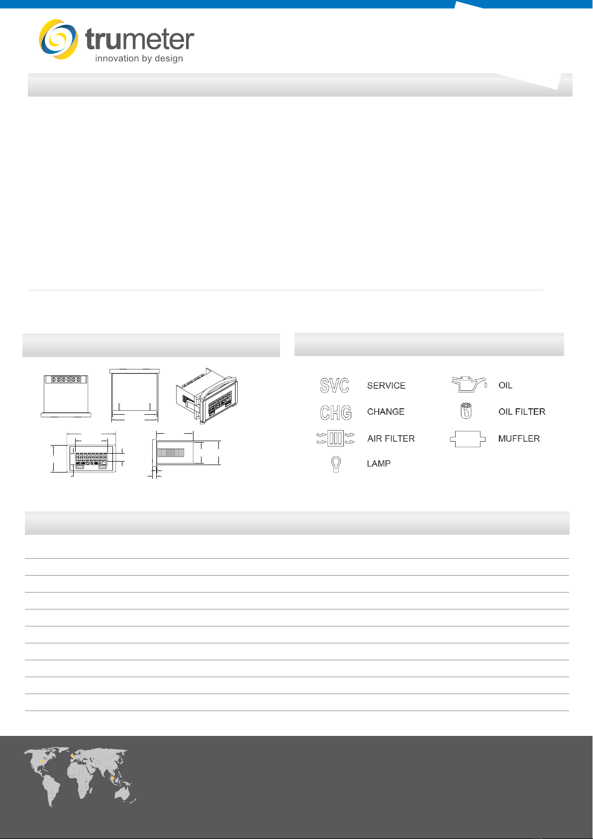
Optional Alert Functions
The Model 63 Counter can be programmed to operate as a
maintenance device in which alerts notify the user of certain
maintenance actions to be taken after accumulation of a
predefined number of counts. When the accumulated count
equals the predefined alert value, an icon is illuminated on the
display. When the alert is reset, the icon is turned off, but the
count value is not reset.
There are two types of alerts. The first is a break-in alert. A
break-in alert only occurs once at the start of unit operation.
The second type of alert is recurring. A recurring alert occurs
continuously at a predefined period. When tied to a break-in
alert, the recurring alert will not begin its count until the break-in
alert has occurred.
The intervals for the recurring alert can be performed as start-to
start or end-to-start. A start-to-start interval count starts when
the last alert is turned on. The end-to-start interval count starts
when the last alert is turned off.
The Model 63 Counter can support three alerts using front panel
programming and four alerts when factory programmed. IT IS
NOT RECOMMEDED THAT THE PRESET FUNCTION BE
USED AT THE SAME TIME THAT ALERTS ARE ENABLED.
In both cases, Alert #1 is a break-in alert that is tied to Alert #2,
which is recurring. Alert #3 is recurring, and Alert #4 can be
factory set as either break-in or recurring. If Alert #4 is break-in,
then it is tied to Alert #3.
The Model 63 Counter can be programmed to be latched or kept
on for a predetermined number of counts. When latched, an
external reset is required to turn off the alert.
Front Panel
The liquid crystal display is reflective with dark characters on a
light background. There are 8 digits on the display. The standard
display contains seven icons which can be assigned as desired
to either alerts or a preset.
Model 63 Counters with the front panel programming option
are capable of being programmed for either alerts or the
preset function. There are two front panel switches. To begin
programming, the two switches are pressed simultaneously. The
programming menu must be completed in its entirety to return to
normal operation. The switch functions are described as follows:
SEL: During normal operation, the displayed
counters will be swapped when the SEL switch is
pressed and released. During programming, this
switch is used to select options.
RST: During normal operation, the RST switch is
used for front panel reset. During programming, the
RST switch is used to enter an option.
Resets
Unless using alerts, a reset returns the display to zero. If using
alerts, the reset turns an alert off. There are three different reset
configurations available:
Non-Reset: The counter can never be reset. A non-reset unit
also has no front panel programming option.
Remote Reset: A model with Remote reset has a dedicated
terminal for performing the reset function. The unit resets when
the remote reset signal is at a high level. When the reset signal is
at a low level, accumulating counts can occur.
Manual Reset: Manual reset occurs when the RST switch on the
front of the counter is pressed. Counting resumes upon release
of the RST switch. The exception to this operation is in the Dual
Counter case in which the non-resettable counter cannot be
reset.
Note: Some counters are equipped with a Manual Reset
Enable Input. In this case, the Manual Reset Enable Input
must be high for the RST switch to be functional.
Operations
Part Numbers
www.trumeter.com
Trumeter (Europe)
Pilot Mill
Alfred Street
Bury,
BL9 9EF
Tel: +44 161 674 0960
Email: sales.uk@trumeter.com
Trumeter (The Americas)
6601 Lyons Rd, Suite H-7,
Coconut Creek, Florida
FL 33073,
USA
Tel: +1 954 725 6699
Email: sales.usa@trumeter.com
Innovative Design Technologies Sdn. Bhd
Lot 5881, Lorong Iks Bukit Minyak 1
Taman Perindustrian Iks, 14000 Bukit Tengah
Penang, Malaysia
Web: www.idtworld.com
Tel: + 604 5015700
Email: [email protected]
6300-DS.v.3.1 02/2021
Specications
Display Figures: 8 LCD digits 0.32” [8mm] high
Annunciators Icon: A choice of 7 Icons 0.08” [2mm] high
Reset: Remote, manual & non-reset. Manual reset enable is
available on some models
Speed: Low speed: 0-40 counts per second (min. 12.5ms-on, 12.5ms-
o󰀨)
High speed: 0-500 counts per second (min. 1.0 ms-on, 1.0
ms-o󰀨)
Inputs Switch (no voltage)
DC Voltage:
Absolute voltage range: -0.5 VDC, minimum to
30.0VDC, maximum
VIH: 3.0 VDC, maximum
VIL: 1.0 VDC, minimum
High Voltage AC/DC:
Absolute Maximum voltage: 300VAC/VDC
VIH: 10VDC/20 VAC, max.
VIL: 3VDC/3 VAC, minimum
Power: Internally powered models: Self powered
Battery Life: 10 years
Mounting: Panel with clip
Terminations: Terminal block
Weight: 2 oz. [57g]
Environmental: Temp. (Storage & Operating): -4˚F to +140˚F
[-20˚C to +60˚C]
Humidity: 0 to 95% RH, non-condensing
Vibration: Operating: 10 to 55 Hz, 0.01” [0.25mm] double
amplitude
Non-operating: 10 to 55 Hz, 0.03” [0.75mm] double amplitude
Shock: Operating: 10G’s
Non-operating: 30G’s
Dielectric: 1000 VAC 50/60Hz for 1 minute
Accuracy: 100% (provided signal meets stated parameters)
EMC Compliance: EN61326:1997 with A1: 1998 & A2:2001 for industrial
environments
Enclosure: NEMA 4/4X, 12, & IP66 compliance (from the front)
when properly mounted using the optional gasket
Approvals: CE compliant, UL & cUL recognized
Environmental Compliant to the European WEEE & RoHS
Compliance:
Dimensions
Notes
1. When interfacing the Model 63 with a Solid State Relay or AC Sensor, the leakage current needs to be considered.
2. The Absolute Voltage Range and the Absolute Maximum Voltage are the voltages at which operation beyond the specied limits may result in damage to the unit.
Part Number Description Gasket
6300-0000-0000 DUAL RANGE COUNTER 40/500HZ DRY CONTACT INPUT REMOTE RESET 5003-013
6300-0500-0000 DUAL RANGE COUNTER 40/500HZ DRY CONTACT INPUT PROGRAMMING/FPRESET inc REDI-ALERTS 5003-013
6300-0600-0000 DUAL RANGE COUNTER 40/500HZ DRY CONTACT INPUT FPRESET **SPECIAL ORDER** MOQ = 50 PCS 5003-013
6300-1000-0000 DUAL RANGE COUNTER 40/500HZ 3-30 VDC INPUT REMOTE RESET 5003-013
6300-1500-0000 DUAL RANGE COUNTER 40/500HZ 3-30 VDC INPUT PROGRAMMING/FPRESET inc REDI-ALERTS 5003-013
6300-1600-0000 DUAL RANGE COUNTER 40/500HZ 3-30 VDC INPUT FPRESET **SPECIAL ORDER** MOQ = 50 PCS 5003-013
6300-2500-0000 DUAL RANGE COUNTER 40/500HZ 10-300/20-300 VDC/VAC INPUT PROGRAMMING/FPRESET inc REDI-ALERTS 5003-013
6300-2600-0000 DUAL RANGE COUNTER 40/500HZ 10-300/20-300 VDC/VAC INPUT FPRESET **SPECIAL ORDER ** MOQ = 50 PCS 5003-013
6301-2000-0000 COUNTER 40HZ - 10-300/20-300 VDC/VAC INPUT REMOTE RESET 5003-013
FOR FRONT PANEL PROGRAMMABLE PRESET AND REDI-ALERT OPTIONS PLEASE CONTACT US.
2.00 [50.8]
1.86 [47.3]
.16 [4.0]
.02 [0.5]
1.76 [44.7]
1.50 [38.0]
.31 [8.0]
1.10 [27.9]
.87 [22.1]
.48 [12.1]
1.31 [33.4]
.97 [24.7]
Panel Cutout: 1.79” [45.5mm] x 0.89” [22.6mm]
Recommended Panel Thickness: 0.125” [3.1mm]
Available Icons

Other Trumeter Cash Counter manuals

Trumeter MULTICOUNT User manual

Trumeter

Trumeter MULTICOUNT User manual

Trumeter EMP-9100 User manual

Trumeter

Trumeter EMP-9100 User manual

Trumeter 7010 User manual

Trumeter

Trumeter 7010 User manual

Trumeter FALCON HED251-R User manual

Trumeter

Trumeter FALCON HED251-R User manual

Trumeter 9100 User manual

Trumeter

Trumeter 9100 User manual

Trumeter 7911 User manual

Trumeter

Trumeter 7911 User manual

Trumeter 7931 User manual

Trumeter

Trumeter 7931 User manual

Trumeter 898 Series User manual

Trumeter

Trumeter 898 Series User manual

Trumeter Durant E4148793 User manual

Trumeter

Trumeter Durant E4148793 User manual

Trumeter 898X User manual

Trumeter

Trumeter 898X User manual

Trumeter 7922 User manual

Trumeter

Trumeter 7922 User manual

Trumeter 34 Series User manual

Trumeter

Trumeter 34 Series User manual

Popular Cash Counter manuals by other brands

socomec COUNTIS ATd operating instructions

socomec

socomec COUNTIS ATd operating instructions

Thermo Scientific Invitrogen Countess 3 user guide

Thermo Scientific

Thermo Scientific Invitrogen Countess 3 user guide

MA NC-6000 Service manual

MA

MA NC-6000 Service manual

Carrier EVERGREEN 23XRV Application guide

Carrier

Carrier EVERGREEN 23XRV Application guide

Agilent Technologies 53151A operating guide

Agilent Technologies

Agilent Technologies 53151A operating guide

HYOSUNG MX-4000W Operator's manual

HYOSUNG

HYOSUNG MX-4000W Operator's manual

Kübler 560 manual

Kübler

Kübler 560 manual

HDI 2100 user manual

HDI

HDI 2100 user manual

BEKA BA567E-SS manual

BEKA

BEKA BA567E-SS manual

DIEBOLD NIXDORF DN 490 Operator's manual

DIEBOLD NIXDORF

DIEBOLD NIXDORF DN 490 Operator's manual

Motrona ZX020 operating manual

Motrona

Motrona ZX020 operating manual

Kayoba 003236 operating instructions

Kayoba

Kayoba 003236 operating instructions

Note&coiN NCS2010P user guide

Note&coiN

Note&coiN NCS2010P user guide

DoCash 3040 Series user manual

DoCash

DoCash 3040 Series user manual

Precision Digital Corporation PROVU Series quick start guide

Precision Digital Corporation

Precision Digital Corporation PROVU Series quick start guide

Labelmate Count-100 user manual

Labelmate

Labelmate Count-100 user manual

HP 5315 A Operating and service manual

HP

HP 5315 A Operating and service manual

VAKI Micro user manual

VAKI

VAKI Micro user manual

manuals.online logo
manuals.online logoBrands
  • About & Mission
  • Contact us
  • Privacy Policy
  • Terms and Conditions

Copyright 2025 Manuals.Online. All Rights Reserved.