Eurotech EUROLAM User manual

Roll to Roll laminator
UserManual
Free Call 1800 30 6161 | info@eurotech.com.au

The Package is made of Steel buckle box and Plywood
board, free of Fumigation.
The package dimensions:
225cm!76cm!81cm
The box shall be disassembled by loosening the buckles around the
edges. !
Tools Needed: HammerFlat"Tip"Screwdrivers!
PACKING INSTRUCTION
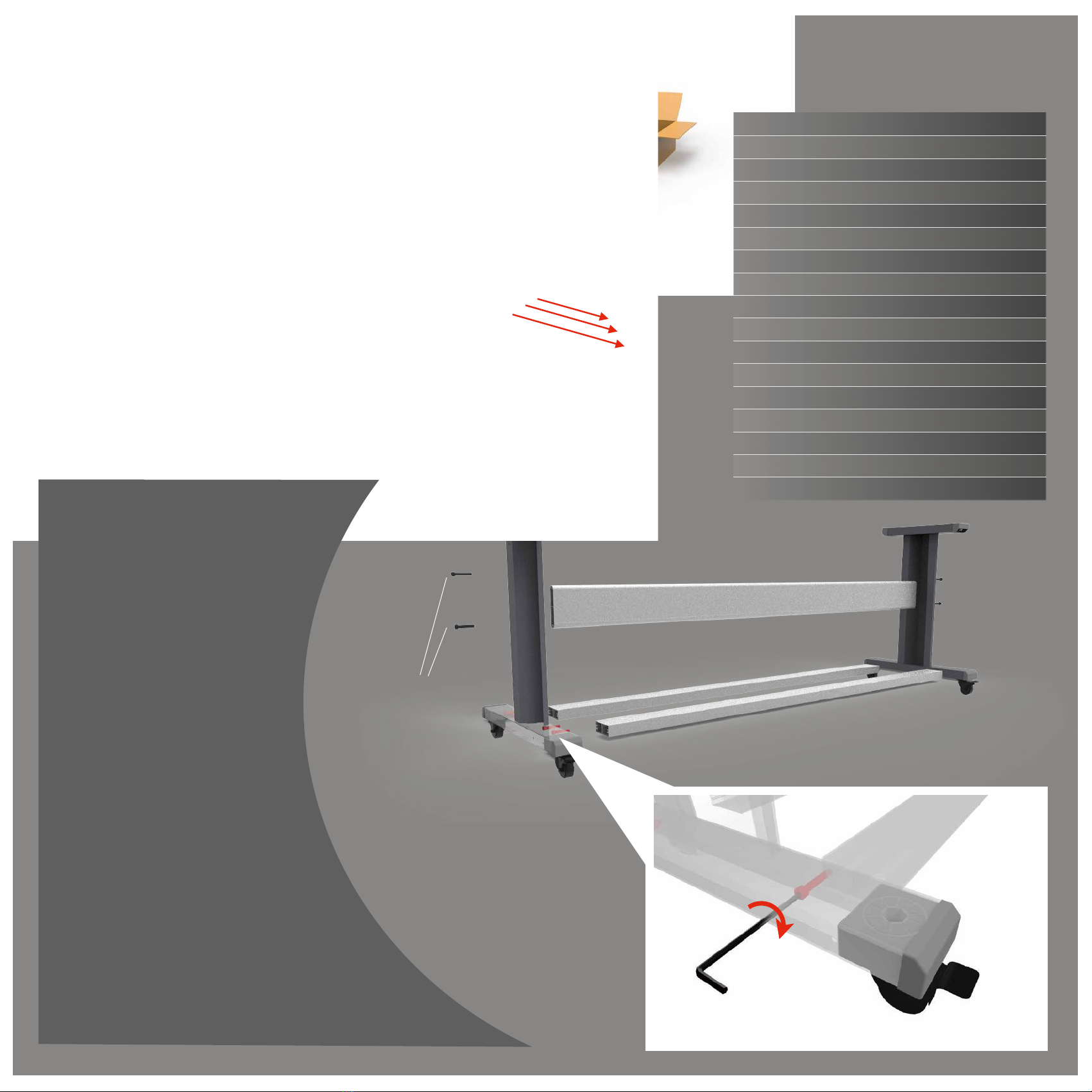
Release Main machine from the package bottom:
1. Cut off the belt fixing the Main Machine, and release it out of the package.
2. Cut off the belt fixing the Stand connection beams at the bottom, and pull the beams out and put aside.
3. Remove all the walls of case.
225cm
76cm
81cm
Stand with feet wheels
Stand connection Beams
Fixed on the front part of the
wooden case by two bolts. We
need remove the bolts first to
release the stands.
Fixed on the package bottom, bind by the fasten belt. Air compressor
Packed together with Main machine, fixed by belt
from the bottom, we need cut off the belt to release
the air compressor from the bottom. Then take the
compressor out.
Heating Elements
Packed inside of PVC tubes, fixing by the blue
packing film. The machine just install one unit, the
other one is for standby.
Power Cable
Fixing by the blue packing film.
ACCESSORY BOX CONTAINS:
Bolts
M-8!16mm
Stand Frame Assembly:
Assembling the stand frame is
the first step to built your
laminator.
Both of the Stand frames are
totally the same, which could
be assembled at will.
Take out the bolts M-8×16mm,
and put the stands frame and
the stand beam together, then
screw the bolts into the thread
hole.
Note: PLEASE FASTEN THE BOLTS
THROUGH THE HOLES AT OUTSIDE OF
STANDS WHEN INSTALLING. Just like the
close-up shot showing.
HEXAGONSOCKET BOLTS M-8×16 mm 12 pieces
Round Shim !8×1.5mm 4 pieces
Open end wrench 8mm 2 pieces
Nuts M8 4 pieces
Inner hexagon wrench No.3/4/5/6 1 piece/each
Bolts Gasket 3.5cm×6cm 4pieces
Fuse/15A 1 piece
Fuse/1A 1 piece
Oil-water Separator with fixing screws 1 piece
Feet Pedal 1 piece
Big Fraction Pad 2 Pieces
Small Fraction Pad 2 Pieces
Air Tube 5×8mm 3 m
U-shape Shell(Standby) 2 Pieces
Tension Knob 2 pieces
Slitting head 1 piece
Power Cable 1 piece

INSTALL THE MAIN MACHINE
We need four person to raise the main machine up
from the package bottom. Take care for the holding
position, better on the main frame/table. Just like
the yellow points showed:
Note to align the four fitting holes on top of
stands when dropping.
Then screw the nuts back to fixing the
machine fitting.
Fixing Nut

DIAGRAM OF WHOLE MACHINE
• Prints Loading Shaft
• Liner Collecting Shaft
• Upper Roller
• Lower Roller
• Control Panel
• Handle Valve
• Take-up Rod
• Water-Oil Separator
• Tension Knobs
• Finishes Collecting Shaft
• Film Loading Shaft
• Feet Pedal Connector
• Overhaul Window
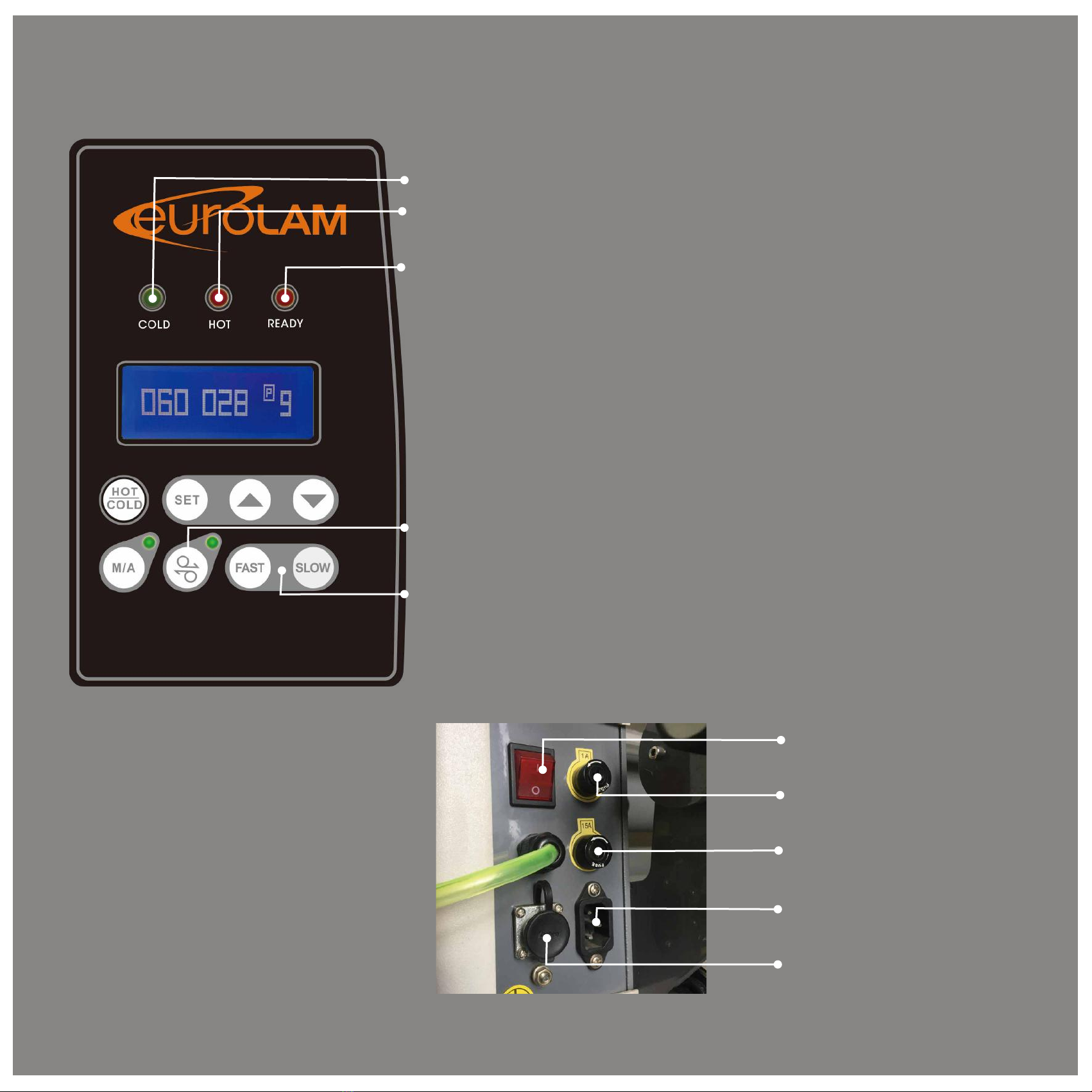
INSTRUCTION OF CONTROL PANEL/BACK PANEL
!Hot light:
"lighting means the machine roller working under hot state
!Cold light:
"lighting means the machine roller working under cold state
!Ready light:
"lighting means the roller surface temperature has reached the
set value
!Hot/cold switch:
"Control the switch of hot/cold model
!M/A switch:
"under Auto model, the machine can keep running at the speed
set;
"under Manual model, the machine is controlled by the feet
pedal.
!Forward/backward switch:
"Control the direction the roller running, usually used during film
installing.
!Speed adjust button:
"Just adjust the working speed
#About setting:
3UHVVWKH6HWEXWWRQIRUƉUVWWLPHZH
ZLOOHQWHUWKHWHPSHUDWXUHVHWWLQJ
HQYLURQPHQWKHUHZHFDQVHWWKH
WHPSHUDWXUHRIODPLQDWLQJ
3UHVVWKH6HWEXWWRQIRUVHFRQGWLPH
ZHZLOOJRWWKHLQWHUIDFHRILQSXWWLQJWKH
FRGHWKLVLVE\RXUIDFWRU\LJQRUHLW
SOHDVH
3UHVVWKH6HWEXWWRQIRUWKLUGWLPHWR
HQGXS\RXUVHWWLQJ
!3RZHU6ZLWFK
!!"#$%&'%()*%
!!"#$%&+'%()*%
!3RZHU&DEOH
&RQQHFWRU%

3RZHU6XSSO\
,-$%.)//$.01)/%#).2$0#%-34$%0)%($%.5)#$%0)%0-$%63.-1/$7%%
8 '9%4)503:$%;<<%=%>%;?<%=%%
8 @A$B"$/.CD%+<%E%F<%GH%%
8 #0A$/:0-%)@%$5$.0A1.%."AA$/0D%I'%%
/RFDWLRQ%
,-$%5).301)/%0)%J53.$%0-$%63.-1/$%6"#0%JA)41K$%$/)":-%#J3.$%0)%L)A27%M)/N0%@)A:$0%0-30%#J3.$%1#%35#)%/$$K$K%0)%
1/#$A0%3/K%A$6)4$%0-$%630$A1357%O5$3#$%.)/#1K$A%0-$%K16$/#1)/#%)@%0-$%J1.0"A$#%3/K%#-$$0#%"#$K7%%
%
3ODFH%
OA$J3A$%3%P30%5).301)/%#"10$K%0)%0-$%#1H$%)@%0-$%63.-1/$%3/K%35#)%.)/#1K$A%10#%3..$##)A1$#7%%
%
/LJKWLQJ%
Q))K%51:-01/:%R?<<%E%F<<%5"*S%1#%1/K1#J$/#3(5$%0)%)J$A301/:%3/K%631/031/1/:%0-$%63.-1/$%#3@$5C7%%
%
5RRPSURSHUWLHV%
,-$%5361/30)A%-3#%0)%($%J53.$K%1/%3%.5)#$K%A))6%3/K%-3#%0)%($%JA)0$.0$K%3:31/#0%L$30-$A%$T$.07%%
8 O$A61##1(5$%A))6%0$6J$A30"A$D%&IU9%0)%?+U97%%
8 G"61K10C%A3/:$%J$A6100$KD%?<V%0)%I<V%%
%
(OHFWULFLW\FRQQHFWLRQ%
9-$.2%0-30%0-$%$5$.0A1.35%#"JJ5C%.)AA$#J)/K#%L10-%0-$%63.-1/$%J$A@)A63/.$7%%
W10-%.)//$.01/:%0)%0-$%$5$.0A1.10C%#"JJ5CX%0-$%5361/30)A%6"#0%($%$3A0-$K7%%
,)%.)//$.0%0-$%5361/30)A%L10-%$5$.0A1.%#"JJ5C%#C#0$6D%%
8 Y/0$AA"J0%0-$%."AA$/0%#"JJ5C7%%
8 9)//$.0%0-$%.)//$.01)/%.3(5$%0)%3%#"103(5$%J5":%)A%K1A$.05C%0)%0-$%631/%R.3J#"5$%A315X%Z"/.01)/()*X%$0.7S7%%
Further advises for installation:

•Take out the air compressor from the package, install four units of
rubber feet.
•Take off the white PVC plug on the cooling fin block, twist the black
filter into the hole, then plug the blue tube into the hole at the bottom
of the filter.
•Take out the air tube from the accessary box, then plug one end into
the interface on the compressor, the other end into the interface on
the water-oil separator on the machine leg.
•Plug the power cord into the socket.
"Air compressor connection finished!
CONNECT THE AIR COMPRESSOR

Start Using Air compressor
- Ensure the red hand valve is staying at the position showed.
90°
- Ensure the Red button on the top of the air compressor staying pressed
-Then we plug in the power for Air compressor
- Pull the Red button to start the Air compressor to compress the air.
- 1~2 minutes later, the air compressor will stop automatically once the pressure
reach around 0.8Mpa.
- Twist the Red handle valve to the position shown, and the air pressure will be directed to
to the Eurolam.
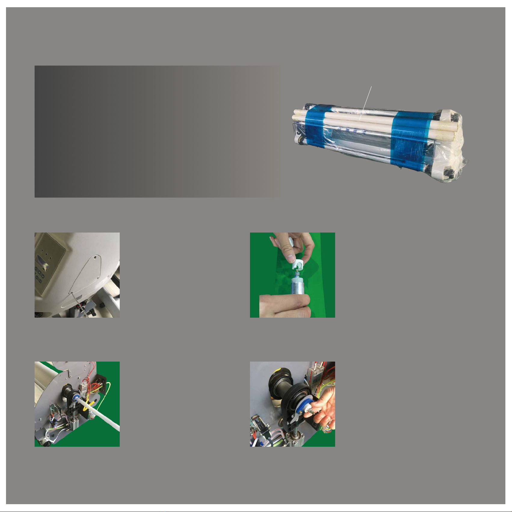
Heating Elements installation
The Eurolam can work normally without the heating element, it will
just lack the heating function.
The heating element is extremely fragile. We recommend two
people during the installation, in order to assure proper handling.
Take the heating element out of the white PVC tube, ensuring it
doesn't knock on other items. Again - it is very fragile.
Heating Elements
Remove the bolts in the Overhaul
Window with the hex key
supplied in the accessory box.
Step 1 Step 2
Step 3
Plug the heating tube into the
center of the up roller, just like
the picture shown, straight
through the roller.
Remove the white ceraming part on
the end of the heating tube, then
release the white ceramic cover by
twisting it, then take off the ceramic
part from the end together, just like
the picture shows.
Step 4
After you plugged in the
heating element, it should
look like the picture shown.
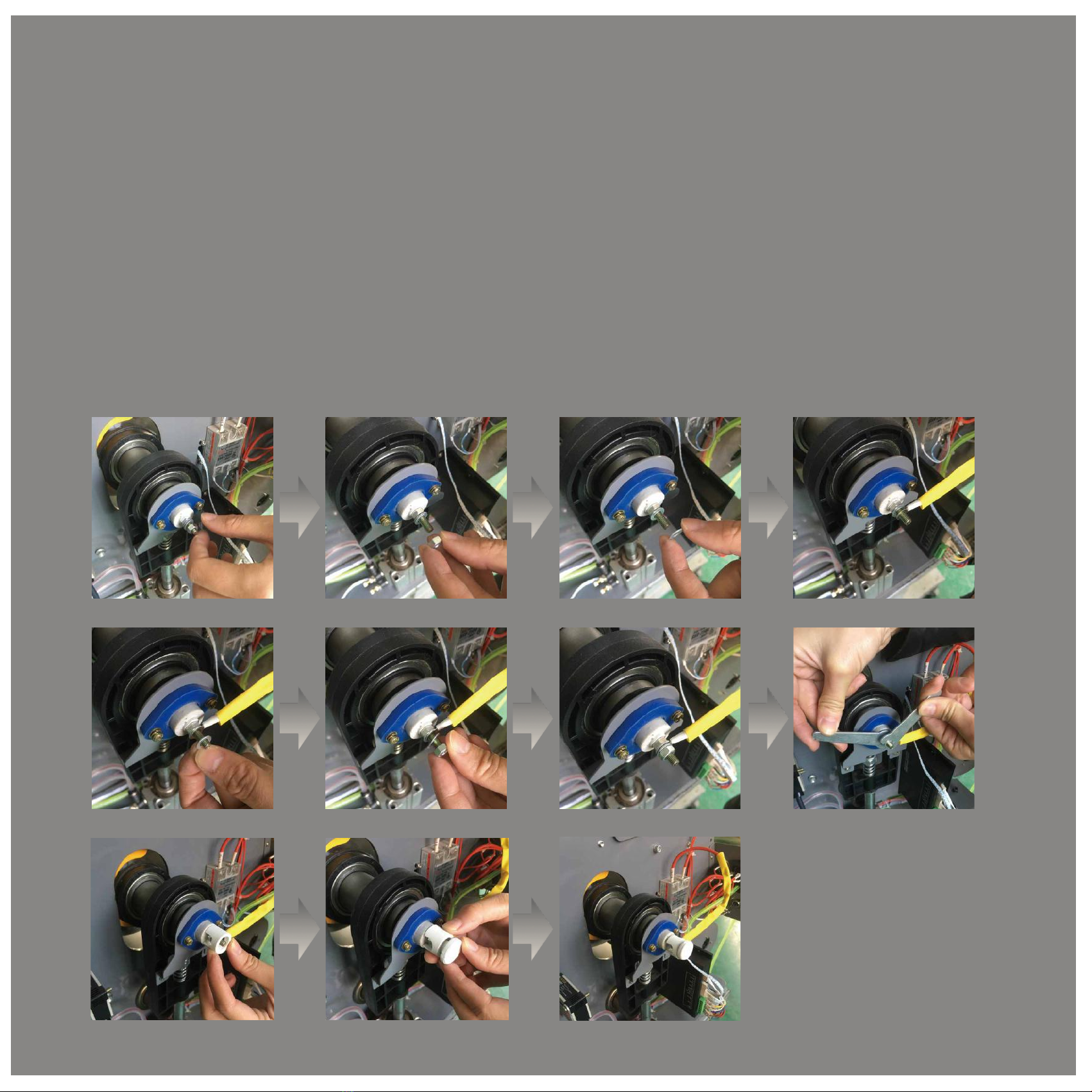
Use the open-ended wrench to unscrew the outer cover of the heating tube and remove its flat gasket. Connect the end of the
red heating wire with the screw of the heating element (marked 'hot A'), as shown in the picture.Put the flat gasket back in
place, then press the wire terminal to the gasket and twist the outer screw back in place. Use an open-end wrench to tighten
the outer screw and inner screw in opposite directions.
Put the ceramic part back onto the heating tube screw, then twist back the the white ceramic cover.
Then same operation in the other end of the heating tube.
Then screw the cover back on.
Step 5
Heating element installation finished!
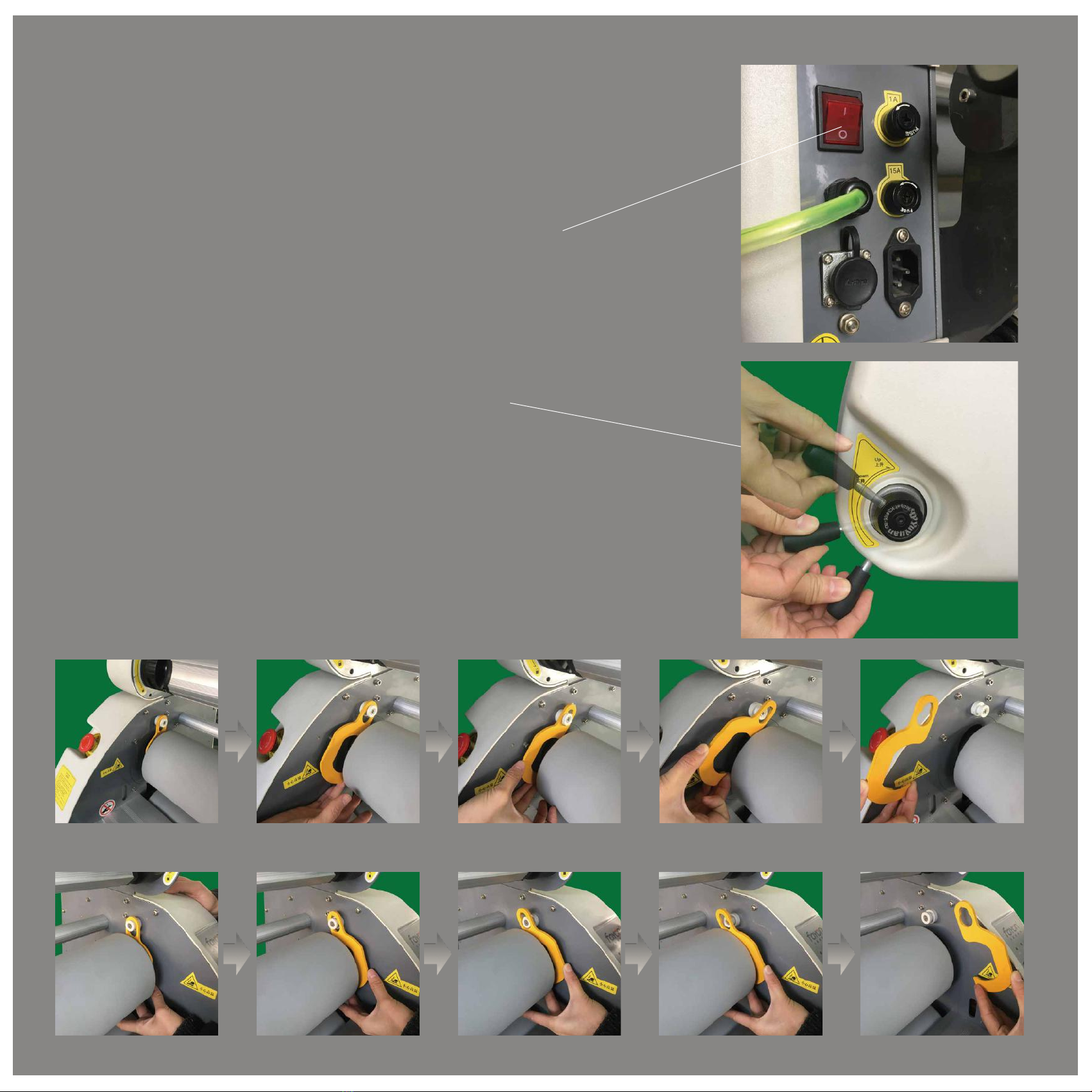
Start Using the EuroLam
Power on the laminator
Push the rocker switch on the back of the machine case, from ‘0’ to
‘I’. The control panel screen will light up, showing the greeting
words: Welcome.
If the screen fails to light up, please check if any emergency stop
is activated. Just twist the button clockwise to release it. Then the
screen should light up.
Turn the Pneumatic valve to ‘up’ position, the upper roller will lift up
Take off the upper roller hanging hooks
Take off the yellow upper roller hanging hooks on double sides,
this parts designed to protect the rollers in long-term transport by
keep the upper and lower rolls from moving.
The hooks also avoid roller deformation that occurs when the
machine is idle for long periods of time
Up
Down
Middle
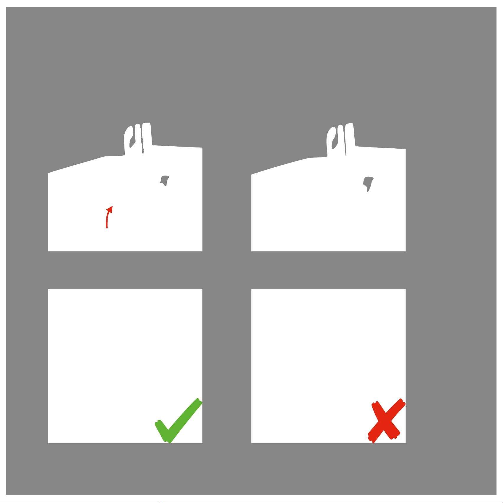
$The use of the bracket
Turn the black holding bracket shell as indicated by the arrow, twist the bracket until you got a click, it is now open.
Then pull out the media shaft from the slot.
Attention: Ensure the peg of the media shaft connects parallel to the opening of the EuroLam.
Closed Opened
After putting the media rod back in the bracket, please turn the bracket shell back to lock the shaft. This step is
important!

Working schematic diagram
film rolling outside
film
back paper
film outside rolls
back paper
film
film inside rolls
film rolling inside
Accordingly, there are two types of film installing as below, please take more attention on the running
direction:
1. 2.
1. 2.
There are two ways to roll film in the market:
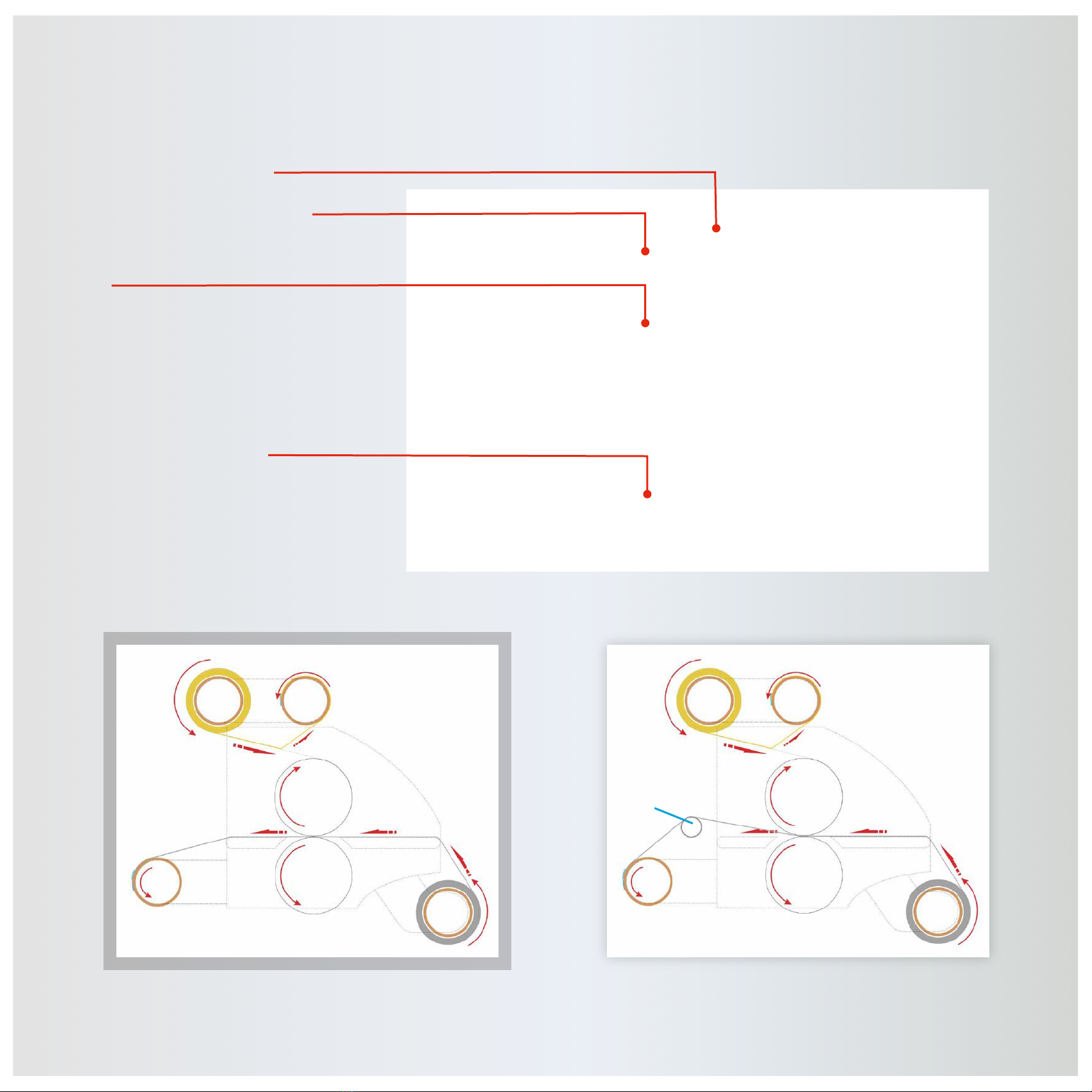
Working Diagram
Film Loading Position
Film-liner Collecting Position
Film
Prints Loading Position
Working Diagram without Slitting Working Diagram with Slitting
Film Liner
Upper
Roller
Finish Lower
Roller
Prints
Film Liner
Upper
Roller
Finish Lower
Roller
Prints
Slitting
Supporting
Bar
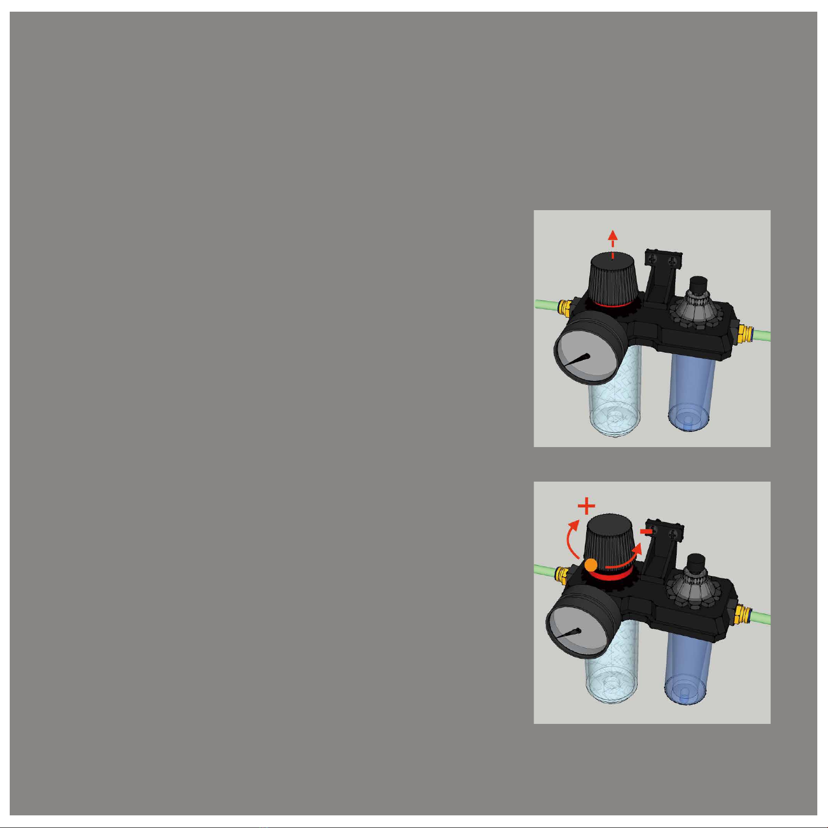
How to adjust the general pressure?
The default air pressure value is 0.4 Mpa;
You can adjust the pressure value according to your needs.
1.
Increasing the air pressure
Pull the black knob, which will cause a slight unlocking sound. Then
rotate the knob clockwise, and you'll start to set an increase of the air
pressure gauge. After adjusting, push the black knob down to lock it,
which will in turn cause a slight locking sound.
2.
Reduce the air pressure
Pull the black knob, which will cause a slight unlocking
sound. Then rotate the knob anti-clockwise, and you'll start
to set an increase of the air pressure gauge. After adjusting,
push the black knob down to lock it, which will in turn cause
a slight locking sound.

When using the oil-water separator for the first time, please remember to add liquid
lubrication oil into the reservoir. Like the pictures below:
Regularly adding lubrication oil could improve the stability of the air cylinder and
lengthen its life.
Regularly clean the roller with cold water or ethyl alcohol. DO NOT use cold water when the
roller is hot, or it may cause damage.
Avoid using hard and sharp objects.
Use the yellow hanging hooks when the machine is idle for long periods of time in order to
avoid deformation.
After using the EuroLam for some time, the water collection bottle will be full. Please push
the outlet at the bottom of the bottle to drain the water out, which will cause a loud airflow
sound. It is normal and safe.
Routine maintenance for the EuroLam

Troubleshooting
If the screen is not lighting up when you turn on the machine:
Check that the emergency stop button is not activated. Please twist it clockwise
to unlock it.
If the roller is not heating after you pushed the Heat button and the light turned on:
Please make sure the heating element is installed properly.
If you have turned the valve down but the roller hasn't moved:
Check if the yellow hanging hooks are still on.
If you have turned the valve up but the rolled hasn't moved:
Please recheck if the air compressor's installation and connection was done properly.
The EuroLam stop working, while the Auto function is on:
Please check if any object or media is blocking the infrared safety device.

WARRANTY
CONTACT
Free Call 1800 30 6161 |info@eurotech.com.au
All our products are manufactured to the highest quality standards.
Our warranties are far from being complicated or difficult to handle - they provide
you with complete peace of mind with that in mind, the EuroLam is covered for a
full 3 years.
Table of contents


