Switch On
If the Controller is new and has not previously
been configured it will start up showing the ‘Quick
Start’ codes. This is a built in tool which enables
you to configure the input type and range, the
output functions and alarms.
!Incorrect configuration can result in
damage to the process and/or personal injury
and must be carried out by a competent person
authorised to do so. It is the responsibility of
the person commissioning the instrument to
ensure the configuration is correct.
To Configure Parameters in Quick
Start Mode
With ‘QckStart’ selected, press to scroll
through a list of parameters.
Edit the parameters using Vor .
When the required choice is selected a brief blink
of the display indicates that it has been accepted .
The first parameter is ‘Units’.
This parameter is associated
with Loop 1 ‘LP1’ and resides
in the ‘PV Input’ list as shown.
Continue setting up the paras presented until the
‘Finished’ view is displayed.
If all parameters are set up as required press V
or to select ‘Yes’.
The loop(s) are set to Auto on exit from Quick
Start and the controller re-starts in operator level
2.
The ‘HOME’ display is shown - see ‘Normal
Operation’.
☺If you wish to edit parameters again do not
select ‘Yes’ but continue to press .
All available parameters are shown in the following
tables.
Quick Start Parameters - Fixed Build Parameters shown in bold are defaults.
Group Parameter Value Availability
LP1
PV Input
Units
Engineering units for the PV. (C, F, K
options change the displayed units)
C, F, K
V. mV, A, mA, pH, mmHg, psi, Bar, mBar, %RH, %, mmWG, inWG, inWW, Ohms,
PSIG, %O2, PPM, %CO2, %CP, %/sec, Vacuum, sec, min, hrs, None
Always
LP1
PV Input
Resolution
Decimal point position for the PV
XXXXX, XXXX.X, XXX.XX, XX.XXX, X.XXXX Always
LP1
PV Input
Range Type
To select the linearisation algorithm
required and the input sensor.
Thermocouple: J, K, L, R, B, N, T, S, PL2, C, CustC1(2&3)
RTD: Pt100
Linear: 0-50mV, 0-5V, 1-5V, 0-10V, 2-10V, 0-20mA, 4-20mA
Always
LP1
PV Input
IO Type
Only shown if custom curve is selected
Thermocpl, RTD, Pyrometer, mV40, mV80, mA, Volts, HIZVolts, Log10
LP1
PV Input
Range High/Low
Max /min. display range and SP limits
Depends on Range type selected. Default 1372/-200 Always
LP1
Loop
Loop 1 Channel 1, control type (normally
Heat)
PID, VPU, VPB, Off,
OnOff
Always
LP1
Loop
Loop 2 Channel 2, control type (normally
Cool)
PID, VPU, VPB, Off,
OnOff
VPU = Boundless valve position control. This does not
need a feedback potentiometer
VPB = Bounded valve position control. Requires a
feedback potentiometer
Always
LP2
PV Input
Source
Defines where the PV input is wired to
None, FixedPV, Module6 (Module6 is available only if an analogue input module
is fitted).
If a dual loop
controller
The LP1 parameters listed above are repeated for LP2 if the LP2 PV Input is configured.
Logic function (input or output)
To configure the function of Logic IO which
can be an output or an input.
Not Used, Lp1 Ch1, Lp1 Ch2, Lp2 Ch1, Lp2 Ch2,
Alarm1 to 8, AnyAlarm, NewAlarm, ProgEvnt1 to 8,
LP1SBrkOP, LP2SBrkOP*, LPsSBrk*, (outputs)
LP1 A-M, LP1 SPsel, LP2 A-M, LP2 SPsel, AlarmAck,
ProgRun, ProgReset, ProgHold (Inputs)
[Note 1] [Note 2]
* LP2 and LPs (both loops) only shown if
the second loop is configured.
Programmer options only available if the
controller is a programmer/controller.
Init
LgcIO LA
Min OnTime (if configured as a control OP) Auto, or 0.01 to 150.00 [Note 2] [Note 3]
The above two parameters are repeated for the LB Logic I/O (LgcIO LB)
Init
RlyOP AA
AA Relay output
function
This relay is always fitted.
Not Used, Lp1 Ch1, Lp1 Ch2, Lp2 Ch1, Lp2 Ch2, Alarm 1 to 8, Any
Alarm, New Alarm, ProgEvnt1 to 8, LP1SBrkOP, LP2SBrkOP*, LPsSBrk*.
Always if the instrument Is ordered as a
programmer/controller. [Note 4]
Init
RlyOP AA
AA Relay Min OnTime Auto, or 0.01 to 150.00 [Note 2] [Note 3]
Note 1) Parameters only appear if the function has been turned on, eg If ‘Control Channel 1’ = ‘Off’, ‘Chan 1’ does not appear in this list. When a control
channel is configured for valve positioning, LgcIO LA and LgcIO LB act as a complementary pair. If, for example, Chan 1 is connected to LgcIO LA
(valve raise) then LgcIO LB is automatically set to Chan 1 (valve lower). This ensures the valve is never raised and lowered simultaneously.
The same complementary behaviour also applies to dual output modules and channels A and C of triple output modules
Note 2) If any input function, for example Chan 1, is connected to another input it will not appear in this list
Note 3) Is available if the Control Channel is not On/Off and is allocated to the LA, LB or AA output as applicable
Note 4) For valve position control Chan 1 or Chan 2 will not appear in this list. Valve position outputs can only be dual outputs such as LA and LB or dual
relay/triac output modules
To Re-enter Quick Start Mode
If you have exited from Quick Start mode (by selecting ‘Yes’ to the ‘Finished’ parameter) and you need to make further changes, the Quick start mode can be entered again at any time.
1. Hold down then power up the controller. Keep this button pressed until the ‘Startup’ - ‘Goto QckStart’ screen is displayed.
2. Press to enter the quick start list. You will then be asked to enter a passcode.
3. Use Vor Wto enter the passcode – default 4. If an incorrect code is entered the display reverts to the ‘Quick Start’ view.
It is then possible to repeat the quick configuration as described previously.
Note: The Quick Start view contains two additional parameters - ‘Cancel’ and ‘Config’.
Select Cancel to revert to normal operating mode.
Config will allow full configuration mode to be entered (after entering the correct pass code). Configuration is described in the Engineering Manual HA027988.
Quick Start Parameters -Alarms Parameters shown in Bold are defaults.
Group Parameter Value Availability
None No alarm type configured
Abs High/Low Absolute high/low
Init
Alarm 1 to 8
Type
Dev High/ Low/ Band
Deviation high/ low/ band
Always
None Not connected
PV Input Connected to main process variable does not appear if Alarm Type = Deviation
LP1/2 PV Connected to Loop 1/2 process variable
Init
Alarm 1 to 8
Source
Module1 - Module6 Connected to an analogue input module and only of the Alarm Type is not a deviation alarm
Always if Type ≠None
PV Input and ModX Ip do not
appear if Type = Deviation
Init
Alarm 1 to 8
Setpoint To adjust the alarm threshold within the range of the source. Always if Type ≠None
None No latching
Auto Automatic
latching
The alarm continues to be active until both the alarm condition is removed AND the alarm is
acknowledged. The acknowledgement can occur BEFORE the condition causing the alarm is removed.
Manual Manual latching The alarm continues to be active until both the alarm condition is removed AND the alarm is
acknowledged. The acknowledgement can only occur AFTER the condition causing the alarm is removed.
Init
Alarm 1 to 8
Latch
Event Alarm beacon does not light but any output associated with the event will activate and a scrolling message will appear.
Always if Type ≠None
No Continue back around the quick configuration listFinished Exit
Yes Go to normal operation. The loop(s) are set to Auto on exit from quickstart mode and the controller re-starts in Level 2.
Quick Start Parameters - Plug in I/O Modules
The controller automatically displays parameters applicable to the module fitted - if no module is fitted in a slot then it does not appear in the list.
Each module can have up to three inputs or outputs. These are shown as A, B or C after the module number and this corresponds to the terminal numbers on the back of the instrument. If the I/O is single only A
appears. If it is dual A and C appears if it is triple A, B and C appear.
Note: If an incorrect module is fitted the message ‘Bad Ident’ will be displayed.
Module type Parameter Value Availability
Change over relay (R4)
2 pin relay (R2)
Triac output (T2)
Dual Relay (RR)
Dual triac output (TT)
Relay (Triac) function
Not Used
All parameters the same as RlyOP AA, including Min OnTime if the OP is a relay
Always (if the module is fitted)
Single Logic Output (LO)
Triple Logic Output (TP)
Logic Out function Not Used
All parameters the same as RlyOP AA
Always (if the module is fitted)
Not Used Module fitted but not configured
LP1/2 Ch1/2OP Loop 1/2 Channel 1/2 control output
LP1/2 SP Tx Loop 1/2 setpoint retransmission
LP1/2 PV Tx Loop 1/2 PV retransmission
LP1/2 ErrTx Loop 1/2 error retransmission
DC Output function
LP1/2 PwrTx Loop 1/2 output retransmission
Range Type 0–5V, 1-5V, 1–10V, 2–10V, 0-20mA, 4-20mA
DC Output (D4)
DC Retransmission (D6)
Display High/low 100.0/0
Always (if the module is fitted).
Note: If a Dual DC Output module is fitted, it cannot be
configured using the Quick Start Code. To configure this module
refer to the Engineering Manual part no. HA027988.
Not Used Module fitted but not configured
LP1/2 A-M Loop 1/2 Auto/manual
LP1/2 SPsel Loop 1/2 SP select
LP1/2 AltSP Loop 1/2 Alternative SP select
AlarmAck Alarm acknowledge
Triple Logic Input (TL)
Triple Contact Input (TK)
Logic In function
ProgRun/Reset/Hold
Programmer run/reset/hold
A function can only be allocated to one input. eg if AlarmAck is
configured on X*A it is not offered for the other inputs
* is the module number.
LP2 does not appear if loop 2 is not configured.
Not Used Module fitted but not configured
LP1/2 AltSP Loop 1/2 alternative setpoint
LP1/2 OPH/L Loop 1/2 remote OP power max/min
Analogue IP function
LP1/2 V1/2Pos To read valve position from the feedback potentiometer loop 1/2
LP1/2 V1Pos and LP1/2 V2Pos only appear if Loop 1 or 2 and the
control channel 1 or 2 is set to VPB.
Alt/SP does not appear if the programmer option is supplied.
LP2 does not appear if loop 2 is not configured.
Range Type Thermocouple: J, K, L, R, B, N, T, S, PL2, C. RTD: Pt100
Linear: 0-50mV, 0-5V, 1-5V, 0-10V, 2-10V, 0-20mA, 4-20mA Not shown if analogue IP function not used
Analogue Input (AM)
Display High/low 100.0/0.0 These parameters only appear for Linear Range
Not Used Module fitted but not configured
LP1/2 AltSP Loop 1/2 Alternative setpoint
LP1/2 OPH/L Loop 1/2 output power maximum/ minimum
Potentiometer Input (VU) Pot Input function
LP1/2 V1/2Pos To read valve position from the feedback potentiometer loop 1/2
LP1/2 V1Pos and LP1/2 V2Pos only appear if Loop 1 or 2 and the
control channel 1 or 2 is set to VPB.
Alt/SP does not appear if the programmer option is supplied.
LP2 does not appear if loop 2 is not configured.
Transducer Power Supply (G3) TdcrPSU function 5 Volts or 10 Volts Always (if the module is fitted)
Transmitter power supply (MS) No parameters. Used to show the ID of the module if fitted
Normal Operation
Switch on the controller. Following a brief self-test sequence, the controller will start up
in AUTO mode and show the ‘HOME’ display in Operator Level 2 (following Quick Start).
If the controller is configured as a dual loop instrument the start up view shows a
summary of the two loops.
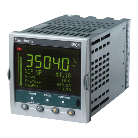
Note: Views shown in this guide are for 3504 and represent typical examples.
Beacons
OP1 Illuminates when output 1 is ON (normally heating)
OP2 Illuminates when output 2 is ON (normally cooling or alarm)
MAN Illuminates when manual mode active. If the HOME display is showing the dual loop overview, MAN
illuminates if Loop 1 is in manual. If the Loop 1 or Loop 2 overviews are being displayed MAN applies to the
loop being displayed.
REM Illuminates when alternative setpoint is active
SPX Illuminates when setpoint 2 is active
ALM If an alarm occurs the red alarm beacon flashes together with a message showing the source of the alarm,
for example ‘AnAlm1 - Abs Hi’ (the latter can also be a customised message). When acknowledged the
alarm message disappears. If the alarm condition is still present the beacon lights continuously. For non-
latched alarms it will extinguish when the alarm is cleared.
RUN Illuminates when the programmer running – flashing indicates End
HLD Illuminates when the programmer is in Hold (frozen)
J Flashes when J Channel digital communications is active
H Flashes when H Channel digital communications is active
IR On when infra red communications is enabled and flashes when infra red communications is active
Operator Buttons
A/MAN
This button
can be
disabled
Toggles the selected loop between Auto and Manual operation.
In Manual the controller output power is adjusted by the user using W
Vbuttons. The input sensor is still connected and reading the PV but
the control loop is open. ‘MAN’ will be indicated.
In Auto the controller automatically adjusts the output to maintain
control, ie the loop is closed.
The controller will power up in the mode it was in when it was powered
down.
PROG To select the programmer summary page
RUN/
HOLD
This button
can be
disabled
Press once to select a program. Press again to run the selected program.
‘RUN’ will be indicated in the top banner of the display.
Press again to hold a program. ‘HLD’ will be indicated
Press and hold for at least two seconds to reset a program.
‘RUN’ will flash at the end of a program
‘HLD’ will flash during holdback
+
‘ACK’. Press these buttons together to acknowledge an alarm.
Press to select new PAGE headings
Press to select a new parameter in the page
W
Press to decrease an analogue value, or to
change the state of a digital value.
V
Press to increase an analogue value, or to
change the state of a digital value
(Any parameter value can
be changed if it is
preceded by v)
Shortcut Key Presses
Backpage Press followed by c. With held down continue to press cor d
to scroll page headers backwards or forwards.
Backscroll When in a list of parameters, press 4followed by c.With 4held down
continue to press cor dto scroll parameters backwards or forwards.
Jump to HOME
display Press + 4
To Set The Required Temperature (Setpoint)
In the view above, press Wor Vto lower or raise the setpoint value of Loop 1.
The new setpoint is accepted when Wor Vis released and is indicated by a brief flash of the setpoint value.
To change Loop 2 setpoint, press . Loop 2 SP value is preceded by v. Press Wor Vas above to
change the value.
A momentary press of either button will show the setpoint in use, e.g. SP1.
Current access level Lev1; Lev2; or Lev3 (3504 only)
Press to scroll through further parameters
including programmer status details
Process Variable (PV) Loo
If the controller is configured as a
dual loop the HOME displays will
vary as shown here:-

