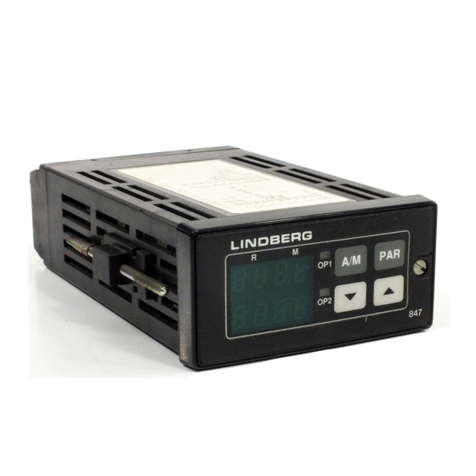
P304c Melt Pressure Controller
User Manual Part Number HA031861 Issue 3Date July 2014
Contents
1. DESCRIPTION......................................................................................................................................... 3
1.1 Unpacking Your Controller........................................................................................................................... 3
1.2 Dimensions..................................................................................................................................................... 3
1.3 Step 1: Installation........................................................................................................................................ 4
1.3.1 Panel Mounting the Controller ............................................................................................................................................4
1.3.2 Panel Cut Out Size .................................................................................................................................................................4
1.4 Order Code .................................................................................................................................................... 5
1.5 Step 2: Wiring ............................................................................................................................................... 6
1.5.1 Rear Terminal Connections ..................................................................................................................................................6
1.5.2 Block Diagram and Isolation Boundaries...........................................................................................................................6
1.5.3 Wire Sizes ................................................................................................................................................................................6
1.5.4 Power Supply..........................................................................................................................................................................7
1.5.5 Sensor Inputs ..........................................................................................................................................................................8
1.5.6 Transmitter Power Supply (TPSU).......................................................................................................................................9
1.5.7 Analogue Outputs................................................................................................................................................................10
1.5.8 Digital Inputs.........................................................................................................................................................................11
1.5.9 Alarms ....................................................................................................................................................................................12
1.5.10 Modbus Serial Communications..................................................................................................................................13
2. SAFETY AND EMC INFORMATION ...................................................................................................14
3. SWITCH ON ..........................................................................................................................................15
3.1 Operator Display ......................................................................................................................................... 15
3.1.1 Status Indication ...................................................................................................................................................................15
3.1.2 Keyboard ...............................................................................................................................................................................15
3.1.3 Example – To Display Selected Parameters ....................................................................................................................16
3.2 Open Indication ........................................................................................................................................... 16
3.3 Levels of Operation ..................................................................................................................................... 16
3.4 Level 1 Operation........................................................................................................................................ 17
3.4.1 Level 1 Parameters...............................................................................................................................................................17
3.4.2 Example 1 – To Set Alarm 1 Threshold.............................................................................................................................17
3.4.3 Example 2 – To Adjust the Output Level in Manual Mode ............................................................................................18
3.5 To Select Other Levels of Operation ......................................................................................................... 18
3.6 Level 2 Operation........................................................................................................................................ 19
3.6.1 Level 2 Parameters...............................................................................................................................................................19
3.7 To Return to Level 1 .................................................................................................................................... 21
3.8 Auto / Manual Mode ................................................................................................................................... 22
3.9 Alarms ........................................................................................................................................................... 23
3.10 Definition of Alarm Types ...................................................................................................................... 23
3.10.1 Process High....................................................................................................................................................................23
3.10.2 Process Low .....................................................................................................................................................................23
3.10.3 Band High ........................................................................................................................................................................24
3.10.4 Band Low..........................................................................................................................................................................24
3.10.5 Deviation High.................................................................................................................................................................25
3.10.6 Deviation Low..................................................................................................................................................................25
3.10.7 Alarm Mask at Start up...................................................................................................................................................26
3.10.8 Alarm Mask Reset ...........................................................................................................................................................26
3.10.9 Alarm Reset Mode ..........................................................................................................................................................26
3.10.10 Alarm Acknowledgement..............................................................................................................................................26
3.10.11 Failsafe mode ..................................................................................................................................................................26
3.10.12 Threshold .........................................................................................................................................................................26
3.10.13 Hysteresis .........................................................................................................................................................................26
3.10.14 Alarm Filter ......................................................................................................................................................................26
3.10.15 Behaviour of Alarms after a Power Cycle....................................................................................................................26
3.11 Pressure Transducer Calibration ........................................................................................................... 27
3.11.1 Calibration of a Pressure Transducer fitted with an internal shunt resistor...........................................................27
3.11.2 Calibration of pressure transducers with an external shunt resistor ......................................................................27
3.11.3 Calibration of an amplified pressure transducers with an internal shunt resistor................................................27
Part No HA031861 Issue 3July 14 CN31918 1

