EUROTRAS E PE Series Manual


www.eurotras.com
2
NORME DI SICUREZZA
•Prima di eseguire qualsiasi operazione di montaggio dei giunti, assicurarsi che le macchine da collegare
non possano in alcun modo mettersi in moto. È pertanto fatto obbligo accertarsi che l’alimentazione
elettrica sia disinserita.
•Le operazioni di montaggio devono essere eseguite esclusivamente da personale qualificato ed
appositamente addestrato.
•L’impiego di apparecchi di sollevamento per il posizionamento ed il montaggio dei giunti, richiede la
totale osservanza delle vigenti norme di sicurezza in materia.
•Ogni qualsiasi manomissione o modifica dei giunti dal suo stato originale sollevano automaticamente il
costruttore da eventuali danni diretti o indiretti cagionati a persone, animali o cose.
•In occasione del primo avviamento dell’impianto accertarsi che non si verifichino condizioni di pericolo
per le persone addette al montaggio. È indispensabile quindi mantenere una certa distanza di sicurezza
dal punto di installazione del giunto.
•I giunti, essendo parti rotanti, devono sottostare alle attuali normative comunitarie in materia
antinfortunistica, prevedendo l’utilizzo di appositi carter di protezione.
•Si ricorda, infine, che il giunto non deve mai superare i valori di coppia, di velocità e di disallineamento
angolare indicati dal costruttore.
INSTALLAZIONE
•Calettare i semigiunti sui rispettivi alberi bloccandoli con grani radiali o con rondelle di testa.
•Accostare i semigiunti tra loro montati di pioli in gomma e perni fino ad ottenere la quota H (tabella A).
•Verificare che l’inserimento di un semigiunto rispetto l’altro non comporti sforzo tra i pioli in gomma
e le rispettive sedi nel semigiunto opposto, questo significa che i semigiunti hanno già un buon
centraggio tra loro (altrimenti non potrebbero inserirsi uno con l’altro).
•Mediante strumenti di misura affinare l’allineamento dei semigiunti tra loro.
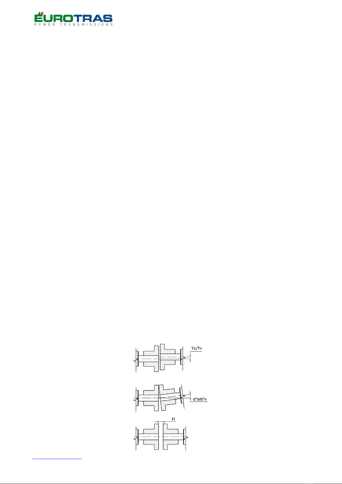
•Controllare che i disallineamenti ottenuti (figura 1) non superino mai i valori riportati nella
(tabella A). Si consiglia di ottenere valori di disallineamento vicini allo “0”
ϒo= Disallineamento parallelo orizzontale.
ϒv= Disallineamento parallelo verticale.
α°o= Disallineamento angolare orizzontale.
α°v= Disallineamento angolare verticale.
H= Spostamento assiale.
(figura 1)

www.eurotras.com
3
•Dopo le operazioni di cui sopra si devono eseguire alcuni avviamenti di prova per verificare se gli
allineamenti precedentemente eseguiti sono rimasti invariati.
•Dopo la messa in marcia dell’impianto è indispensabile effettuare le verifiche degli allineamenti dopo 100 ore
di funzionamento.
MANUTENZIONE
•Si consiglia di verificare, in funzione all’esercizio lo stato di usura dei pioli in gomma (ogni 500 ore di
funzionamento). Nel caso in cui si fosse verificata un’usura precoce si rende necessario verificare di non
aver superato i massimi valori consentiti di: Disallineamento angolare, Disallineamento radiale,
Spostamento assiale indicati nella (tabella A).
•In caso di usura degli elementi elastici o perni in acciaio si devono rimuovere gli anelli di arresto dal perno
in acciaio utilizzando una pinza speciale per l’apertura degli stessi al fine di rimuoverli dai rispettivi
semigiunti. Rimuovere successivamente gli elementi usurati e sostituirli con altri nuovi. I codici dei
ricambi sono presenti nella (tabella B).
STOCCAGGIO
•Lo stoccaggio dei semigiunti per lunghi periodi si deve eseguire proteggendo le parti lavorate, la
bulloneria, le rondelle e i pioli in gomma racchiudendo il tutto con film di polietilene.
www.eurotras.com
4
SAFETY RULES
•Before carrying out any joints assembly operation, make sure that the machines to be connected can’t in
any way start up. It’s therefore mandatory to make sure that the power supply is switched off.
•Assembly operations must only be carried out by qualified and specially trained personnel.
•The use of lifting devices for the positioning and assembly of joints requires full compliance with current
safety regulations.
•Any tampering or modification of the joints from its original state automatically relieves the manufacturer
from any direct or indirect damage caused to people, animals or objects.
•When starting the system for the first time, make sure that there are no dangerous conditions for the
persons in charge of the installation. It’s therefore essential to maintain a certain safety distance from the
joint installation point
•The joints, being rotating parts, must comply with the current Community regulations on accident
prevention, providing for the use of special protective casings.
•Finally, please remember that the joint must never exceed the torque, speed and angular misalignment
values indicated by the manufacturer.
INSTALATION
•Slide the half-couplings on the respective shafts locked with radial or head washers.
•accost half-couplings with each other mounted with rubber pins and pivots until to obtained H quote (table A).
•Verify that the insertion of one half-coupling with respect to the other does not cause stress between
the rubber pins and the respective seats in the opposite half-coupling, this means that the half-couplings
already have a good centering between them (otherwise they could not fit one with the other).
•By means of measuring instruments, refine the alignment of the half-couplings between them.
•Check that the misalignments obtained (figure 1) never exceed the values shown in (table A). It is advisable
to obtain misalignment values close to "0"
ϒo= Horizontal parallel misalignment.
ϒv= Vertical parallel misalignment.
α°o= Horizontal angular misalignment.
α°v= Vertical angular misalignmen.
H= Axial displacement
(figure 1)

www.eurotras.com
5
•After the above operations, some test starts must be performed to check if the previously performed
alignments have remained unchanged
•After commissioning the system, it is essential to check the alignments after 100 hours of operation
MAINTENANCE
•It’s recommended to check the wear of the rubber pins (every 500 operating hours) according to the
operation. In the event of premature wear, it is necessary to check that the maximum permitted
values of: Angular misalignment, Radial misalignment, Axial misalignment indicated in (Table A) have not
been exceeded.
•If the elastic elements or steel pins are worn, the retaining rings must be removed from the steel pin
using a special plier to open them in order to remove them from their respective half-couplings.
Remove the worn elements and replace them with new ones. The parts codes are present in (table B).
STORAGE
•Should half-couplings require long storage, the worked elements, the nuts and bolts, the washers and
the rubber pins shall be wrapped in a polyethylene film.
This manual suits for next models
60
Table of contents
Languages:


