Eurovacuum EV Series User manual

Eurovacuum
Installations and
Operating manual
EV Series
Vacuum pumps
Models 0010 - 0750
Single Stage Oil Sealed Rotary Vane Pump
Eurovacuum EV Series
Single Stage Oil Sealed Rotary Vane Pumps
Eurovacuum Company is offering its various products to meet industrial vacuum needs.
Eurovacuum Company is founded in 2006, with over 30 year experiences in the vacuum
Industry its founders have een putting there est efforts continuously to produce high quality
Oil Sealed Rotary Vane Pumps, with diverse range of capacity for use in printing, food
processing, packaging, plastic moulding, vacuum lifting, hospitals and la oratories or other
industrial application.
Application Examples
• Car industry
• Food industry
• Furnaces and plants
• Laser technology
• Medicinal technology
• Metallurgy
• Power engineering, long-distance energy
• Space simulation
• Vacuum coating
Advantages to the User
• High pumping speed also at low pressures
• Low noise level
• ntegrated exhaust filter, Discharge Air 99.9% Oil Free
• No oil loss owing to the integrated oil return line
• Air-cooling, no water required
• Low space requirement, easy to install
• Spin-on Oil Filter on all sizes from EV-0030
• Maintenance-friendly
• Compact design
• Anti-Suckback valve to secure the vacuum
in the system
• High water vapour tolerance
• Direct drive, Design requires no belts
• Wide range of accessories available for
easy adaptation
Eurovacuum Head office
Tel. +31-(0)854890993
Einsteinstraat 58 info@eurovacuum.eu
2811 E Reeuwijk http://www.eurovacuum.eu
The Netherlands
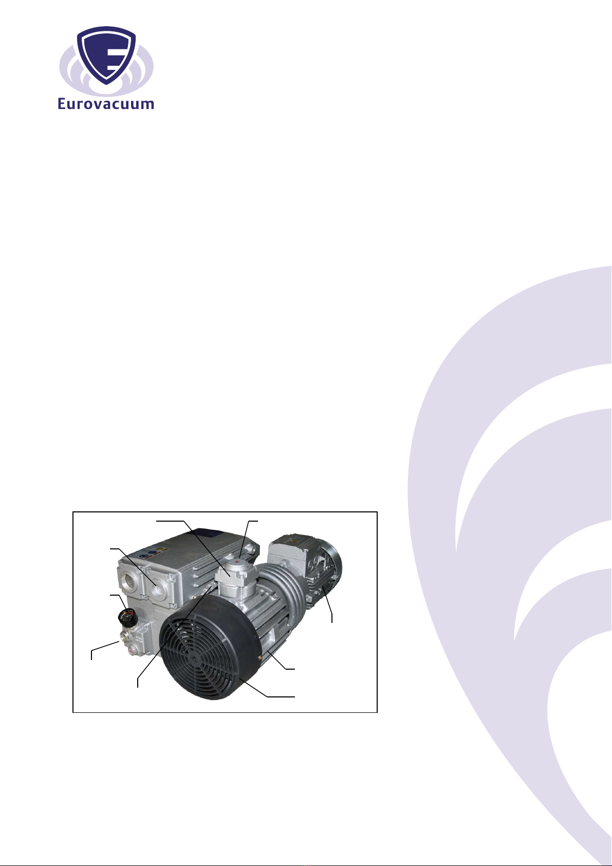
Anti-suckback valve Inlet flange with filter screen
Integrated
exhaust
filters
Exhaust
pressure
gauge
High efficiency
Motor
Oil level Low oise Level
sight glass
Gas ballast Valve Efficient Air Cooling

Contents
It is mandatory that these operating instructions be read and
understood prior to the vacuum pump installation and start-up.
1.0 INSTALLATION
1.1 Unpacking
1.2 Location
1.3 Power Requirements
1.4 Vacuum Connections
1.5 Oil Filling
2.0 SA ETY
2.1 General Notices
2.2 Warning Label and explanation
2.3 Location of Labels
3.0 OPERATION
3.1 Start-up
3.2 Stopping the pump
3.3 Gas Ballast
3.4 Check Valve (Built -in)
3.5 Exhaust Filter Pressure Gauge (optional)
4.0 MAINTENANCE
4.1 Pump Oil (level/type/quantity/change)
4.2 nline (inlet) Filter
4.3 Exhaust Filter
4.4 Gas ballast filter
4.5 Maintenance Chart
4.6 Gasket Kit, Overhaul Kit and other parts and accessories
5.0 PROBLEM SOLVING
6.0 TECHNICAL DATA
Version A3; March 2017

INSTALLATION AND OPERATING MANUAL
This manual is written to cover EV-Series Model vacuum pumps. The model number is stamped into
the nameplate. The number will appear as follows :
EV-xxxxL; EV-xxxxNM, EV-xxxxF, EV-xxxxG or EV-xxxxH
Please identify the model number and serial number when ordering parts.
Versions:
L: 20 mbar - With Oil Return Line w/o float valve from oil sump to inlet port of inlet flange.
NM: 2 mbar - With Oil Return Line from oil sump to end plate.
F, G, H: 0,5mbar or lower - Oil Return Line with float valve from oil sump to inlet port of inlet flange.
1.0 INSTALLATION
1.1 Unpacking
nspect the box and pump carefully for any signs of damage incurred in transit. Since all pumps are
ordinarily shipped from our regional warehouse, such damage is the normal responsibility of the
carrier and should be reported to them.
The vacuum pump is bolted to the skid with studs that are connected through the rubber feet of the
pump. Remove the nuts from the underside of the crate and remove the pump. Unscrew the studs
from the rubber feet.
The inlet and exhaust of the pump are covered with caps to prevent dirt and other foreign
substances from entering the pump. Leave these caps in place until you are ready to pipe the pump
to your equipment.
1.2 Location
nstall the pump in a horizontal position on a level surface so that the pump can be evenly supported
on its rubber feet. Leave 30cm of access around the pump to allow proper cooling. Also adequate
ventilation must be provided for the fans, radiator and motor.
Allow access to the oil sight glass in order to inspect the oil level and the exhaust port for easy
access to change the exhaust Filters.
Do not tip the pump over if filled with oil.
1.3 Power Requirements
A schematic diagram for the electrical motor terminal connections is located in the junction box of
the motor or on the motor nameplate. Typical wiring for Three Phase Motors is as below:
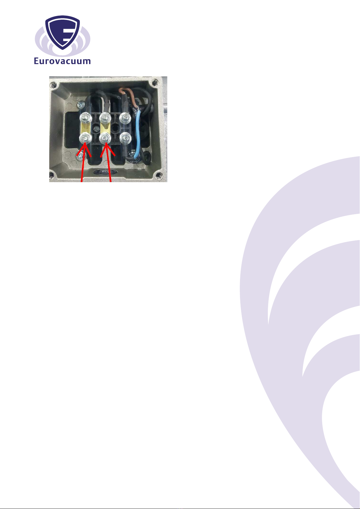
Wiring Scheme- Single Phase Motor
The motor must be connected according to the electrical codes through a fused switch in order to
protect the motor against electrical or mechanical overload conditions. The overload of the motor
starter must be set at a level equal to the full load motor current listed on the motor nameplate.
f the pump is supplied with a motor starter it is preset at the factory according to customer
specifications. t is advisable to check that these settings are in line with the voltage at your location.
f the voltage is different, please contact Eurovacuum for motor and starter information.
Correct direction of rotation is marked by an arrow on the motor fan housing and is counter
clockwise when looking at the motor from the motor's fan side.
After electrical connections have been made, but prior to filling with oil, the rotation of the
motor should be checked. If backward, reverse any two leads of the three phase at the power
connection.
1.3 Vacuum Connections
Use a pipe size that is at least the size of the pump inlet connections. Smaller lines result in a
reduced pump capacity.
Pumps operating in parallel on a common main line should have a manual or automatic operated
shut-off valve or positive action check valve, installed in the suction line adjacent to the pump
suction flange. The built-in anti-suck back valve should not be used as a shut-off valve for the
vacuum system. Remove the protective cap from the inlet port prior to connection of pump to the
system.
Should process gas contain dust or other foreign particles, a suitable in line (inlet) filter should be
connected to the inlet port. Consult Eurovacuum for recommendations.
The vacuum piping should be designed to ensure that no liquids such as condensate or liquid
carried over from the process can reach the pump. f this possibility exists, a knock-out liquid
separator should be installed. Consult Eurovacuum for recommendations.
f an exhaust manifold is connected, install a drip leg and drain near the pump exhaust to prevent
exhaust condensation from entering the exhaust box. The following thread sizes are standard on the
Eurovacuum pumps (NPT thread is available upon request)
Pump Model Inlet Size Exhaust Size
EV-0010/0016/ 0021 ½" G 1¼” G or Open Grid
EV-0030/0040 1¼" G 1¼" G
EV-0063/0100 1¼" G 1¼" G
EV-0160/0215 2" G 2" G
EV-0175/0250/0300 2" G 2" G
EV-0450/0500/0630/0750 3" G 3" G
1.4 Oil illing
The pump is shipped without oil. After level installation and correct rotation has been established, fill
the pump with recommended vacuum pump oil through the oil fill port. Oil level should be at the 3/4
positions on the oil sight glass.
Non-detergent oil should be used. We recommend original Eurovacuum Vacuum Pump oil.
Eurovacuum oil is a high quality vacuum oil that will provide longer running time between oil
changes, better lubrication at high operating temperatures and prolongs the life of the exhaust filter
elements. Oil detergent additives can cause exhaust filters to become clogged and shorten their
service life.
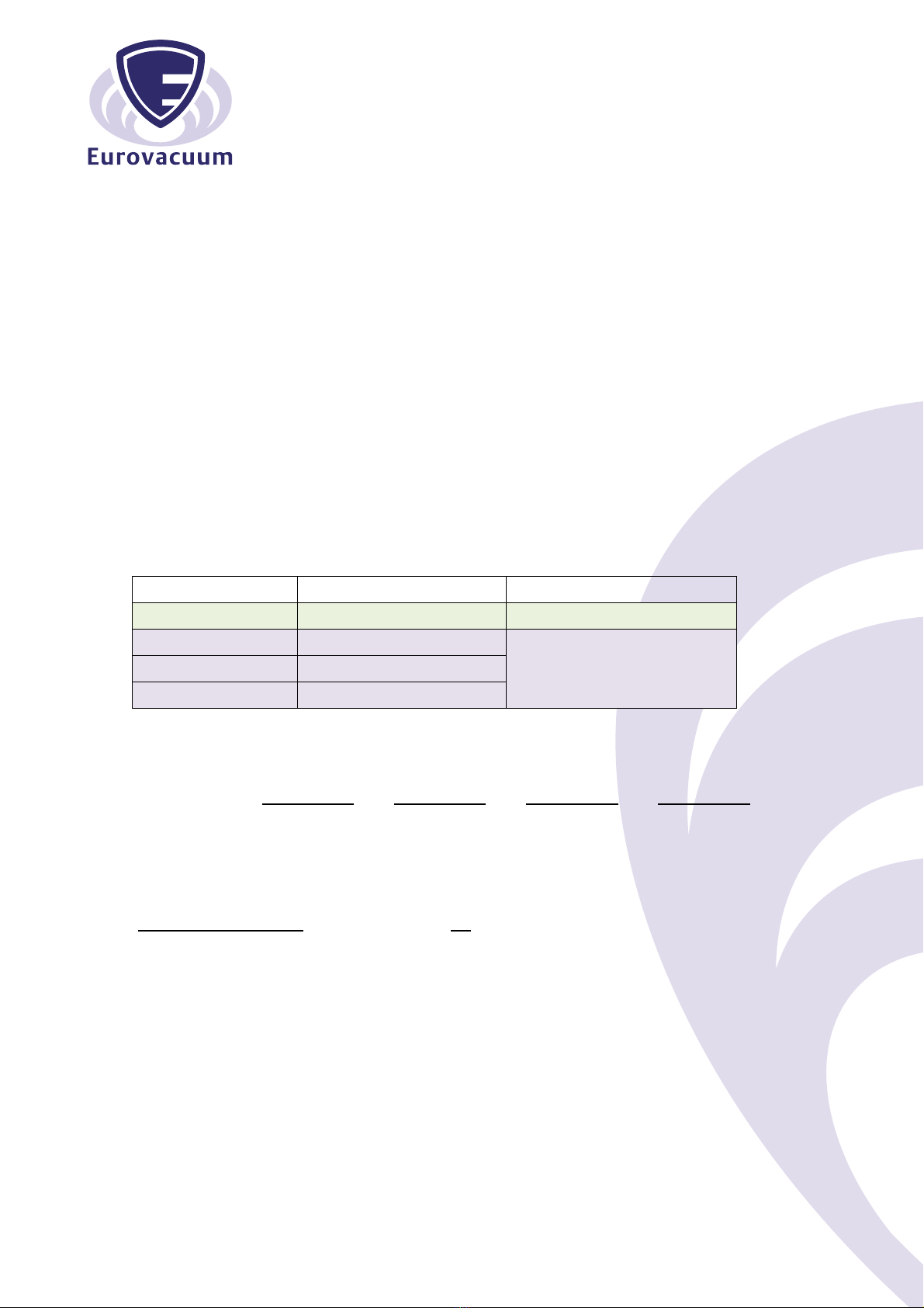
Depending on the ambient temperature around the pump, following oil is recommended.
Ambient Temp. Type of Oil For Model
0ºC~ 30ºC EV-Mineral Oil-32 EV-0010, 0016 & 0021
< 0ºC EV-Mineral Oil-32
EV-0030 till EV-0750 0ºC~ 30ºC EV-Mineral Oil-100
> 30ºC or < 0ºC EV-Syntheti Oil-500
Ordering information on Eurovacuum oil:
Mineral oil Mineral oil Synthetic oil Foodgrade oil
EV-mineral 32 EV-mineral 100 EV-synthetic 500 EV-foodgrade 100
Article number Article number Article number Article number
1 ltr can 100110 100100 100200 100300
5 ltr can 100112 100102 100202 100302
20 ltr can 100113 100103 100203 100303
The following table gives the approximate quantities of oil required for each model.
Pump Model Capacity (ltr)
EV-0010/0016/0021 0,5
EV-0030/0040 1,4
EV-0063 2,5
EV-0100 2,7
EV-0160/0215 7,0
EV-0175/0250/0300 7,0+
EV-0450/0500/0630/0750 19,0
Do not add oil with pump running or through the inlet or exhaust ports! Do not overfill.
2.0 SA ETY
Please read the following safety notice carefully before operating the pump.
2.1 General Notices
- Understand fully this installation and operating manual before operation.
- The other person except authorized operator should not operate the pump
- When the pump is not properly working, it should be stopped immediately.
- Eurovacuum shall have no liability for any accident and failure arising from no compliance with
instructions in this manual.
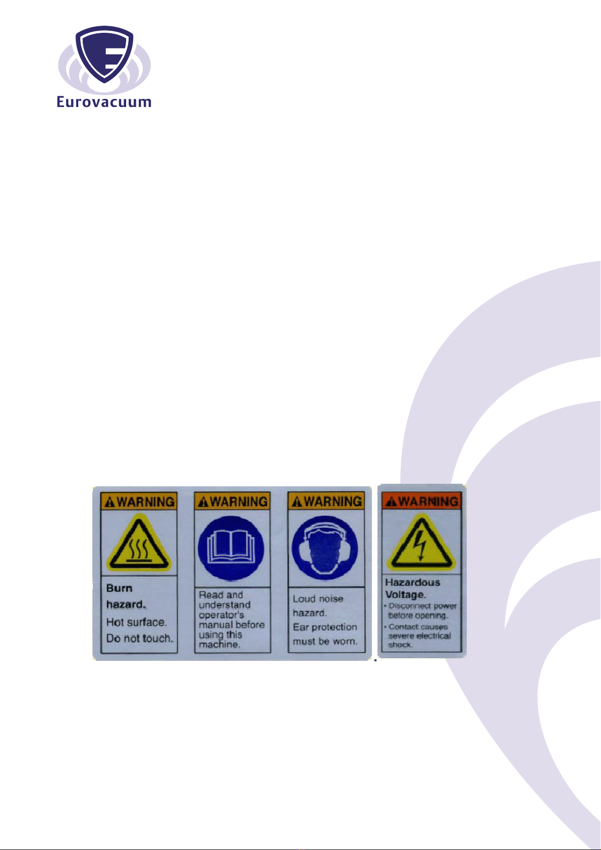
2.2 Warning labels and its explanation
Following warning labels are shown and attached on EV-series pumps
2.2.1 Read and Understand a manual:
Read and understand operator’s manual before using this machine
2.2.2 Burn Hazard:
Hot surface. Do not touch.
2.2.3 Loud noise Hazard:
Loud noise hazard. Ear protection must be worn.
2.2.4 Hazardous Voltage:
Disconnect power before opening. Contact causes severe electrical shock
2.3 Location of the labels
The labels of 2.2.1 Read and Understand a manual, 2.2.2 Burn Hazard and 2.2.3 Loud noise
Hazard shall be shown on the oil sump top of EV-series pump.
The label of 2.2.4 Hazardous Voltage shall be shown on the cover of motor’s terminal box

3.0 OPERATION
3.1 Start-up
Check rotation of the motor as described in paragraph 1.3 Power Requirements.
Fill the pump with oil as described in paragraph 1.5 - Oil Filling
Start the pump with the inlet closed. Run the pump for a few minutes and then shut down. Check the
oil level again and make sure the oil level is between the 3/4 marks and full on the upper oil sight
glass.
Add oil, if necessary. Pump oil should only be added when the pump is off and circulating oil has
sufficient time to return to the oil sump.
f the ambient temperature is below 10°C, it is recommended to use a heater with thermostatic
control to warm up oil to room temperature. f necessary, the heater with control can be used to
keep the oil temperature at operating temperature for immediate start up with system where water
vapor comes in. Please consult Eurovacuum or representative for installation of a heater with
control.
3.2 Stopping the pump
To stop the pump, turn off the power. A built in anti-suck back valve will prevent oil from the oil
reservoir being sucked back into the cylinder after the pump is shutdown.
Do not utilize the anti-suck back valve as a check valve. Consult Eurovacuum for proper
check valves.
3.3 Gas Ballast
Most EV-series pumps are equipped with gas ballast. The gas ballast valve is located between the
inlet port and the exhaust box. ts main function is to prevent water vapour from condensing in the
pump that causes emulsification of the oil resulting in possible pump failure.
n applications, when the quantity of water vapour is moderate, it is recommended to run the pump
for 10 to 30 minutes to its normal operating temperature (about 75˚C), prior to going on process with
suction line shut off. The pump should also be operated off process for 10 to 30 minutes prior to shut
down. A slight air bleed (purge) is recommended during these 10 to 30 minute cycles to prevent the
vapour from condensing in the pump.
3.4 Check Valve (Built-In)
EV-series pumps are equipped with Built-in Check Valve. The valve is located in the inlet flange
housing, which is in the upper part of Pump module to prevent oil back to inlet side (system) when
the pump is running off.
(However, it is recommended to install separate check valve in the line of inlet if necessary)
3.5 Exhaust Pressure Gauge
This gage shall be installed on the Oil fill Plug for easy checking of status of saturation of the
exhaust filter.
f the reading is 0,6 Bar or higher, you need to change the exhaust filter(s) with new one(s).

4.0 MAINTENANCE
EV-Series vacuum pumps require very little maintenance. To ensure optimum performance, the
following maintenance steps should be followed:
4.1 Pump Oil
4.1.1 Oil Level
Under normal circumstances it should not be necessary to add oil between oil changes. A
significant drop in oil level means there is either an oil leak, a defective exhaust filter or O-ring, or
a leaking anti-suck back valve. f the pump is smoking excessively, the exhaust filter may be
installed improperly.
t is normal for the oil to be foamy or lightly coloured in an operating pump. This may be normal
aeration of the oil. f the oil appears milky or dark coloured, it is contaminated or burned and must
be changed.
Check the oil level only when the pump is shut off. Replenish oil if it drops below the ¼ mark of the
sight glass.
Caution: Do not add oil while the pump is running, since hot oil can escape from the oil fill port.
4.1.2 Oil Type and Quantity
See section 1.5 - Oil Filling - for details on oil type and quantity
4.1.3 Oil Change
Oil life is dependent on the operating conditions. A clean and dry air stream and operating
temperatures below 100˚C are ideal. When using proper Vacuum Pump Oil, it is recommended to
change the oil every 500-1000 operating hours or after half year. Oil life can be shorter than 500
hours if the pumps are operated under unfavorable operating conditions Oil change frequency is
dependent upon the application and ambient temperature. t is recommended that the customer
monitor the condition of the oil during this period.
Caution: Always change the oil when the pump is off but still at working temperature.
hen disposing of used oil, please observe the relevant environmental regulations.
4.1.4 Oil Spin-On ilter
Replace automotive-type spin on filter at every oil change.
Pump Model Part No.
EV-0030 ~ EV-0100 006010000
EV-0160 ~ EV-0300 050010000
EV-0450 ~ EV-0750 120010000
4.2 Inline (Inlet) ilter
Check inline (inlet) filter on a weekly basis. The filter cartridge should be cleaned or replaced when
dirty. Consult Eurovacuum for replacement element information.
Caution: Depending on the mounting position of the filter, be careful not to allow
accumulated foreign material to fall in the pump suction inlet when removing the filter
cartridge. Horizontal filter installation is recommended to prevent this.

4.3 Exhaust ilter
Replace these filters every 9 to 18 months of operation or as necessary. The service life of these
filters varies depending upon the application and frequency of oil change. t is necessary to change
these filters only when they become clogged. ndications of clogged filters are smoke or oil mist
coming from the exhaust of the pump, higher than normal motor current, and the exhaust pressure
gauge reading 0,6 bar or greater.
Pump Model Part No. No. required
EV-0010 ~ EV-0021 002012000 1 pc
EV-0030F 0060120B0 1 pc
EV-0040F ~ EV-0100F 0060120B0 2 pc
EV-0160F 0430120A0 1 pc
EV-0160G 0430120B0 1 pc
EV-0215F 0430120A0 2 pc
EV-0215G 0430120B0 2 pc
EV-0175F ~ EV-0300F 0500120A0 4 pc
EV-0450F ~ EV-0750F 1200120A0 8 pc
n cases where the vacuum level of the process is causing a large quantity of oil mist exhausting from
the pump, it is possible to mount the 1200120A0 filters inside of the EV-0175, 0250 & 0300 pumps.
Do not clean or re-use these filters. ilters must be disposed of in a proper way as they might
contain toxic substances carried over from the process. Replace O-rings on filter when
changing.
4.4 Gas ballast filter
Replace or clean the filter every as necessary or annually.
Type: 1) EV-0030 to 0100: Gas ballast without valve with paper filter - Replace paper filter
2) EV-0160 to 0750: Gas ballast with valve & sponge filter – Clean/replace the sponge filter
4.5 Maintenance Chart
Daily : visually check oil level and colour.
Weekly : inspect inline (inlet) filter and check oil leaks from the vacuum pump.
Monthly : check the exhaust filter function
( f oil mist at exhaust, replace the exhaust filter with O-ring).
Every 2- 6 month : drain and discard oil from pump while hot. Refill with fresh oil.
Every 9-18 month : replace exhaust filter elements with O-ring and gas ballast filter.
Every 500 ~ 2000 operating hours:
Change the oil and oil filter. n version of float valve with oil return line,
check the float valve’s operating conditions.
For motor - See the motor manufacture's manual for periodic motor maintenance.
The operating life of the pump is greatly enhanced based on the oil quality and condition of
the filters. Periodic maintenance will ensure a reliable operating vacuum pump.
4.6 Gasket Kit, Overhaul Kit and other Parts
A gasket kit contains a full set of gaskets and O-rings
A Overhaul (Maintenance) kit contains a set of gaskets, O-rings, vanes, bearing, bearing sleeves,
shaft seals and taper pins, oil filter and exhaust filter(s).
A Service kit contains motor coupling insert(s), filters, seals for filter exchange & oil exchange.
Other parts are available. Please consult Eurovacuum parts department for information.

5.0 PROBLEM SOLVING
5.1 Problem
Pump does not reach end pressure. This is the lower absolute (best vacuum) when running with the
inlet closed.
5.1.1 Possible Cause
Oil condition is most often the cause of not reaching end vacuum.
Remedy : drain oil from pump and refill with fresh oil. Run pump with fresh oil for 15 minutes
then take new pressure reading.
5.1.2 Possible Cause
nlet screen clogged with debris.
Remedy : clean screen and check inlet filter element.
5.1.3 Possible Cause
Shaft seal leak
Remedy : replace shaft seal from overhaul kit, or call Eurovacuum for exchange program.
5.1.4 Possible Cause
Vane stuck in rotor slot.
Remedy : drain oil with flushing oil. Run pump for 15 minutes and drain. Replace fluid with
fresh oil, exhaust filter, and spin on filter.
- replace vane from overhaul kit or call Eurovacuum for exchange program
5.1.5 Possible Cause
Anti-suck back valve stuck in closed position due to oil contamination.
Remedy : disassemble valve and screen, clean as required. Drain old oil and replace with fresh
oil.
5.1.6 Possible Cause
No oil or low oil level in reservoir.
Remedy : shut down pump, drain balance of oil and refill with fresh oil.
5.1.7 Possible Cause
Vacuum fitting or hose is not leak tight.
Remedy : check hose and pipe connections for leaks.
5.1.8 Possible Cause
Radial clearance between rotor and cylinder are no longer adequate.
Remedy : overhaul pump or call Eurovacuum for exchange program.
5.1.9 Possible Cause
Float Valve does not close well.
Remedy : check the condition of float valve, and adjust the nozzle position or repair it.

5.2 Problem
Pump runs very noisy.
5.2.1 Possible cause
Coupling insert is worn.
Remedy : replace coupling insert in motor/pump coupling.
5.2.2 Possible Cause
Vanes stuck
Remedy : follow flush procedure from 5.1.4 or replace vane or call Eurovacuum for exchange
program.
5.2.3 Possible Cause
Bearing noise
Remedy : replace bearings or call Eurovacuum or exchange program.
5.3 Problem
Pump starts, but labours and draws high amperage.
5.3.1 Possible Cause
Oil is too viscous.
Remedy : drain and change with fresh oil or correct oil with recommended viscosity.
5.3.2 Possible Cause
Exhaust filter is clogged
Remedy : replace exhaust filters, maintain proper oil condition, oil level and use Vacuum pump oil.
- make sure inlet filter is operational preventing particulate carryover.
5.3.3 Possible Cause
Loose connection in motor terminal box wired for wrong voltage.
Remedy : check wiring diagram for proper connections; tighten or replace loose connections.
5.3.4 Possible Cause
Foreign particles in pump. Broken vanes or seized bearings.
Remedy : overhaul pump or call Eurovacuum for exchange program.
5.3.5 Possible Cause
Pump is overfilled with oil or wrong kind of oil is in pump.
Remedy : drain oil; use correct type of Vacuum pump oil.
5.3.6 Possible Cause
Pump runs in wrong direction.
Remedy : check for correct rotation. f incorrect, switch any two leads.

5.4 Problem
Pump will not start.
5.4.1 Possible Cause
Supply voltage is not proper or is overloaded. Motor starter overload settings are too low or
improper; fuses are burned; wire size is too small or too long causing a voltage drop.
Remedy : check voltage supply; overload settings in motor starter for size and settings
according to motor nameplate. nstall proper size wire. f ambient temperature is high,
use the next larger size overloads or adjust settings 5% above motor nameplate valve.
Remedy : turn pump fan by hand. f it will not turn, remove motor from pump and check motor
and pump separately. Repair or replace if needed or call Eurovacuum for exchange
program.
5.4.2 Possible Cause
Oil temperature is below 12°C or oil is too viscous due to contamination.
Remedy : Heat the pump and oil, or change the oil.
5.5 Problem
Pump smokes at the exhaust side or expels oil droplets from the exhaust.
5.5.1 Possible Cause
Exhaust filters are not properly installed with O-ring; Filter media is damaged.
Remedy : check exhaust filter placement and replace if needed.
5.5.2 Possible Cause
Exhaust filters are clogged with foreign particles.
Remedy : replace filter and O-ring.
5.5.3 Possible Cause
Oil is not re-circulating properly.
Remedy : check oil quality and make certain oil lines are clean.
5.6 Problem
Pump is running too hot. (Typical operating temperature of the EV-Series pump is 50°C ~ 95°C)
5.6.1 Possible Cause
Not enough oil in the oil reservoir or oil is badly burned or carbonized.
Remedy : check upper part of oil sump (open the exhaust filter cover) if there is the oil filled and
not re-circulated to the inlet side of pump, check the condition of float valve (in Oil Sump or Float
Valve Box), and adjust the nozzle position or change the float if float is not float well, or check oil
return line if it is not clogged or not.
Remedy : drain oil and refill with proper Eurovacuum oil; change oil more frequently.
5.6.2 Possible Cause
Not enough air ventilation to the pump
Remedy : clean radiator and motor fins. Make certain a sufficient amount of fresh air is
supplied to the pump.

5.7 Problem
Pump will not operate (seized up).
5.7.1 Possible cause
Pump operated without oil and vanes broke
Remedy : Call Eurovacuum for exchange program
5.7.2 Possible Cause
Liquid carry over into pump cylinder broke vanes while pump was running.
Remedy : nstall knock-out pot at inlet of pump
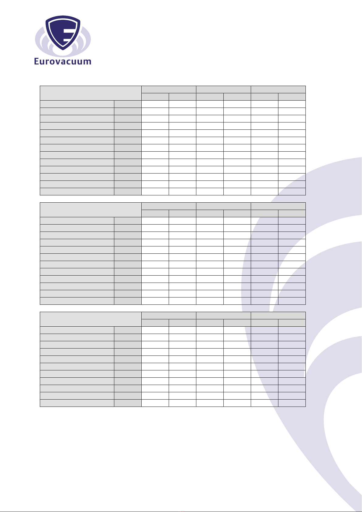
6.0 TECHNICAL DATA
Technical Data EV-0010 EV-0016 EV-0021
50 Hz 60 Hz 50 Hz 60 Hz 50 Hz 60 Hz
Nominal displacement
m
3
/h
10
12
16
19
20
24
Ultimate pressure NM type
mbar
2
2
2
2
2
2
L type
mbar
20
20
20
20
20
20
Motor power
phase
kW
0,4
0,4
0,
55
0,
7
5
0,
75
0,9
Motor power
1
phase
kW
0,4
0,4
0,
7
5
0,
7
5
0,9
0,9
Nominal speed
rpm
1450
1740
1450
1740
2870
480
Noise leve
l
dB(A)
57
59
58
60
60
62
Operating temperature
°C
77
77
80
80
85
85
Oil capacity
ltr
0,5
0,5
0,5
0,5
0,5
0,5
Weight
kg
2
0
20
22
22
20
20
Admissible ambient temp.
°C
10 to 40
10 to 40
10 to 40
10 to 40
10 to 40
10 to 40
Connection Inlet
G(BS
P)
½”
½”
½”
½”
½”
½”
Outlet
G(BSP)
½”
½”
½”
½”
½”
½”
Technical Data EV-0030F EV-0040F EV-0063F
50 Hz 60 Hz 50 Hz 60 Hz 50 Hz 60 Hz
Nominal displacement
m
3
/h
0
6
4
0
48
6
7
5
Ultimate pressure
mbar
0,
1
0,
1
0,
1
0,
1
0,
1
0,
1
Motor power
phase
kW
0,9
1,1
1,1
1,5
1,5
2,2
Motor power
1
phase
kW
1,5
1,5
1,5
1,5
-
-
Nominal speed
rpm
1450
1740
1450
1740
1450
1740
Noise level
dB(A)
64
67
64
67
65
68
Opera
ting temperature
°C
76
76
78
78
85
85
Oil capacity
ltr
1,
4
1,
4
1,
4
1,
4
2,
5
2,
5
Weight
kg
47
47
5
5
6
4
6
4
Admissible amb
ient temp.
°C
10 to 40
10 to 40
10 to 40
10 to 40
10 to 40
10 to 40
Connection Inlet
G(BSP)
1¼”
1¼”
1¼”
1¼”
1¼”
1¼”
Outlet
G(BSP)
1¼”
1¼”
1¼”
1¼”
1¼”
1¼”
Technical Data EV-0100F EV-0160G EV-0175F
50 Hz 60 Hz 50 Hz 60 Hz 50 Hz 60 Hz
Nominal displacement
m
3
/h
100
120
160
1
92
175
210
Ultimate pressure N type
mbar
0,
1
0,
1
0,
1
0,
1
0,
1
0,
1
Motor power
phase
k
W
2,2
,0
,7
,7
5,5
5,5
Nominal speed
rpm
1450
1740
1450
1740
1450
1740
Noise level
dB(A)
65
68
7
2
7
5
74
77
Operating temperatu
re
°C
85
85
85
85
85
85
Oil capacity
ltr
2,
7
2,
7
7
,0
7,0
7,0
7,0
Weight
kg
75
75
124
124
164
164
Admissible ambient temp
.
°C
10 to 40
10 to 40
10 to 40
10 to 40
10 to 40
10 to 40
Connection Inlet
G(BSP)
1¼”
1¼”
2”
2”
2”
2”
Outlet
G(BSP)
1¼”
1¼”
2
”
2
”
2”
2”
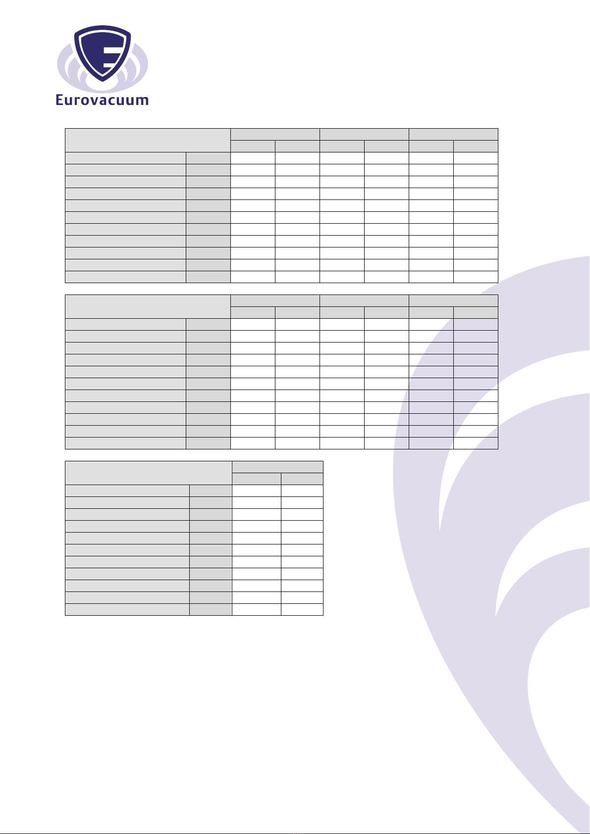
Technical Data EV-0215G EV-0250F EV-0300F
50 Hz 60 Hz 50 Hz 60 Hz 50 Hz 60 Hz
Nominal displacement
m
3
/h
215
258
250
00
00
60
Ultimate pressure
mbar
0,
1
0,
1
0,
1
0,
1
0,
1
0,
1
Motor powe
r
kW
5,5
5,5
5
,5
7,5
7,5
9,2
Nominal speed
rpm
1450
1740
1450
1740
1450
1740
Noise level
dB(A)
74
77
74
77
75
78
Operating temper
ature
°C
85
85
85
85
85
85
Oil capacity
ltr
7
,0
7
,0
7,0
7,0
7,0
7,0
Weight
kg
145
145
184
184
188
188
Admissible ambient
temp.
°C
10 to 40
10 to 40
10 to 40
10 to 40
10 to 40
10 to 40
Connection Inlet
G(BSP)
2”
2”
2”
2”
2”
2”
Outlet
G(BSP)
2
”
2
”
2”
2”
2”
2”
Technical Data EV-0450F EV-0500F EV-0630F
50 Hz 60 Hz 50 Hz 60 Hz 50 Hz 60 Hz
Nominal displ
acement
m
3
/h
42
0
505
50
0
6
0
0
6
60
780
Ultimate pressure
mbar
0,
1
0,
1
0,
1
0,
1
0,
1
0,
1
Motor power
kW
11,25
15,0
1
1,25
15,0
15,0
18,5
Nominal speed
rpm
980
1160
980
1160
980
1160
N
oise level
dB(A)
7
6
7
8
77
7
9
77
79
Operating temperature
°C
80
80
8
2
8
2
80
80
Oil capacity
ltr
19
19
19
19
19
19
Weight
kg
491
5
04
5
1
5
44
582
70
Admissible ambient temp.
°C
10 to 40
10 to 40
10 to 40
10 to 40
10 to 40
10 to 40
Connection Inlet
G(BSP)
”
”
”
”
”
”
Outlet
G(BSP)
”
”
”
”
”
”
Technical Data EV-0750F
50 Hz 60 Hz
Nominal displ
acement
m
3
/h
75
0
-
Ultimate pressure
mbar
0,
1
-
Motor power
kW
1
8,5
-
Nominal speed
rpm
1500
-
N
oise level
dB(A)
7
9
-
Operating temperature
°C
8
5
-
Oil capacity
ltr
19
-
Weight
kg
5
5
-
Admissible ambient temp.
°C
10 to 40
-
Connection Inlet
G(BSP)
”
-
Outlet
G(BSP)
”
-

Eurovacuum Head office Tel. +31-(0)854890993
Einsteinstraat 58 [email protected]
2811EP Reeuwijk http://www.eurovacuum.eu
The Netherlands
This manual suits for next models
16
Table of contents
Other Eurovacuum Water Pump manuals


 operating instructions")